working of efsbthe braking torque in excel spring loaded fail safe brake is generated by several compression springs (6) whose axial spring force presses the armature plate (5)against the rotor (3)which in turn is pushed against the mounting flange(2). On applying direct current power supply to the coil (9) magnetic field is produced, which pulls the armature plate over the airgap towards the "stator" against the spring force and the rotor is free to rotate and hence brake is released.
the brakes are provided with manual hand release assembly and can be used for releasing the brake in case of power failure.
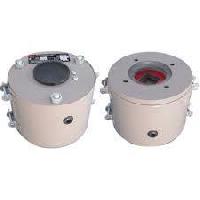
description
- 1. Dust protective ring
- 2. Flange
- 3. Rotor
- 4. Tubular bush
- 5. Armature plate
- 6. Compression spring
- 7. Compression parts
- 8. Hub
- 9. Outer pole
- 10. A- handle
- b- h.r. Lever
- c- knob
- d- h.r. Spring
- e- h.r. Bolt
- 11. A- spring washer
- 12. Torque adjustment nutsize selection and ordering information approximate necessary torque or size of a unit for applications involving low inertia & low operating frequency is determined as ; torque = [ 9550 x (k.w. / speed)] x safety factor [k]
safety factor [k]to ensure necessary transmission safety also under extreme operating conditions adequate safety factor must be considered the value of which depends on operating conditions namely, the type of load, prime mover etc. Typically [k]for electric drive
- low masses equal loading & non-intermittent operation [2.0]
- low masses light shock load & intermittent operation [2.5]
- medium masses, light shock load & intermittent operation [3.0]
- large masses, light shock load & intermittent operation [3.0]
- non-overhauling loads [2-3]
- overhauling loads [3-4]
- diesel engine drive [4-5]
- compressor driven [5-6]
however, we recommend you to perform detailed calculations for which please consult us.
life of friction materialthe life of the friction liner depends on a number of factors namely, the inertia to be retarded or stopped, the relative speed, the operating frequency, the temperatures at the friction surfaces etc. These brakes must run dry. Oil, grease, foreign materials & other lubricants affect life and characteristics of friction material.
electrical connectionsthe brakes are operated with dc. Connection from three phase or ac mains network can be made via a transformer rectifier, bridge rectifier or half wave rectifier. To restrict the high inductive voltage / back emf a suitable supressor and capacitor network is provided across the connector coil as shown in fig.