Our Products

AlE Offers Auto Instruments & Engineers make Electronic Extensometer AIE-EE2 to measure material extension with a Resolution of 1- Micron. Strain Gauge type Extensometer is to be used up to Elastic Limit to Determine Important Parameters Like 0.1 %, 0.2% Proof Stress & Young's Modulus, proof stress from 0.1 % to 1 % Selectable.
Specifications :
Gauge length 25 mm to 50 mm
Maximum extension 2 mm
Resolution 1 micron
Specimen dia 0.5 to 30mm
Specimen thickness up to 30 mm
Specimen width up to 30 mm
Description :
Serial port (RS-l31) communication is available with Windows based operating software
Wide range of data entry for easy test setup
Unit interchangeability for input and results as per standard.
Extensive graphics, curve / tracing
Results printing formats
Output parameters include U. T. S. young's modulus, % elongation, yield stress, proff stress selectable from O. 1 % to 1 % (when extensometer is used)
Online graph facility
Time graph also available.
Batch testing facility.
Prodf stress lines can be seen on monitor.
Reductions in area.

Features :
Loading accuracy as high as 1 %
Straining rate to cover a wide range of materials.
Motorised loading and unloading.
High reading accuracy due to large size and design diel.
Simple control to facilitate ease of operation.
Fully enclosed and protected load measuring system.
Wide range of standard and special accessories including load stabilizer.
Robust straining frame.
High reading accuracy due to large size and design diel.
Motorised UP/DOWN movement of lower crosshead to enable easy and rapid fixing of test specimen.
Application :
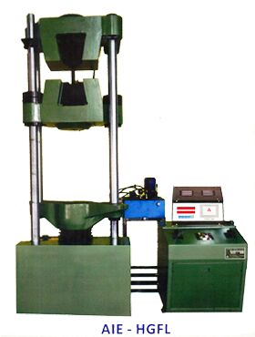
Universal Testing Machine is designed to perform Tensile, Compression, Bending and shear tests on metal & Other materials both in the form of test pieces and as finished products.
Principle of operation :
The test specimen is subjected to load with hydraulic system and is measured precisely with pendulum dynamometer.
Load is applied by a hydrostatically lubricated ram.The oil pressure in the main cylinder is transmitted to the cylinder of the pendulum dynamometer housed in the control panel, the dynamometer piston exerts a force proportionate to the hydraulic pessure.This force is transferred through a leverage system to a pendulum. Displacement of pendulum actuates the rack and pinion mechanism which operates the load indicating pointer. Return movement of pendulum is effec- tively damped to absorb energy in the event of sudden breakage of specimen.
Machine comprises ofthe following:
Strainung Unit :
This consists of a hydraulic cylinder & piston mounted on a robust base. The loading frame consists of an upper crosshead, middle crosshead and lower table. The upper crosshead and lower table is connected by means of two plain hard chrome plated columns. The middle cross head is fitted on two hard chrome plated threaded columns. A reduction gear motor drives the chain and sprockets fixed at the bottom of the threaded columns for height adjust- men!.
The cylinder and ram is individually lapped to eliminate friction.Axial loading of the system is ensured by provision of a ball seating under the lowertable.
An elongation scale with least count of 1 mm is provided for measurement of deformation on various samples.
Tensile test is conducted by gripping the test specimen between the upper and middle crosshead.Compression, Transverse, Bending and Shear tests are conducted between the Shear tests are conducted between the middle crosshead and the lower table.
Control Panel :
The control panel consists of the hydraulic system .complete with drive motor, oil sump, pendulum dynamometer and the load indicating system.
Hydraulic System :
The power pack has a directly driven pump which generates a maximum pressure of 200 kgf/cm2. he hydraulic pump producs a continuous non- pulsating oil flow. Hence the load application is very smooth. Oil filter, oil stranier, air breather, oil level indicator and drain plug is provided in the power pack. A pressure compensated flow to the main cylinder. This maintains constant rate of piston movement andhence straining rate is kept constant. This valve is hand operated and gives infinitely variable oil flow to obtain different rates of straining.
Pendulum Dynamometer :
The oil pressure in the main cylinder actuates the special dynamometer system. Pressurised oil in the loading cylinder pushes up the measuring piston proportionately and deflects the pendulum. The piston is constantly rotated to eliminate friction. The system has effective damping arrangement to ensure smooth return of pendulum aftersudden breakage of test piece. This unit permits selection of favourable hydraulic ratios producing relatively small frictional forces.
Load Indicating System :
This system consists of a large dial and a pointer. Displacement of pendulum actuates the rack and pinion mechanism, which operates the load indicating .pointer. The pointer moves over a large dial indicating the load. A dummy pointer is provided toregister the maximum load reached during the test. Window type dial is provided for easy and clear changing of load range.
Load / Elongation Recording System :
A continuous roll ( A strip chart) type load-elongation recorder is provided for plotting load-elongation graph. Horizontal movement of the rack produces load ordinate of the diagram and drum rotation to elonga-tion ordinate, in the ratio of either 1:5 or 1:10.
Electronic Universal Testing Machine :
Construction : AImake electronic Universal Testing machines comprise of
a) Loading Unit
b) Measuring Control Panel
a) Loading Unit :This is similar to standard loading unit of analogue type universal testing machin. In addition to standard features of regular loading unit, a ROTARY ENCODER is attached to the hydraulic ram to get accurate displacement of the ram.
b) Measuring Control Panel :This includes,
| Model | Units | UTE-10 | UTE-20 | UTE-40 | UTE-60 | UTE-100 | UTE-200 | UTE-300 |
|---|---|---|---|---|---|---|---|---|
| Maximum Capacity | VK | 100 | 200 | 400 | 600 | 1000 | 2000 | 3000 |
| Measuring Range | kN | 0-100 | 0-200 | 0-400 | 0-600 | 0-1000 | 0-2000 | 0-3000 |
| Load Revolution (20,000 counts full scale) | N | 5 | 10 | 20 | 30 | 50 | 100 | 150 |
| Load Range with Accuracy of measurement +1.0% | kN | 2 to 100 | 4 to 200 | 8 to 400 | 12 to 600 | 20 to 1000 | 40 to 2000 | 60 to 3000 |
| Resolution of piston movement (Displacement) | mm | 0.1 | 0.1 | 0.1 | 0.1 | 0.1 | 0.1 | 0.1 |
| Clearance for tensile at fully descended working piston | mm | 50-700 | 50-700 | 50-700 | 50-800 | 50-850 | 50-900 | 50-900 |
| Clearanc for cbmpression test at fully descended working piston | mm | 0-700 | 0-700 | 0-700 | 0-800 | 0-850 | 0-900 | 0-900 |
| Clearanc between columns. | mm | 500 | 500 | 500 | 600 | 750 | 850 | 850 |
| Ram Stroke | mm | 150 | 200 | 200 | 250 | 250 | 300 | 300 |
| Straining/piston speed (at no load) | mm / mm | 0-300 | 0-150 | 0-150 | 0-100 | 0-80 | 0-45 | 0-50 |
| CONNECTED LOAD | ||||||||
| Power | kW | 1.0 | 1.0 | 1.7 | 1.9 | 2.6 | 4.9 | 6.4 |
| V | 400-440 | 400-440 | 400-440 | 400-440 | 400-440 | 400-440 | 400-440 | |
| Ø | 3 | 3 | 3 | 3 | 3 | 3 | ||
| DIMENSIONS | ||||||||
| LxWxH (approx.) | mm | 2032 X 750 X 1960 | 2032 X 750 X 1960 | 2060 X 750 X 2180 | 2265 X 750 X 2534 | 2415 X 815 X 2900 | 3000 X 1200X 3600 | 3500 X 1900 X 4550 |
| WEIGHT (approx.) | kg. | 1500 | 1500 | 2500 | 3500 | 5500 | 9500 | 15,000 |
| STANDARD ACCESSORIES | ||||||||
| FOR TENSION TEST | ||||||||
| Clamping jaws for round specimens of Diameters. | mm |
10-20 20-30 |
10-20 20-30 |
10-25 25-40 |
10-25 25-40 40-55 |
10-25 25-45 45-70 |
10-40 40-60 60-80 |
25-50 50-70 70-90 |
| Clamping jaws for flat specimens of thickness. | mm |
0-10 10-20 |
0-10 10-20 |
0-15 15-30 |
0-15 15-30 |
0-22 22-44 44-65 |
0-20 20-45 45-70 |
0-25 25-50 50-75 |
| width | mm | 50 | 50 | 65 | 70 | 70 | 90 | 100 |
| FOR COMPRESSION TEST | ||||||||
| Pair of compression plates of dia. | mm | 120 | 120 | 120 | 120 | 160 | 220 | 220 |
| FOR TRANSVERSE TEST | ||||||||
| Table with adjustable rollers width of rollers. | mm | 160 | 160 | 160 | 160 | 160 | 200 | 200 |
| Diameter of rollers | mm | 30 | 30 | 30 | 50 | 50 | 70 | 70 |
| Maximum clearance between supports | mm | 500 | 500 | 500 | 600 | 800 | 900 | 1000 |
| Radius of punch tops | mm | 6.12 | 6.12 | 12.16 | 16.22 | 16.22 | 30.40 | 50.75 |


Features
Simultaneous indication of unbalance g/oz
D.C. braking at end of cycle.
Data feeding through numeric keys.
Facility for static balancing and fine mode.
Quick lock nut for faster action.
Horizontal spindle simulates actual case.
Self calibration programme.
Optimisation Programme.
Error code indication.
Programme for Alluminium alloys Rims.