Listing ID #964163
Company Information
Ask for more detail from the seller
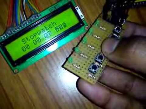
Contact SupplierMicrocontroller Based Digital Stop Watch is a microcontroller based project. As the name suggests, the project is used to measure the time taken by any given activity. It can be used to measure the time required by a runner to complete a race, for example. The circuit starts counting from 00:00 seconds and counts up to 99.99 seconds. There are three buttons on the board: 1) Start =To start the Stopwatch. On pressing this button the watch starts counting from 00:00 seconds 2) Stop=This button stops the watch and the display freezes to show the number of seconds elapsed since pressing the Start button. To continue counting further Start may be pressed again. 3) Reset=This button works when clock is stopped. It is used to reset the clock to 00:00. The time is displayed on 4 seven segment displays in the format 00:00 seconds.
About the circuit :
The circuit has the microcontroller AT89C51 at its heart. Initially when VCC supply is provided to the circuit, the stopwatch goes in Reset mode with 00:00 displayed on the seven segments. The time is displayed on seven segments by using the concept of multiplexing. Multiplexing means displaying a digit on a seven segment display for a fraction of a second and then proceeding to display next digit on next seven segment, displaying on only one seven segment at any instant. Due to fast switching of the displays the data appears constant to our eyes as the human eye is not capable of seeing such speedily. The seven segments are connected to Port P2 (pins 21 to 28) of microcontroller through its data pins (a to h). The enable pins of seven segments (common anodes) are connected to Port P1 (pins 1 to 4) of the microcontroller through transistors BC547. The transistors do the job of switching the displays. It has three pins: 1-Emitter, 2-Base and 3-collector. The base pins of BC547 (pin 2) are connected to the port pins 1 to 4. While the collector (pin no.3) is connected to +5v and emitter (pin no.1) is connected to the Common Anode of 7 segments. So when a high is given on port pin, the transistor allows the current to flow across emitter and collector thus giving +5v to Common Anode. As a result the display is enabled and it begins to glow for the amount of time the port pin is high and shows the data output on Port P2. Pin no. 18 and 19 are connected to the crystal. The function of crystal is to give pulses to the microcontroller which allows the microcontroller to do various calculations. Pin no. 9 of the microcontroller is connected to +5v through a capacitor of 10uF/50v. This causes the microcontroller to reset at Power ON and to begin execution of program from the first line. Pin 5,6 and 7(Port P1) are connected to switches S1, S2 and S3 while the other end of switches are connected to Ground. So when a button is pressed the port P1 pin 5, 6 and 7 get a low depending on which button is pressed and the software inside the microcontroller can take appropriate action. IC 7805 is a voltage regulator IC. It is connected in the input voltage line and limits the voltage to +5v to the circuit. Even if the input voltage goes high up to 14 volts, this IC gives only +5v to the circuit thus preventing any damage. It is a microcontroller based (89C51) system, which operates using seven segment displays and counts up to 99.99 seconds.


Connect with us