Our Product / Services

Bimetallic Traps are the example of thermostatic designs. Bimetallic Traps features one or more strips or discs made up of two different metals with dissimilar thermal-expansion rates. Bimetallic Traps are only minimally affected by back pressure. They excel in projects requiring high energy use or temperature control.

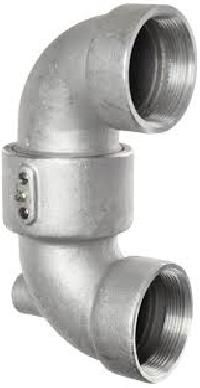
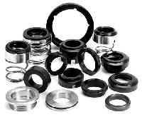
Rex H-series rotary joint is a self supported unit designed specifically to run at higher machine speed and higher pressure and temperature than conventional self-supported joints with a minimum of downtime. The carbon or carbon filled PTFE seal under compression rather than tensile load provides higher strength and exceptional service life. Two wide spaced carbon bush bearings ensure absolute support. With two separate bush bearings, a greater contact area is maintained between the bushes and nipple. This means the H-Series joint has much greater radial support than single guide ring joints a difference that translates longer. These carbon guide bushes are locked into place with the joint housing by pins or keys. They are available in a full range of sizes from ½” to 10” in through flow, dual-flow with stationary syphon and dual-flow for rotating syphon services. Rex H-Series joints can be used with practically all media. They are particularly recommended for higher temperature up to 350 Degree Centrigrade. Hot Oil application or where severe thermal expansion is present. They are suitable for 510 PSI (35 Bar ) pressure and 6500F (350 Degree Centrigrade) temperature and maximum speed up to 200 rpm.
THE BENEFITS

An improved method of connecting Rex Rotary Joint is provided in the Quick Release Nipple. It eliminates threaded nipple and makes removal of the Joint very easy. It reduces inventory requirements too since it eliminates need for RH and LH threaded nipples.
THE BENEFITS

Rex C-Series is a self-supporting version of the Rex Joints, which requires, no external supports of any kind. They are the best known, most widely used in Paper, Textile, Plastics, Rubber, Chemical, Food and many other industries. They are available for through-flow service and stationary siphon pipe applications. Standard series joints are suitable for pressure up to150 PSI. The C-Series Rex Joints are regularly furnished with cast iron housing and end cover. The carbon or carbon filled PTFE seal ring under compression rather than tensile load provides higher strength and exceptional service life. Two wide spaced carbon bush bearing ensure absolute support and substantially reduced wear. The carbon bush bearings are made of specially formulated carbon graphite and seal rings are made of carbon filled P.T.F.E. which require no lubrication of any sort. The spring is made of the finest spring steel stainless steel wire for better resistant to rust, corrosion and erosion. They are available in sizes from ½” to 4”.
THE BENEFITS

Rex N-Series is a rod-supported version of the Rex joints. The N-Series in a specialized variation, designed for use where an internal inlet or outlet pipe must rotate with the roll on paper machine dryers with rotary siphons, double shell dryers, rotary steam tube dryer and similar machines. The N-Series Rex Joints accommodate a rotating syphon or distribution pipe as an integral part of the rotating assembly. Nipple and thrust collar keyed together, rotate against carbon graphite seal rings. Thrust collar serves as packing box to prevent leakage along inner pipe; however, rotate as a unit and seal between stationary and rotating part does not rely on any packing. Spring is for initial seating only; in operation joint is pressure sealed. They are available in sizes from ½” to 10”. Standard series joints are suitable for pressure up to 150 PSI. Heavier series joints are suitable for pressures up to 250 PSI.
THE BENEFITS

Rex J-Series is a rod-supported version of the Rex Joints. The J-Series joints are available for stationary syphon pipe and through-flow service. Lugs cast on sides of body so that simple rods can be used to support the weight of the joint and connections.
Rotating assembly literally “float” inside the body for longer, trouble free service, since its only task is to maintain an effective seal. Nipple and thrust collar keyed together, rotate against carbon graphite seal rings. Spring is for initial sealing only; in operation joint is pressure sealed. They are available in sizes from ½” to 8”. Standard series joints are suitable for pressure up to 150 PSI. Heavier series joints are suitable for pressure up to 250 PSI.
THE BENEFITS


Steam Traps should be inspected to determine whether they are functioning properly or allowing live steam to blow through. Generate a program for periodic inspection and maintenance of traps. Ensure correct reporting and evaluate monetary savings. Typically, high pressure traps should be inspected at least twice a month, medium pressure traps once in two months, and low pressure traps once in six months. Plants where traps haven't been inspected or maintained for 3 years or more could have up to 30% of their traps blowing steam. This could be brought down to less than 5% with a well designed and executed maintenance program. Why Steam Trap Management System is Necessary?Steam for process heating and turbine drives plays a vital role in today’s chemical process plants. Much attention has been devoted to energy conservation of steam generators (boilers) and process equipments (heat exchangers, dryers, evaporators etc). However a large quantity of energy lost in transporting steam from boilers to different areas of the plant. Large chemical plants like fertilizers, petrochemicals, refineries etc. have kilometers of steam network which could be major energy guzzlers if proper attention is not given to this area. Reducing energy losses in the distribution or transmission system also helps in improving the ‘end-use’ efficiency. The various losses associated with the steam distribution pipes and fittings could add to a significant amount. Worse still, energy losses in this area could rise very sharply, if unchecked, as the plant gets older. The losses could be minimized by continuous monitoring and proper maintenance of steam supply pipelines. Consider that one leaking DN 15 steam trap on a 10 kg/cm² (g) distribution line can lose upto 25 kg of steam per hour. For a plant that operates 365 days a year, 24 hours a day, with a steam cost of Rs. 1.30 per kg, this translates to a loss of Rs.2, 84, 700.00 Extrapolate this to a plant with 300 traps installed with 10% traps leaking and this becomes Rs. 85, 41, 000.00 for the year.
Steps in Steam Trap Management :
Rectify faults found during trap assessment :
Develop a trap database and establish frequent checking :
The major areas of energy conservation in steam lines are the following :Insulation, condensate recovery, Trap flash loss, steam trap leakage, external steam leakage, pressure loss due to improper piping sizing and pipe redundancy. The paper is based in the practical experience of the author in the area of energy auditing of steam networks in large number of industries. It discusses energy conservation aspects of few of the major areas like insulation, steam trap selection, condensate recovery, flash steam recovery in detail. The energy audit methodology of hot-pipe insulation, calculation of heat losses, criteria of and selection of appropriate type and thickness of insulation and is presented in the paper. The use of protective covering along with the common types used in industry is highlighted. In many plants, most of the steam traps are actually steam wasters. Proper selection of steam traps results in a long-lasting, trouble free steam distribution system. Different types of steam traps, their advantages, and disadvantages, evaluation of performance is also discussed. Live steam losses from leakages in steam pipeline are another major area of energy loss in the distribution network. The monetary loss incurred by an industry due to leakage of steam at different pressures is calculated for different aperture sizes and presented in the paper. In most applications, only the latent heat of steam is extracted, and the condensate contains the sensible heat (about 25% of the original heat content). Further the water has been treated to avoid scale formation in boilers, and hence is of very pure. As a result we are a distinguished company providing steam trap management services.
Steam Traps Should Be Inspected to Determine Whether They are Functioning Properly or Allowing Live Steam to Blow Through. Generate a Program for Periodic Inspection and Maintenance of Traps. Ensure Correct Reporting and Evaluate Monetary Savings. Typically, High Pressure Traps Should Be Inspected At Least Twice a Month, Medium Pressure Traps Once in Two Months, and Low Pressure Traps Once in Six Months. Plants Where Traps Haven't Been Inspected or Maintained for 3 Years or More Could have Up to 30% of Their Traps Blowing Steam. this Could Be Brought Down to Less Than 5% with a Well Designed and Executed Maintenance Program. why Steam Trap Management System is Necessary? steam for Process Heating and Turbine Drives Plays a Vital Role in Todays Chemical Process Plants. Much Attention Has Been Devoted to Energy Conservation of Steam Generators (boilers) and Process Equipments (heat Exchangers, Dryers, Evaporators Etc). However a Large Quantity of Energy Lost in Transporting Steam from Boilers to Different Areas of the Plant. Large Chemical Plants like Fertilizers, Petrochemicals, Refineries Etc. have Kilometers of Steam Network Which Could Be Major Energy Guzzlers if Proper Attention is Not Given to this Area. Reducing Energy Losses in the Distribution or Transmission System also Helps in Improving the end-use Efficiency. the Various Losses Associated with the Steam Distribution Pipes and Fittings Could Add to a Significant Amount. Worse Still, Energy Losses in this Area Could Rise Very Sharply, if Unchecked, as the Plant Gets Older. the Losses Could Be Minimized By Continuous Monitoring and Proper Maintenance of Steam Supply Pipelines. consider that One Leaking Dn 15 Steam Trap On a 10 Kgcm (g) Distribution Line Can Lose upto 25 Kg of Steam per Hour. for a Plant that Operates 365 Days a Year, 24 Hours a Day, with a Steam Cost of Rs. 1.30 per Kg, this Translates to a Loss of Rs.2, 84, 700.00 Extrapolate this to a Plant with 300 Traps Installed with 10% Traps Leaking and this Becomes Rs. 85, 41, 000.00 for the Year. steps in Steam Trap Management : train Personnel Locate and Identify (tag) Every Trap Assess the Operating Conditions of Every Trap Trap Operation Trap Selection Trap Installation Condensate Return rectify Faults Found During Trap Assessment : replace Leaking Traps Replace Wrongly Selected Traps Replace Leaking Valves Ensure Effective Condensate Return develop a Trap Database and Establish Frequent Checking : high Pressure Check Monthly Medium Pressure Check Quarterly Low Pressure Check Every Six Months the Major Areas of Energy Conservation in Steam Lines are the Following : insulation, Condensate Recovery, Trap Flash Loss, Steam Trap Leakage, External Steam Leakage, Pressure Loss Due to Improper Piping Sizing and Pipe Redundancy. the Paper is Based in the Practical Experience of the Author in the Area of Energy Auditing of Steam Networks in Large Number of Industries. It Discusses Energy Conservation Aspects of Few of the Major Areas like Insulation, Steam Trap Selection, Condensate Recovery, Flash Steam Recovery in Detail. the Energy Audit Methodology of Hot-pipe Insulation, Calculation of Heat Losses, Criteria of and Selection of Appropriate Type and Thickness of Insulation and is Presented in the Paper. the Use of Protective Covering Along with the Common Types Used in Industry is Highlighted. in Many Plants, Most of the Steam Traps are Actually Steam Wasters. Proper Selection of Steam Traps Results in a Long-lasting, Trouble Free Steam Distribution System. Different Types of Steam Traps, Their Advantages, and Disadvantages, Evaluation of Performance is also Discussed. Live Steam Losses from Leakages in Steam Pipeline are Another Major Area of Energy Loss in the Distribution Network. the Monetary Loss Incurred By An Industry Due to Leakage of Steam At Different Pressures is Calculated for Different Aperture Sizes and Presented in the Paper. in Most Applications, Only the Latent Heat of Steam is Extracted, and the Condensate Contains the Sensible Heat (about 25% of the Original Heat Content). Further the Water Has Been Treated to Avoid Scale Formation in Boilers, and Hence is of Very Pure. as a Result We are a Distinguished Company Providing Steam Trap Management Services.
While money is as good a reason as it gets to save energy, other equally attractive reasons make this effort imperative in the long term. Some of these are related to core issues like global warming, depletion of the earth's resources, pollution, etc., that arise from extensive consumption of fossil fuels and directly affect the lives of all of us. Steam accounts for the major source of industrial energy in many industries. In process heating, more than 60%of thermal energy used is in the form of steam. Because of the ever increasing costs of energy, and because conservation of energy in all forms is imperative, we must seek to understand better and improve the process and energy conservation products by which we generate and use steam. Fuel saving/steam saving opportunities can be significant because companies can identify and implement multiple system improvements, which could collectively yield savings of 10 to 15% in many cases, with a general project payback period of less than 2 years.
Steps in Energy Conservation System :