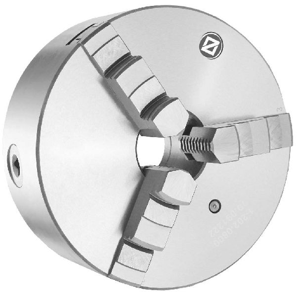
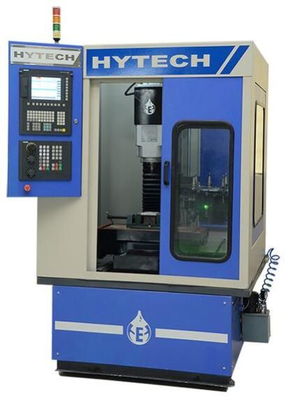
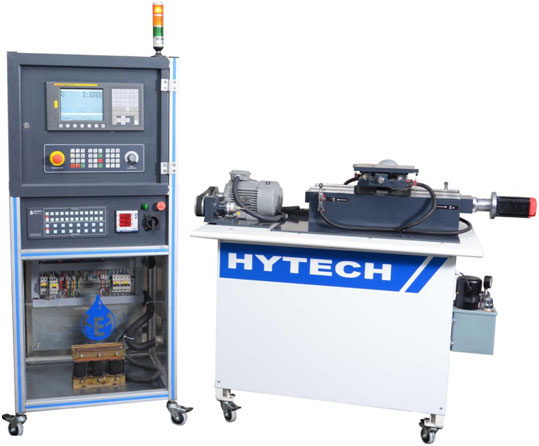
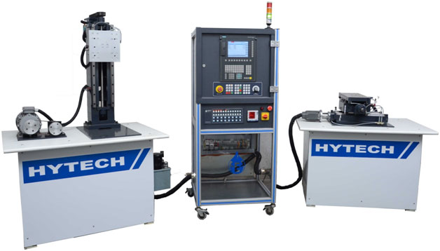
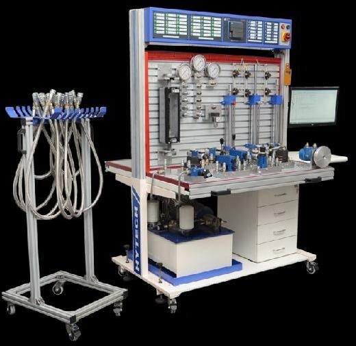
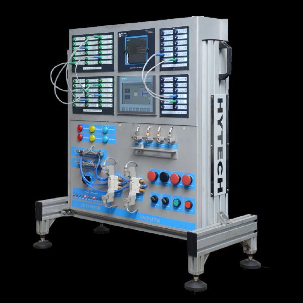
Our Products
Flexible Manufacturing System (FMS)is a system in which Method of producing goods is readily adaptable to the changes in the product being manufactured. A flexible manufacturing system (FMS) gives manufacturing firms an advantage in a quickly changing manufacturing environment.
Hytech Flexible Manufacturing System (FMS)is a prototype of FMS which are currently being used in the industry. It consists of following equipment:
List of Components for Hydraulic Training Kits (Basic and Advance) | |||
Component | Quantity | Make | |
Basic | Advance | ||
Trolley (Aluminum Channel) with frame & caster wheels with Brake (Loadcapacity: 400 Kg) | 1 | 1 | Reputed make |
Hydraulic tank with 30 Litre capacity, Oil cleanliness: Level 8 (With suction filter and return line filter) | 1 | 1 | Repued make |
Variable Frequency Drive for studying pump characteristics | × | 1 | Siemens |
Three Phase flange mounted electric motor 2 HP -1500 rpm | 1 | 1 | Siemens |
Pressure Gauge 0 to 100 Bar. Glycerin filled | 3 | × | Baumer / Burdon make |
Push to read Pressure Gauge Isolator | × | 1 | Repued make |
Gear Pump (Flow Rate: 8 LPM, Max Pressure: 70 Bar) | 1 | × | Dowty / Yuken / Rexroth |
Vane Pump (Flow Rate: 6 LPM, Max Pressure: 140 Bar) | × | 1 | Yuken / Rexroth / Eaton |
Hydraulic Motor Bidirectional . | 1 | 1 | Eaton / Yuken / Danfoss |
Pressure Relief Valve (Direct operated relief valve) | 1 | 2 | Yuken / Rexroth |
Flow Control Valve (Non Pressure Compensated) with Check Valve . | 2 | 2 | Yuken / Rexroth / Eaton |
Flow Control Valve (Pressure Compensated) with Check Valve | 1 | 1 | Yuken / Rexroth / Eaton |
Pressure Sequence Valve | 1 | 1 | Yuken / Rexroth / Eaton |
Pressure Reducing Valve | × | 1 | Yuken / Rexroth / Eaton |
Four way Two position manually operated direction control valve | 1 | 1 | Yuken / Rexroth / Eaton |
Four way Three position manually operated direction control valve – Tandem Center | 1 | 1 | Yuken / Rexroth / Eaton |
Four way Three position manually operated direction control valve – Closed Center | × | 1 | Yuken / Rexroth / Eaton |
Single Acting Cylinder (Stroke: 100mm, Dia: 25mm, Test Pressure: 70 Bar) | 1 | 1 | Rexroth / Eaton / SMC |
Double Acting Cylinder (Stroke: 200 mm minimum Test Pressure 130 Bar) | 1 | 2 | Rexroth / Eaton / SMC |
Check Valve Direct Operated | 1 | 1 | Yuken / Rexroth / Eaton |
Single Pilot Operated Check Valve | × | 1 | Yuken / Rexroth / Eaton |
Needle Valve | × | 1 | Yuken / Rexroth / Eaton |
Pressure Switch | × | 1 | Yuken / Rexroth / Eaton |
Four Way Three Position Double solenoid operated direction control valve | × | 3 | Yuken / Rexroth / Eaton |
Four Way Two Position Single solenoid operated direction control valve | × | 1 | Yuken / Rexroth / Eaton |
Proximity Sensors (Test Voltage 30 V DC max) | × | 8 | Omron / Contrinex |
Electrical control panel with all safety precautions and 230 Volts short circuit protection safety as per DIN standard | × | 1 | Reputed make |
DC Power supply with modulator and rectifier | × | 1 | NHP / Omron |
PLC with 18 Input and 12 Output with Modbus communication and PLC Ladder download facility | × | 1 | Siemens (S7 200 Smart) |
Intel Mother board Computer with 21 inch LED Monitor with Bluetooth keyboard and mouse | × | 1 | Reputed make |
Automgen (IRAI France) – Hydraulic Circuit Simulation Software with Dynamic PLC Ladder updation facility | × | 1 | IRAI France |
Complete trainer kit can be operated directly from software | |||
Automgen (IRAI France) – Hydraulic Circuit Simulation Software | 1 | × | IRAI France |
List of Components for Hydraulic Training Kits (Basic and Advance) | |||
Experiment No | Name of the experiment | Basic | Advance |
1 | Fundamental of pressure and force | YES | YES |
2 | Fundamental of flow rate , velocity , work and power | YES | YES |
3 | Introduction of control valves | YES | YES |
4 | Study of pressure builtup in hydraulic circuit | YES | YES |
5 | Operation of single acting cylinder with 4/2 way DC valve | YES | YES |
6 | Operation of double acting cylinder with 4/2 way DC valve | YES | YES |
7 | Operation of double acting cylinder with 4/3 way DC valve | YES | YES |
8 | Operation of hydraulic motor with 4/2 way DC valve | YES | YES |
9 | Operation of hydraulic motor with 4/3 way DC valve | YES | YES |
10 | Introduction of flow control valve | YES | YES |
11 | Speed control of double acting cylinder | YES | YES |
12 | Speed control of hydraulic motor | YES | YES |
13 | Meter in speed control circuit | YES | YES |
14 | Meter out circuit | YES | YES |
15 | Bleed off circuit | YES | YES |
16 | Introduction of sequence valve | YES | YES |
17 | Introduction of pressure reducing valve | YES | YES |
18 | Two cylinders in series | YES | YES |
19 | Two cylinders in parallel. | YES | YES |
20 | Sequencing of hydraulic cylinder and motor | YES | YES |
21 | Sequencing of two hydraulic cylinders | YES | YES |
22 | Use of pressure reducing valve to vary clamping force | YES | YES |
23 | Introduction of check valve | YES | YES |
24 | Introduction of single pilot check valve | YES | YES |
25 | Cylinder position control by single pilot check valve. | YES | YES |
26 | Introduction of relay and solenoid | NO | YES |
27 | Introduction of sensors, limit switch | NO | YES |
28 | Inch control of double acting cylinder with solenoid valve | NO | YES |
29 | Inching control of hydraulic motor with solenoid valve | NO | YES |
30 | Introduction of PLC and PLC interface | NO | YES |
31 | Operation of single acting cylinder with 4/2 way single sol valve | NO | YES |
32 | Operation of double acting cylinder with single solenoid valve | NO | YES |
33 | Continuous operation of single acting cylinder with 4/2 way single sol valve – AND gate | NO | YES |
34 | Operation of single acting cylinder with single sol valve –OR gate | NO | YES |
35 | Operation of double acting cylinder with single sol. Valve –AND gate | NO | YES |
36 | Operation of double acting cylinder with double sol. Valve –OR gate | NO | YES |
37 | Operation of double acting cylinder with double sol. Valve –AND gate | NO | YES |
38 | Operation of double acting cylinder with double sol valve –NOR gate | NO | YES |
39 | Operation of double acting cylinder with double sol. Valve –NAND gate | NO | YES |
40 | Introduction of up counter | NO | YES |
41 | Introduction of down counter | NO | YES |
42 | Hydraulic motor will stop after 5 rotation | NO | YES |
43 | NAND gate operation with electrical switches double acting cylinder | NO | YES |
44 | Continuous operation of double acting cylinder with double solenoid valve | NO | YES |
45 | Sequencing of cylinders: (A+B+), (A-B-) | NO | YES |
46 | Operation of double acting cylinder with single solenoid valve with on time delay | NO | YES |
47 | Operation of double acting cylinder with double solenoid valve with on time delay | NO | YES |
48 | Continuous operation of double acting cyl. with double sol valve and down counter | NO | YES |
49 | Continuous operation of double acting cylinder with double sol valve and up counter | NO | YES |
50 | Sequencing of two cylinders: cylinder A extends and retracts then cylinder B extends and retract | NO | YES |
MT 250 | SMT 250S_Servo | |
Axes | ||
Axis Motor and Drive | Servo Motor with Servo Drives | Servo Motor with Servo Drives |
X Axis | 300 mm | 300 mm |
Y Axis | 225 mm | 225 mm |
Z Axis | 250 mm | 250 mm |
Ball Screw X / Y / Z | Ø25 x 5 – C4 Class | Ø25 x 5 – C3 Class |
4th Axis Provision (Optional) | Provided | Provided |
Distance between Table top and Spindle Nose | 70 – 370 mm | 70 – 370 mm |
Distance between Spindle to Column | 270 mm | 270 mm |
Feed Rate | 0 to 1,200 mm/min | 0 to 10,000 mm/min |
Rapid Travel | 0 to 1,200 mm/min | 10,000 mm/min |
Table | ||
Table Size | 600 X 160 mm | 600 X 160 mm |
T Slot | 3 x 10 x 50 | 3 x 10 x 50 |
Load On Table | 120 Kg | 120 Kg |
Spindle | ||
Spindle Motor Capacity | 2 HP | 2 HP |
Motor Type | AC Motor with VFD | AC Motor with VFD |
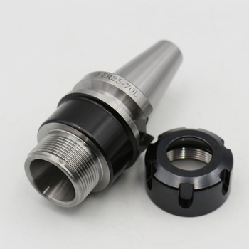
Spindle Nose Taper | ISO 30 / BT 30 | ISO 30 / BT 30 |
Spindle RPM | 100 to 3000 RPM | 100 to 3000 RPM |
CNC Controller Details: | ||
Controller | CutViewer-United Kingdom with Emulation of Fanuc, Siemens , Traub and Heidenhain |
CutViewer-United Kingdom with Emulation of Fanuc, Siemens , Traub and Heidenhain |
Control System | PLC Based Control System | PLC Based Control System |
Operating Software | CutViewer – United Kingdom | CutViewer – United Kingdom |
Keyboard Type | Fanuc Emulated / Standard | Fanuc Emulated / Standard |
Accuracy | ||
Positioning | 0.015 mm | 0.005 mm |
Repeatability | +- 0.010 mm | +/- 0.010 mm |
Resolution | 0.010 mm | 0.001 mm |
4th Axis Resolution (Optional) | 0.02 Degrees | 0.02 Degrees |
Tool Changer (ATC) | ||
Tool Changer | Automatic | Automatic |
No. of Tools | 8 | 8 |
Maximum Tool Length | 40 mm | 40 mm |
Maximum Tool Dia. | 16 mm | 16 mm |
Type of ATC | Umbrella Type | Umbrella Type |
Actuation | Pneumatic / Hydraulic | Pneumatic / Hydraulic |
Machine Details | ||
Run Speed Control | Computer Controlled with Software | Computer Controlled with Software |
Real Time tool path simulation | Provided | Provided |
Vice Type | Pneumatic/ Manual | Pneumatic/ Manual |
Compatible Softwares | MasterCAM, EDGE CAM, Solid Edge, BobCAD | MasterCAM, EDGE CAM, Solid Edge, BobCAD |
Dimension in mm | 1540 x 1200 x 1700 mm | 1540 x 1200 x 1700 mm |
Power Supply | 230V, Single Phase | 415V, +-2% 50 Cycles, 3 Phase |
Controller: Siemens Industrial Controller
Controller Model: 828D
Spindle: Analog with Encoder / Siemens Servo
Mechanical Slides: With Linear Motion Guideways
Automatic Lubrication
CNC Maintenance kits are designed to provide hands on experience to CNC operators or application engineers. Basic function of these kits is to experiment with the electrical panel as well as the ladder diagram of CNC machines.
Participants are trained to solve most of the commonly occurring issues / problems in CNC controllers. It not only involves ladder design but also involves electrical circuit design and understanding. Basic arrangements are provided to distinguish three phase and single phase power supplies. It gives participants necessary confidence and basic understanding of the electrical control panel.
Primary target of the CNC Maintenance Kits is to equip maintenance engineers and CNC operators with necessary skillset to resolve most of the recurring problems in CNC machines.
Mechanical slides are also provided with maintenance kits which allow participants to have hands on experience with hardware related parameters.
Complete operation manual is provided along with each maintenance training kit which is designed in collaboration with OEMs such as Fanuc and Siemens. Operating manual is designed in such a way that it will guide participants to understand the basic operation and maintenance parameters of CNC systems.
Electrical panel is designed with completely isolated circuits for different operating voltages with color coded cables. Check points are provided to check the voltage at different checkpoints with proper safety precautions to avoid any accident.
Few of the experiments that can be carried out on maintenance kits are mentioned below:
Prestigious Customers:
Siemens S7 200 Smart PLC and KTP 700 HMI Trainer Kit | Siemens S7 1200 Smart PLC and KTP 700 HMI Trainer Kit | Siemens S7 300 PLC and KTP 900 HMI Trainer Kit | Siemens S7 1500 PLC and KTP 900 HMI Trainer Kit | ||
Description | Qty for Each Set | Qty for Each Set | Qty for Each Set | Qty for Each Set | Make |
PLC Workstation which is floor mounted and made up of Aluminum profiles. MDF Desk is provided with minumum dimensions of 1200mm x 600mm x 35mm(Thickness) on which four students can work at a time. Four revolving wheels are provided for easy movement.. Computer is mounted on the workstation (Optional). Pedestal with 4 drawers in MDF should be provided with minimum total dimension of (wd-400mm x D-450mm x Ht-550mm) | 1 (Optional) |
1 (Optional) |
1 | 1 | NA |
Desk Mounted PLC and HMI Training Rack with mounting dimensions of 700mm x 700mm. Provision to mount computer is provided | 1 | 1 | 0 | 0 | |
CPU with Monitor should be provided with minimum specifications: Intel i3 5th Generation Processor, Monitor of 21″ , Bluetooth Keyboard and Mouse, 500GB Hard Disk, 8 GB RAM |
1 (Optional) |
1 (Optional) |
1 | 1 | HP / DELL / ACER |
S7 200 Smart ST 30 (Part Code: 6ES72881ST300AA0) | 1 | 0 | 0 | 0 | Siemens |
Siemens S7 1200 (Part Code: 6ES72141HG400XB0) | 0 | 1 | 0 | 0 | Siemens |
Siemens S7 1200 Analog Module (Part Code: 6ES72324HB320XB0) | 0 | 1 | 0 | 0 | Siemens |
Siemens S7 300 CPU 314C – 2PNDP (24 DI 16 DO 4 AI 2 AO) (Part Code: 6ES73146EH040AB0) |
0 | 0 | 1 | 0 | Siemens |
S7 1500 CPU 1511C – 1PN (16 DI 16 DO 5 AI 2 AO) (Part Code: 6ES75111CK000AB0) |
0 | 0 | 0 | 1 | Siemens |
Remote I/O Station S7 1500 CPU 1511C (Part Code: 6ES71556AU000BN0) |
0 | 0 | 0 | 1 | Siemens |
KTP 700 Basic HMI (Part Code: 6AV21232GB030AX0) | 1 | 1 | 0 | 0 | Siemens |
KTP 900 Basic HMI (Part Code: 6AV21232JB030AX0) | 0 | 0 | 1 | 1 | Siemens |
Siemens TIA (Basic) Perpetual License (Part Code: 6ES78220AA040YA5) | 1 | 1 | 0 | 0 | Siemens |
Siemens TIA Advance (Step 7 Professional V14)(Part Code: 6ES78221AA040YA5) | 0 | 0 | 1 | 1 | Siemens |
V90 Servo with PTI (700W Siemens Servo Motor with Servo Drive with PTI) | 0 | 1 | 0 | 0 | Siemens |
G120C with Profinet (1.5 KW)(Part Code: 6SL3210-1KE15-8UF2) | 0 | 0 | 1 | 0 | Siemens |
V90 Servo with Profinet (700W Siemens Servo Motor with Servo Drive and Profinet) |
0 | 0 | 0 | 1 | Siemens |
24V 5A Power Supply | 1 | 1 | 1 | 1 | Siemens |
Siemens Scalance Router (Part Code: 6GK50050BA001AB2) | 1 | 1 | 1 | 1 | Siemens |
Proximity Sensor (NPN, NO Type) | 2 | 2 | 2 | 2 | Contrinex / Omron |
Proximity Sensor (NPN, NC Type) | 2 | 2 | 2 | 2 | Contrinex / Omron |
Proximity Sensor (PNP, NO Type) | 2 | 2 | 2 | 2 | Contrinex / Omron |
Proximity Sensor (PNP, NC Type) | 2 | 2 | 2 | 2 | Contrinex / Omron |
Push Button (NO Type) | 4 | 4 | 4 | 4 | Schneider / Siemens |
Push Button (NC Type) | 4 | 4 | 4 | 4 | Schneider / Siemens |
Emergency Switch (Mushroom Head) | 3 | 3 | 3 | 3 | Schneider / Siemens |
Mushroom Head Push Button (For Both Hand Operation) | 3 | 3 | 3 | 3 | Schneider / Siemens |
Relay | 12 | 12 | 12 | 12 | Reputed Make |
Indicators (Red and Green) | 4 | 4 | 4 | 4 | Reputed Make |
Automation Module | |||||
Operation of Double Acting Cylinder and Pneumatic Motor | |||||
Double Acting Solenoid Valve | 3 | 3 | 3 | 3 | SMC / Festo |
Single Acting Solenoid Valve | 1 | 1 | 1 | 1 | SMC / Festo |
Double Acting Pneumatic Cylinder (Stroke: 30mm) | 3 | 3 | 3 | 3 | SMC / Festo |
Pneumatic Motor | 1 | 1 | 1 | 1 | Reputed Make |
Automation Module | |||||
Temperature Detection and Control (Analog Control) | |||||
Heater to produce temperature up to 55 Degree Celcius | 0 | 1 | 1 | 1 | Reputed Make |
Tamperature Sensor to detect temperature | 0 | 1 | 1 | 1 | Contrinex / Omron |
Blower for cooling | 0 | 1 | 1 | 1 | Reputed Make |
Controller: Fanuc Industrial Controller
Controller Model: 0iTF
Spindle: Analog with Encoder / Fanuc Servo
Mechanical Slides: With Linear Motion Guideways
Automatic Lubrication
CNC Maintenance kits are designed to provide hands on experience to CNC operators or application engineers. Basic function of these kits is to experiment with the electrical panel as well as the ladder diagram of CNC machines.
Participants are trained to solve most of the commonly occurring issues / problems in CNC controllers. It not only involves ladder design but also involves electrical circuit design and understanding. Basic arrangements are provided to distinguish three phase and single phase power supplies. It gives participants necessary confidence and basic understanding of the electrical control panel.
Primary target of the CNC Maintenance Kits is to equip maintenance engineers and CNC operators with necessary skillset to resolve most of the recurring problems in CNC machines.
Mechanical slides are also provided with maintenance kits which allow participants to have hands on experience with hardware related parameters.
Complete operation manual is provided along with each maintenance training kit which is designed in collaboration with OEMs such as Fanuc and Siemens. Operating manual is designed in such a way that it will guide participants to understand the basic operation and maintenance parameters of CNC systems.
Electrical panel is designed with completely isolated circuits for different operating voltages with color coded cables. Check points are provided to check the voltage at different checkpoints with proper safety precautions to avoid any accident.
Few of the experiments that can be carried out on maintenance kits are mentioned below:
Prestigious Customers: