Our Products
We offer the best product range of EXPERIMENTAL STEAM POWER PLANT, Thermal Conductivity of Insulating Powder, Tilting Flume, VIB LAB and Epicyclic Gear Train.

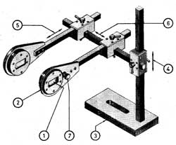
This set up has been designed to perform and verify the principles involved in study of vibrations. It consists of a basic frame and various components and sub assemblies designed for quick changeover and easy assembly of number of experiments in vibrations. A speed controller unit is provided for forced vibration experiments.
With this unit following experiments can be conducted
Pendulum Experiments
For Pendulum a sub frame is attached to upper beam. Two Chucks and Hardened V guide is provided for carrying experiments.
Experiment - 1 - Simple Pendulum
To verify the relation
LT = 2 pgand plot graph T Vs. L
Experiment - 2 - Compound Pendulum
Experiment - 3 - Bi-filler Suspension
( Tortional Oscillations) To determine the radius of gyration of body about the center of gravity by using relation
K LT = 2 pa gExperiment - 4 - Longitudanal Vibration
To verify the relation -
WT = 2 p Km x gand plot graph T Vs. W
Experiment - 5 - Equivalent spring mass system
Study of un damped natural vibrations of beam pivoted at one end supported by tension spring at the other end.
Experiment - 6 - Equivalent spring mass system
Study of undamped natural vibration of beam pivoted at one end supported by tension spring at the other end to plot a graph of amplitude verses frequency.
Experiment - 7 - Single Rotor
To verify the relation -
IT = 2 pKtand study the relationship between the periodic time and shaft length.
Experiment - 8 - Two Rotor
To verify the relation -
I A+ I B T = 2Kt (I A+ I B)and plot a graph F Vs. 1/ I1
Experiment - 9 - Single Rotor with viscous damping
To find out the damping coefficient Ct for various depths of damping drum (Immersed in oil) and to plot a graph of damping torque Vs. depth of damping drum.
Experiment - 10 - Dunkerley's Rule
To find out the natural frequency of a beam with and without load and to verify the Dunkerley's Rule.
Experiment - 11 - Forced Vibrations
To study the forced vibrations for various amount of damping and to plot a graph of amplitude verses frequency. Following accessories will be supplied along with unit. - Exciter unit with FHP motor and controller.Ordinary strip chart recorder.Damper with an arrangement for changing damping.

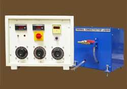
The apparatus consists of a copper sphere in which a mica heater is fitted. This small sphere is surrounded by another copper sphere and the insulating powder to be tested is filled in between these two spheres. The heat produced by heater is radially flows outwards in all directions through insulating powder. A digital temperature indicator is used to measure temperatures of Inner & Outer sphere. An ammeter & voltmeter is provided to measure heater input. By knowing heat input and temperatures, thermal conductivity of powder can be calculated. The unit is provided with asbestos powder, however any other powder can be tested with this unit.
Specifications:
Instrumentation & Controls :
Service Required :

It is motorised unit consisting of SUN gear mounted on input shaft, two plane gears meshes with the annular gear. These planet gears are mounted on a common arm to which output shaft is fitted. Loading arrangement is provided for loading the system and to measure Holding Torque.
Specifications:
Experiment :
Service Required :

The tilting flume is designed to conduct various experiments at various bed slopes from 1 in 25 in upstream to 1 in 25 on down stream. The flume has a perspex window to visualize the flow over models fixed in flume. The flume is provided with gates on upstream & downstream side to control the flow. Students can thus conduct the experiments and also visualize the flow. Various experiments like open channel flow study, specific energy curve, hydraulic jump, calibration of weirs, notches and venturi flume can be conducted.
Specifications:

The test rig consists of suitable equipment for performing experiments to measure the steam turbine efficiency, steam quality, and flow rate and condenser effectiveness. The turbine is suited for operation with a 300kg/hour, 10bar saturated steam supply.
With a steam flow rate of 300 kg/hour 10 kg/sq.cm saturated conditions, the turbine will produce Boiler Details:Steam Boiler of capacity 300 kg/hr., (made by Elite Boilers, Pune or equivalent) with working pressure of 15 kg/cm2 model STEAMPACK- 300 (f & a 30 C) LDO/HSD fired. As per ERECTION OF 300Kg/hour Boiler and Supply of accessories.
Other accessories required for the steam turbine test rig:1. A suitable sump tank of capacity at least 10, 000 liters is required for the condenser coolingwater supply. Existing lab sump if it is of sufficient capacity can be used for this purpose.Necessary GI piping to connect the condenser pump to the sump and the condenser and returntrenches are to be provided by the college.2. Necessary foundation for the turbine, condenser, and boiler.Optional: Cost of cooling tower (instead of the sump tank) Rs.55, 000(Rs. fifty five thousand only)
Feed Pump Motor, Blower Motor and oil Pump2) STEAM BOILER CONSTRUCTIONIt is designed on forced circulation Heat Exchange principle fabricated out of hightemperature resistant seamless tubes, once through spiral coil nest is arranged to give 3 clearpasses of flue gases forms combustion zone. It ensures for optimum rate of heat release andmaximum heat transfer and low stack temperature. It is ultimately placed in double shell onstudy steel frame for quick and easy installation.3) SHELL AND COIL ASSEMBLYInner & Outer shell, Aluminium foil in between two shells to act as heat retarder, Nestof once through spiral coil to give 3 clear pass and Top & Bottom refractory block.4) BURNER, BLOWER & OIL PUMP ASSEMBLYCentrifugal Blower coupled with motor, vertically downward position placed burnercomplete with nozzle, nozzle holder, diffuser plate, ignition electrodes, photocell, sight glass& solenoid valve. Gear oil pump coupled with motor, Oil filter and Pressure gauge.5) FEED WATER ASSEMBLYPositive displacement type piston pump coupled with motor, pulley, V-Belt, Pumpsafety valve & Non-return Valve.6) MOUNTINGS, FITTINGS & INSTRUMENTATIONMain steam stop valveSteam Auxiliary valveSafety ValveBlow down valveSteam trapNon return valveStrainerOil, water & steam pressure gauge with isolating valvesTemperature Indicator cum controllerFlue gas controllerSteam pressure switchAudio AlarmOil filerIgnition Transformer7) ELECTRICAL PANELIt is mounted on the front side of the boiler at a convenient height, is prewired andcomplete with starters, push buttons indicating lamps all duly labeled, fuses, O/L relays, contactors and sequence controller.8) ACCESSORIES
9) INSULATONThe steam line connecting the Turbine will be well insulated.10) FINISHRed oxide primer and one coat of enamel paint11) BASEStrong Channel Base, Houses all parts of boiler12) SOFTENERWater softener suitable for softening raw water up to 200 PPM of CaCO3 complete withinter connection piping, valves, Filter, Resin, Pressure Gauge, Ejector & brine tank13) Fuel Tank: 100 liter capacity MS fuel tank14) Feed water tank: 1000 liter capacity sintex tank15) Piping: Water line, fuel line, steam line (blow down line and line to connect boiler withturbine, etc)16) Thermal lagging for steam pipes17) Flue gas arrangement - Chimney 4 m height chimney