


Company Information
Ask for more detail from the seller
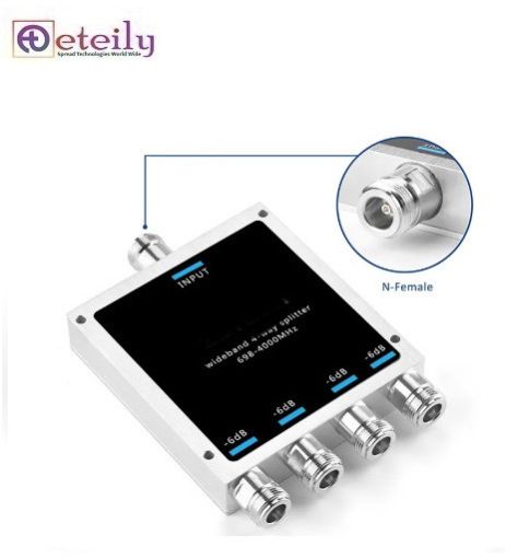
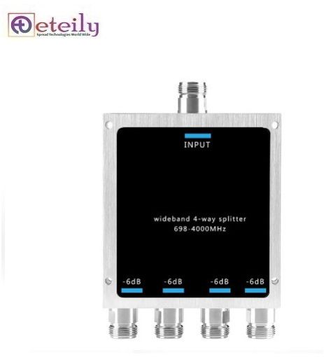
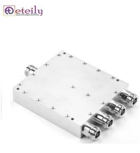
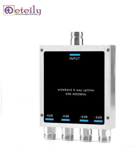
Contact SupplierThe specifications you've provided describe a multi-way splitter or power divider, often used in RF (Radio Frequency) communication systems. This component is commonly used in applications like GSM, Wi-Fi, cellular networks, and other RF systems where signals need to be split into multiple paths with minimal loss and interference. Below is a breakdown of the key characteristics and features based on the provided information: Key Specifications and Features: 1. Frequency Range: 698-4000 MHz (Microstrip) The splitter operates over a wide frequency range from 698 MHz to 4000 MHz, which covers a broad spectrum of wireless communication systems, including LTE, 5G, and GSM frequencies. The use of microstrip technology indicates that the splitter is likely designed with compact and efficient components, making it suitable for high-frequency, high-performance applications. 2. Split Way: The splitter supports different configurations, offering the ability to split the signal into 2, 3, 4, 6, or 8 output paths. This flexibility makes it suitable for different applications based on the number of signal paths required. 2-way split: Common for basic signal division. 3-way to 8-way split: Used in more complex setups where the same signal needs to be distributed to multiple devices or antennas. 3. VSWR (Voltage Standing Wave Ratio): ≤1.3:1 VSWR is a measure of the impedance matching between the splitter and the transmission line. A value of ≤1.3:1 indicates that the splitter has excellent impedance matching, meaning minimal signal reflection and maximum power transfer. This low VSWR ensures efficient signal transmission without significant losses. 4. Insertion Loss (dB): ≤0.9 dB (for the 2-way version), with values of up to ≤1.2 dB for 3-way, 4-way, 6-way, and 8-way splitters. Insertion loss refers to the amount of signal loss that occurs as the signal passes through the splitter. A lower insertion loss means the splitter is highly efficient, with minimal power loss when dividing the signal. 5. Split Loss (dB): Split loss increases with the number of output ports. The loss values are: ≤3.0 dB for 2-way ≤4.8 dB for 3-way ≤6.0 dB for 4-way ≤7.8 dB for 6-way ≤9.0 dB for 8-way Split loss represents the loss incurred when the signal is divided between multiple paths. The loss increases with more output ports since the input power is distributed among them. 6. Average Power (W): The maximum average power rating is 50 W. This indicates the amount of power the splitter can handle continuously without damage, making it suitable for most communication systems. 7. 3rd Order IMD (Intermodulation Distortion, dBc): ≤-140/-155/-160 dBc at 2x43 dBm. This represents the level of distortion created when two or more signals mix together, producing unwanted spurious signals. The low IMD values indicate that this splitter maintains a high level of linearity and minimal distortion, even at high power levels. 8. Impedance (Ω): The splitter has an impedance of 50 Ω, which is standard for most RF communication systems. Matching the impedance of the splitter to that of the system minimizes reflections and maximizes power transfer. 9. Connector Types: The splitter is compatible with several types of connectors, including: DIN 4.3-10 N-Female This flexibility allows the splitter to be used in a variety of system configurations and makes it compatible with a wide range of RF equipment. 10. Operating Temperature (℃): The device can operate in a temperature range of -35°C to +65°C, indicating it is suitable for both indoor and outdoor environments, and can withstand extreme temperature conditions. 11. Application: The splitter is designed for indoor or outdoor applications, making it versatile for use in a variety of installations, such as base stations, cellular networks, or other communication systems. 12. Finish: The splitter has a black-plated finish, which typically indicates a protective coating for durability, corrosion resistance, a


Connect with us