Our Product / Services
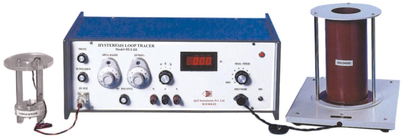
We offer the best product range of Study Of Second Order Networks, Handheld Gauss Meter, Function Generator, Travelling Microscope and Tesla Meter.


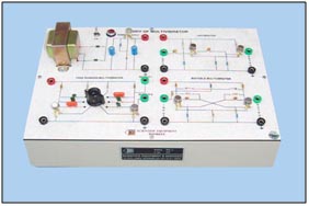
We offer Study of 741 Applications, Features Study of linear and non linear applications as: - Integrator - Differentiator - Summer - Subtractor - Voltage to Current converter - Current to Voltage converter - Astable Mode - Precision rectifier Built-in power supply Built-in square wave and triangular wave Generator Built-in current source. The set-up is so designed that no high voltage is exposed and hence safe in handling by the students.

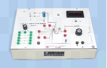
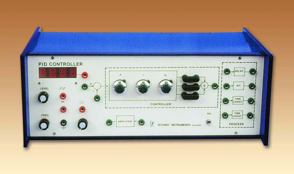
we offer compensation design useful for control labs. practical feedback control systems are often required to satisfy design specifications in the transient as well as steady state regions. cascade compensation is most commonly used for this purpose. this unit has been designed to enable the students to go through the complete design procedure and finally verify the performance improvements provided by compensation. the experimental set-up is accompanied by the supporting literature which becomes of vital importance as a major part of the experiment involves theoretical design of compensation networks. highlights >>design and test cascade compensator >>simulated system for accurate results >>built-in compensator only passive external components >>built-in signal sources experiments >>lag/lead compensation in the frequency domain >>lag/lead compensation in the s-plane >>all the above design problems may be undertaken for a very wide range of design specifications >>the implementation of the compensation network has been made very convenient by a pre wired amplifier with calibrated gain features and specifications >>simulated uncompensated system having adjustable damping. peak percent overshoot mp, variable from 20% to 50%, and steady state error variables from 50% to 0.5% >>compensation network implementation through built-in variable gain amplifier. gain is adjustable from 1 to 11 >>built-in square and sine wave generators for transient and frequency response studies. frequency adjustable from 25hz 800hz (approx.) >>essential accessory: a cro the experiment is complete in all respect, except a cro.