
Welcome to Albertel Technologies
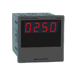
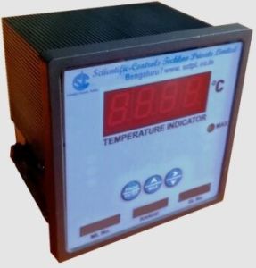
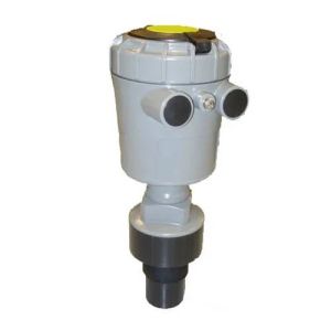
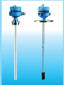
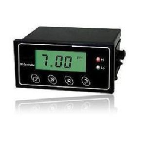
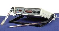
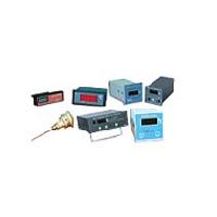
Manufacturer / Exporter / Supplier / Retailer Of Temperature Indicators, Process Indicator, Jumbo Process Indicator, Industrial Process Control Eqiupment, Digital Jumbo Indicators, Process Control Equipment, PH Online Controller, Process Control Equipments, Online PH Controller, PH Transmitters, Ca... Read More
-

Proprietor
Rosamma John
-

Year of Establishment
1998
-

Primary Business
Retailer
-

Number of Employees
6 - 20
-

Annual Turnover
Below Rs. 0.5 Crore Approx.