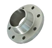
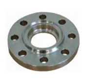
Post Buy Requirement
AT
Mumbai, Punjab, India
Add Review

Flanges #397541

Welded Flanges

Weld neck flanges are flanges in which welding is done on the neck of the flange thus giving its name weld neck flange. The design of weld neck flange is such that it reduces stress coming on the base of flange by transferring it on pipe thus transferring heavy concentration of pressure only on flange. The I.D of both pipe and flange matches there by reducing turbulence and erosion in the pipe due to continuous flow and stagnating particulates. Weld neck flanges are used in critical high pressure areas thus making it the most preferred butt weld flanges amongst all flanges. We are amongst the biggest exporters of weld neck flanges in India.
View Complete Details

Bronze Flange

Flanges are called threaded flanges as it is mounted on pipe with help of female threading on the line and male threading on the pipe line. Threaded flanges are used in lines where fast dismantling is required and threaded flanges are mainly used in low pressure in line. It can also be used at places where in welding is not possible due to exploding nature of line fluid. We are recognised as quality threaded flange manufacturer in India.
View Complete Details

Weld Neck Flanges

Weld neck flanges are flanges in which welding is done on the neck of the flange thus giving its name weld neck flange

DIMENSIONS OF CLASS 150 FLANGES (ANSI B 16.5) (in mm)
Nominal
Pipe Size
Flange
Dia
'O'
Dia of
Bolt Circle
'A'
Dia of Bolt Holes
'D'
No. of
Holes
Thk of Flange
'C'
Diameter at Weld Bevel Dia of Hub
'E'
Length Through Hub Bore 'B' Dia of
R/F
R
Depth of
Socket
F
Length
of
Threading
S/O & S/W
Y
W/N
Y
L/J
Y
S/O & S/W
B
L/J
B
1/2'' 15 88.9 60.3 15.9 4 11.1 21.3 30.2 15.9 47.6 15.9 22.3 22.9 34.9 9.5 15.9
3/4'' 20 98.4 69.8 15.9 4 12.7 26.7 38.1 15.9 52.4 15.9 27.7 28.2 42.9 11.1 15.9
1'' 25 107.9 79.4 15.9 4 14.3 33.5 49.2 17.5 55.6 17.5 34.5 35.0 50.8 12.7 17.5
1 ¼'' 32 117.5 88.9 15.9 4 15.9 42.2 58.7 20.6 57.1 20.6 43.2 43.7 63.5 14.3 20.6
1 ½'' 40 127.0 98.4 15.9 4 17.5 48.3 65.1 22.2 61.9 22.2 49.5 50.0 73.0 15.9 22.2
2'' 50 152.4 120.6 19.0 4 19.0 60.4 77.8 25.4 63.5 25.4 62.0 62.5 92.1 17.5 25.4
2 ½'' 65 177.8 139.7 19.0 4 22.2 73.1 90.5 28.6 69.8 28.6 74.7 75.4 104.8 19.0 28.6
3'' 80 190.5 152.4 19.0 4 23.8 88.9 107.9 30.2 69.8 30.2 90.7 91.4 127.0 20.6 30.2
3 ½'' 90 216.0 177.8 19.0 8 23.8 101.6 122.2 31.7 71.4 31.7 103.4 104.1 140.0 20.6 31.7
4'' 100 228.6 190.5 19.0 8 23.8 114.3 134.9 33.3 76.2 33.3 116.1 116.8 157.2 23.8 33.3
5'' 125 254.0 215.9 22.2 8 23.8 141.2 163.5 36.5 88.9 36.5 143.8 144.5 185.7 23.8 36.5
6'' 150 279.4 241.3 22.2 8 25.4 168.4 192.1 39.7 88.9 39.7 170.7 171.4 215.9 27.0 39.7
8'' 200 342.9 298.4 22.2 8 28.6 219.2 246.1 44.4 101.6 44.4 221.5 222.2 269.9 31.7 44.4
10'' 250 406.4 361.9 25.4 12 30.2 273.0 304.8 49.2 101.6 49.2 276.3 277.4 323.8 33.3 49.2
12'' 300 482.6 431.8 25.4 12 31.8 323.8 365.1 55.6 114.3 55.6 327.1 328.2 381.0 39.7 55.6
14'' 350 533.4 476.2 28.6 12 34.9 355.6 400.0 57.1 127.0 79.4 359.1 360.2 412.7 41.3 57.1
16'' 400 596.9 539.7 28.6 16 36.5 406.4 457.2 63.5 127.0 87.3 410.5 411.2 469.9 44.4 63.5
18'' 450 635.0 577.8 31.7 16 39.7 457.2 504.8 68.3 139.7 96.8 461.8 462.3 533.4 49.2 68.3
20'' 500 698.5 635.0 31.7 20 42.9 508.0 558.8 73.0 144.5 103.2 513.1 514.3 584.2 54.0 73.0
24'' 600 812.8 749.3 34.9 20 47.6 609.6 663.6 82.5 152.4 111.1 615.9 615.9 692.1 63.5 82.5


View Complete Details

Slip On Flanges

SIip on flanges derives its name Slip-on as pipe slips in to the flange prior to welding as slip-on flanges are bored slightly larger then the outside diameter of the pipe.

DIMENSIONS OF CLASS 150 FLANGES (ANSI B 16.5) (in mm)
Nominal
Pipe Size
Flange
Dia
'O'
Dia of
Bolt Circle
'A'
Dia of Bolt Holes
'D'
No. of
Holes
Thk of Flange
'C'
Diameter at Weld Bevel Dia of Hub
'E'
Length Through Hub Bore 'B' Dia of
R/F
R
Depth of
Socket
F
Length
of
Threading
S/O & S/W
Y
W/N
Y
L/J
Y
S/O & S/W
B
L/J
B
1/2'' 15 88.9 60.3 15.9 4 11.1 21.3 30.2 15.9 47.6 15.9 22.3 22.9 34.9 9.5 15.9
3/4'' 20 98.4 69.8 15.9 4 12.7 26.7 38.1 15.9 52.4 15.9 27.7 28.2 42.9 11.1 15.9
1'' 25 107.9 79.4 15.9 4 14.3 33.5 49.2 17.5 55.6 17.5 34.5 35.0 50.8 12.7 17.5
1 ¼'' 32 117.5 88.9 15.9 4 15.9 42.2 58.7 20.6 57.1 20.6 43.2 43.7 63.5 14.3 20.6
1 ½'' 40 127.0 98.4 15.9 4 17.5 48.3 65.1 22.2 61.9 22.2 49.5 50.0 73.0 15.9 22.2
2'' 50 152.4 120.6 19.0 4 19.0 60.4 77.8 25.4 63.5 25.4 62.0 62.5 92.1 17.5 25.4
2 ½'' 65 177.8 139.7 19.0 4 22.2 73.1 90.5 28.6 69.8 28.6 74.7 75.4 104.8 19.0 28.6
3'' 80 190.5 152.4 19.0 4 23.8 88.9 107.9 30.2 69.8 30.2 90.7 91.4 127.0 20.6 30.2
3 ½'' 90 216.0 177.8 19.0 8 23.8 101.6 122.2 31.7 71.4 31.7 103.4 104.1 140.0 20.6 31.7
4'' 100 228.6 190.5 19.0 8 23.8 114.3 134.9 33.3 76.2 33.3 116.1 116.8 157.2 23.8 33.3
5'' 125 254.0 215.9 22.2 8 23.8 141.2 163.5 36.5 88.9 36.5 143.8 144.5 185.7 23.8 36.5
6'' 150 279.4 241.3 22.2 8 25.4 168.4 192.1 39.7 88.9 39.7 170.7 171.4 215.9 27.0 39.7
8'' 200 342.9 298.4 22.2 8 28.6 219.2 246.1 44.4 101.6 44.4 221.5 222.2 269.9 31.7 44.4
10'' 250 406.4 361.9 25.4 12 30.2 273.0 304.8 49.2 101.6 49.2 276.3 277.4 323.8 33.3 49.2
12'' 300 482.6 431.8 25.4 12 31.8 323.8 365.1 55.6 114.3 55.6 327.1 328.2 381.0 39.7 55.6
14'' 350 533.4 476.2 28.6 12 34.9 355.6 400.0 57.1 127.0 79.4 359.1 360.2 412.7 41.3 57.1
16'' 400 596.9 539.7 28.6 16 36.5 406.4 457.2 63.5 127.0 87.3 410.5 411.2 469.9 44.4 63.5
18'' 450 635.0 577.8 31.7 16 39.7 457.2 504.8 68.3 139.7 96.8 461.8 462.3 533.4 49.2 68.3
20'' 500 698.5 635.0 31.7 20 42.9 508.0 558.8 73.0 144.5 103.2 513.1 514.3 584.2 54.0 73.0
24'' 600 812.8 749.3 34.9 20 47.6 609.6 663.6 82.5 152.4 111.1 615.9 615.9 692.1 63.5 82.5


View Complete Details

Blind Flanges

A Blind flange derived it name blind as it is used to blank off a line it does not have a inside bore it is mounted on corresponding flange with the help of Bolt holes matching with that of the other flange.

DIMENSIONS OF CLASS 150 FLANGES (ANSI B 16.5) (in mm)
Nominal
Pipe Size
Flange
Dia
'O'
Dia of
Bolt Circle
'A'
Dia of Bolt Holes
'D'
No. of
Holes
Thk of Flange
'C'
Diameter at Weld Bevel Dia of Hub
'E'
Length Through Hub Bore 'B' Dia of
R/F
R
Depth of
Socket
F
Length
of
Threading
S/O & S/W
Y
W/N
Y
L/J
Y
S/O & S/W
B
L/J
B
1/2'' 15 88.9 60.3 15.9 4 11.1 21.3 30.2 15.9 47.6 15.9 22.3 22.9 34.9 9.5 15.9
3/4'' 20 98.4 69.8 15.9 4 12.7 26.7 38.1 15.9 52.4 15.9 27.7 28.2 42.9 11.1 15.9
1'' 25 107.9 79.4 15.9 4 14.3 33.5 49.2 17.5 55.6 17.5 34.5 35.0 50.8 12.7 17.5
1 ¼'' 32 117.5 88.9 15.9 4 15.9 42.2 58.7 20.6 57.1 20.6 43.2 43.7 63.5 14.3 20.6
1 ½'' 40 127.0 98.4 15.9 4 17.5 48.3 65.1 22.2 61.9 22.2 49.5 50.0 73.0 15.9 22.2
2'' 50 152.4 120.6 19.0 4 19.0 60.4 77.8 25.4 63.5 25.4 62.0 62.5 92.1 17.5 25.4
2 ½'' 65 177.8 139.7 19.0 4 22.2 73.1 90.5 28.6 69.8 28.6 74.7 75.4 104.8 19.0 28.6
3'' 80 190.5 152.4 19.0 4 23.8 88.9 107.9 30.2 69.8 30.2 90.7 91.4 127.0 20.6 30.2
3 ½'' 90 216.0 177.8 19.0 8 23.8 101.6 122.2 31.7 71.4 31.7 103.4 104.1 140.0 20.6 31.7
4'' 100 228.6 190.5 19.0 8 23.8 114.3 134.9 33.3 76.2 33.3 116.1 116.8 157.2 23.8 33.3
5'' 125 254.0 215.9 22.2 8 23.8 141.2 163.5 36.5 88.9 36.5 143.8 144.5 185.7 23.8 36.5
6'' 150 279.4 241.3 22.2 8 25.4 168.4 192.1 39.7 88.9 39.7 170.7 171.4 215.9 27.0 39.7
8'' 200 342.9 298.4 22.2 8 28.6 219.2 246.1 44.4 101.6 44.4 221.5 222.2 269.9 31.7 44.4
10'' 250 406.4 361.9 25.4 12 30.2 273.0 304.8 49.2 101.6 49.2 276.3 277.4 323.8 33.3 49.2
12'' 300 482.6 431.8 25.4 12 31.8 323.8 365.1 55.6 114.3 55.6 327.1 328.2 381.0 39.7 55.6
14'' 350 533.4 476.2 28.6 12 34.9 355.6 400.0 57.1 127.0 79.4 359.1 360.2 412.7 41.3 57.1
16'' 400 596.9 539.7 28.6 16 36.5 406.4 457.2 63.5 127.0 87.3 410.5 411.2 469.9 44.4 63.5
18'' 450 635.0 577.8 31.7 16 39.7 457.2 504.8 68.3 139.7 96.8 461.8 462.3 533.4 49.2 68.3
20'' 500 698.5 635.0 31.7 20 42.9 508.0 558.8 73.0 144.5 103.2 513.1 514.3 584.2 54.0 73.0
24'' 600 812.8 749.3 34.9 20 47.6 609.6 663.6 82.5 152.4 111.1 615.9 615.9 692.1 63.5 82.5


View Complete Details

Lap Joint Flanges

The lap joint flange derived it name lap joint as it is to be joint with a joint stub end. The flange has curved radius at its bore to accommodate a lap joint stub.

DIMENSIONS OF CLASS 150 FLANGES (ANSI B 16.5) (in mm)
Nominal
Pipe Size
Flange
Dia
'O'
Dia of
Bolt Circle
'A'
Dia of Bolt Holes
'D'
No. of
Holes
Thk of Flange
'C'
Diameter at Weld Bevel Dia of Hub
'E'
Length Through Hub Bore 'B' Dia of
R/F
R
Depth of
Socket
F
Length
of
Threading
S/O & S/W
Y
W/N
Y
L/J
Y
S/O & S/W
B
L/J
B
1/2'' 15 88.9 60.3 15.9 4 11.1 21.3 30.2 15.9 47.6 15.9 22.3 22.9 34.9 9.5 15.9
3/4'' 20 98.4 69.8 15.9 4 12.7 26.7 38.1 15.9 52.4 15.9 27.7 28.2 42.9 11.1 15.9
1'' 25 107.9 79.4 15.9 4 14.3 33.5 49.2 17.5 55.6 17.5 34.5 35.0 50.8 12.7 17.5
1 ¼'' 32 117.5 88.9 15.9 4 15.9 42.2 58.7 20.6 57.1 20.6 43.2 43.7 63.5 14.3 20.6
1 ½'' 40 127.0 98.4 15.9 4 17.5 48.3 65.1 22.2 61.9 22.2 49.5 50.0 73.0 15.9 22.2
2'' 50 152.4 120.6 19.0 4 19.0 60.4 77.8 25.4 63.5 25.4 62.0 62.5 92.1 17.5 25.4
2 ½'' 65 177.8 139.7 19.0 4 22.2 73.1 90.5 28.6 69.8 28.6 74.7 75.4 104.8 19.0 28.6
3'' 80 190.5 152.4 19.0 4 23.8 88.9 107.9 30.2 69.8 30.2 90.7 91.4 127.0 20.6 30.2
3 ½'' 90 216.0 177.8 19.0 8 23.8 101.6 122.2 31.7 71.4 31.7 103.4 104.1 140.0 20.6 31.7
4'' 100 228.6 190.5 19.0 8 23.8 114.3 134.9 33.3 76.2 33.3 116.1 116.8 157.2 23.8 33.3
5'' 125 254.0 215.9 22.2 8 23.8 141.2 163.5 36.5 88.9 36.5 143.8 144.5 185.7 23.8 36.5
6'' 150 279.4 241.3 22.2 8 25.4 168.4 192.1 39.7 88.9 39.7 170.7 171.4 215.9 27.0 39.7
8'' 200 342.9 298.4 22.2 8 28.6 219.2 246.1 44.4 101.6 44.4 221.5 222.2 269.9 31.7 44.4
10'' 250 406.4 361.9 25.4 12 30.2 273.0 304.8 49.2 101.6 49.2 276.3 277.4 323.8 33.3 49.2
12'' 300 482.6 431.8 25.4 12 31.8 323.8 365.1 55.6 114.3 55.6 327.1 328.2 381.0 39.7 55.6
14'' 350 533.4 476.2 28.6 12 34.9 355.6 400.0 57.1 127.0 79.4 359.1 360.2 412.7 41.3 57.1
16'' 400 596.9 539.7 28.6 16 36.5 406.4 457.2 63.5 127.0 87.3 410.5 411.2 469.9 44.4 63.5
18'' 450 635.0 577.8 31.7 16 39.7 457.2 504.8 68.3 139.7 96.8 461.8 462.3 533.4 49.2 68.3
20'' 500 698.5 635.0 31.7 20 42.9 508.0 558.8 73.0 144.5 103.2 513.1 514.3 584.2 54.0 73.0
24'' 600 812.8 749.3 34.9 20 47.6 609.6 663.6 82.5 152.4 111.1 615.9 615.9 692.1 63.5 82.5


View Complete Details

Socket Weld Flanges

The socket welding flange derives it name socket weld as the flange has bore and counter bore where in the matching pipe slips on.

DIMENSIONS OF CLASS 150 FLANGES (ANSI B 16.5) (in mm)
Nominal
Pipe Size
Flange
Dia
'O'
Dia of
Bolt Circle
'A'
Dia of Bolt Holes
'D'
No. of
Holes
Thk of Flange
'C'
Diameter at Weld Bevel Dia of Hub
'E'
Length Through Hub Bore 'B' Dia of
R/F
R
Depth of
Socket
F
Length
of
Threading
S/O & S/W
Y
W/N
Y
L/J
Y
S/O & S/W
B
L/J
B
1/2'' 15 88.9 60.3 15.9 4 11.1 21.3 30.2 15.9 47.6 15.9 22.3 22.9 34.9 9.5 15.9
3/4'' 20 98.4 69.8 15.9 4 12.7 26.7 38.1 15.9 52.4 15.9 27.7 28.2 42.9 11.1 15.9
1'' 25 107.9 79.4 15.9 4 14.3 33.5 49.2 17.5 55.6 17.5 34.5 35.0 50.8 12.7 17.5
1 ¼'' 32 117.5 88.9 15.9 4 15.9 42.2 58.7 20.6 57.1 20.6 43.2 43.7 63.5 14.3 20.6
1 ½'' 40 127.0 98.4 15.9 4 17.5 48.3 65.1 22.2 61.9 22.2 49.5 50.0 73.0 15.9 22.2
2'' 50 152.4 120.6 19.0 4 19.0 60.4 77.8 25.4 63.5 25.4 62.0 62.5 92.1 17.5 25.4
2 ½'' 65 177.8 139.7 19.0 4 22.2 73.1 90.5 28.6 69.8 28.6 74.7 75.4 104.8 19.0 28.6
3'' 80 190.5 152.4 19.0 4 23.8 88.9 107.9 30.2 69.8 30.2 90.7 91.4 127.0 20.6 30.2
3 ½'' 90 216.0 177.8 19.0 8 23.8 101.6 122.2 31.7 71.4 31.7 103.4 104.1 140.0 20.6 31.7
4'' 100 228.6 190.5 19.0 8 23.8 114.3 134.9 33.3 76.2 33.3 116.1 116.8 157.2 23.8 33.3
5'' 125 254.0 215.9 22.2 8 23.8 141.2 163.5 36.5 88.9 36.5 143.8 144.5 185.7 23.8 36.5
6'' 150 279.4 241.3 22.2 8 25.4 168.4 192.1 39.7 88.9 39.7 170.7 171.4 215.9 27.0 39.7
8'' 200 342.9 298.4 22.2 8 28.6 219.2 246.1 44.4 101.6 44.4 221.5 222.2 269.9 31.7 44.4
10'' 250 406.4 361.9 25.4 12 30.2 273.0 304.8 49.2 101.6 49.2 276.3 277.4 323.8 33.3 49.2
12'' 300 482.6 431.8 25.4 12 31.8 323.8 365.1 55.6 114.3 55.6 327.1 328.2 381.0 39.7 55.6
14'' 350 533.4 476.2 28.6 12 34.9 355.6 400.0 57.1 127.0 79.4 359.1 360.2 412.7 41.3 57.1
16'' 400 596.9 539.7 28.6 16 36.5 406.4 457.2 63.5 127.0 87.3 410.5 411.2 469.9 44.4 63.5
18'' 450 635.0 577.8 31.7 16 39.7 457.2 504.8 68.3 139.7 96.8 461.8 462.3 533.4 49.2 68.3
20'' 500 698.5 635.0 31.7 20 42.9 508.0 558.8 73.0 144.5 103.2 513.1 514.3 584.2 54.0 73.0
24'' 600 812.8 749.3 34.9 20 47.6 609.6 663.6 82.5 152.4 111.1 615.9 615.9 692.1 63.5 82.5


View Complete Details

Threaded Flanges

Flanges are called threaded flanges as it is mounted on pipe with help of female threading on the line and male threading on the pipe line

DIMENSIONS OF CLASS 150 FLANGES (ANSI B 16.5) (in mm)
Nominal
Pipe Size
Flange
Dia
'O'
Dia of
Bolt Circle
'A'
Dia of Bolt Holes
'D'
No. of
Holes
Thk of Flange
'C'
Diameter at Weld Bevel Dia of Hub
'E'
Length Through Hub Bore 'B' Dia of
R/F
R
Depth of
Socket
F
Length
of
Threading
S/O & S/W
Y
W/N
Y
L/J
Y
S/O & S/W
B
L/J
B
1/2'' 15 88.9 60.3 15.9 4 11.1 21.3 30.2 15.9 47.6 15.9 22.3 22.9 34.9 9.5 15.9
3/4'' 20 98.4 69.8 15.9 4 12.7 26.7 38.1 15.9 52.4 15.9 27.7 28.2 42.9 11.1 15.9
1'' 25 107.9 79.4 15.9 4 14.3 33.5 49.2 17.5 55.6 17.5 34.5 35.0 50.8 12.7 17.5
1 ¼'' 32 117.5 88.9 15.9 4 15.9 42.2 58.7 20.6 57.1 20.6 43.2 43.7 63.5 14.3 20.6
1 ½'' 40 127.0 98.4 15.9 4 17.5 48.3 65.1 22.2 61.9 22.2 49.5 50.0 73.0 15.9 22.2
2'' 50 152.4 120.6 19.0 4 19.0 60.4 77.8 25.4 63.5 25.4 62.0 62.5 92.1 17.5 25.4
2 ½'' 65 177.8 139.7 19.0 4 22.2 73.1 90.5 28.6 69.8 28.6 74.7 75.4 104.8 19.0 28.6
3'' 80 190.5 152.4 19.0 4 23.8 88.9 107.9 30.2 69.8 30.2 90.7 91.4 127.0 20.6 30.2
3 ½'' 90 216.0 177.8 19.0 8 23.8 101.6 122.2 31.7 71.4 31.7 103.4 104.1 140.0 20.6 31.7
4'' 100 228.6 190.5 19.0 8 23.8 114.3 134.9 33.3 76.2 33.3 116.1 116.8 157.2 23.8 33.3
5'' 125 254.0 215.9 22.2 8 23.8 141.2 163.5 36.5 88.9 36.5 143.8 144.5 185.7 23.8 36.5
6'' 150 279.4 241.3 22.2 8 25.4 168.4 192.1 39.7 88.9 39.7 170.7 171.4 215.9 27.0 39.7
8'' 200 342.9 298.4 22.2 8 28.6 219.2 246.1 44.4 101.6 44.4 221.5 222.2 269.9 31.7 44.4
10'' 250 406.4 361.9 25.4 12 30.2 273.0 304.8 49.2 101.6 49.2 276.3 277.4 323.8 33.3 49.2
12'' 300 482.6 431.8 25.4 12 31.8 323.8 365.1 55.6 114.3 55.6 327.1 328.2 381.0 39.7 55.6
14'' 350 533.4 476.2 28.6 12 34.9 355.6 400.0 57.1 127.0 79.4 359.1 360.2 412.7 41.3 57.1
16'' 400 596.9 539.7 28.6 16 36.5 406.4 457.2 63.5 127.0 87.3 410.5 411.2 469.9 44.4 63.5
18'' 450 635.0 577.8 31.7 16 39.7 457.2 504.8 68.3 139.7 96.8 461.8 462.3 533.4 49.2 68.3
20'' 500 698.5 635.0 31.7 20 42.9 508.0 558.8 73.0 144.5 103.2 513.1 514.3 584.2 54.0 73.0
24'' 600 812.8 749.3 34.9 20 47.6 609.6 663.6 82.5 152.4 111.1 615.9 615.9 692.1 63.5 82.5


View Complete Details
Tell Us What are you looking for? Will call you back

Contact Us

  • HIREN PANCHAL (AMBUJA Tube Fitting)
  • 23, Dhumal House, Gala No. 03, Ground Floor, 1st Carpenter Street, Mumbai - 400 004., Bhuleshwar, Punjab, India
  • Share us via
Retailer of Flanges from Mumbai, Punjab by AMBUJA Tube Fitting
Post Buy Requirement
AT
Mumbai, Punjab, India
Add Review

Flanges #397541

Welded Flanges

Weld neck flanges are flanges in which welding is done on the neck of the flange thus giving its name weld neck flange. The design of weld neck flange is such that it reduces stress coming on the base of flange by transferring it on pipe thus transferring heavy concentration of pressure only on flange. The I.D of both pipe and flange matches there by reducing turbulence and erosion in the pipe due to continuous flow and stagnating particulates. Weld neck flanges are used in critical high pressure areas thus making it the most preferred butt weld flanges amongst all flanges. We are amongst the biggest exporters of weld neck flanges in India.
View Complete Details

Bronze Flange

Flanges are called threaded flanges as it is mounted on pipe with help of female threading on the line and male threading on the pipe line. Threaded flanges are used in lines where fast dismantling is required and threaded flanges are mainly used in low pressure in line. It can also be used at places where in welding is not possible due to exploding nature of line fluid. We are recognised as quality threaded flange manufacturer in India.
View Complete Details

Weld Neck Flanges

Weld neck flanges are flanges in which welding is done on the neck of the flange thus giving its name weld neck flange

DIMENSIONS OF CLASS 150 FLANGES (ANSI B 16.5) (in mm)
Nominal
Pipe Size
Flange
Dia
'O'
Dia of
Bolt Circle
'A'
Dia of Bolt Holes
'D'
No. of
Holes
Thk of Flange
'C'
Diameter at Weld Bevel Dia of Hub
'E'
Length Through Hub Bore 'B' Dia of
R/F
R
Depth of
Socket
F
Length
of
Threading
S/O & S/W
Y
W/N
Y
L/J
Y
S/O & S/W
B
L/J
B
1/2'' 15 88.9 60.3 15.9 4 11.1 21.3 30.2 15.9 47.6 15.9 22.3 22.9 34.9 9.5 15.9
3/4'' 20 98.4 69.8 15.9 4 12.7 26.7 38.1 15.9 52.4 15.9 27.7 28.2 42.9 11.1 15.9
1'' 25 107.9 79.4 15.9 4 14.3 33.5 49.2 17.5 55.6 17.5 34.5 35.0 50.8 12.7 17.5
1 ¼'' 32 117.5 88.9 15.9 4 15.9 42.2 58.7 20.6 57.1 20.6 43.2 43.7 63.5 14.3 20.6
1 ½'' 40 127.0 98.4 15.9 4 17.5 48.3 65.1 22.2 61.9 22.2 49.5 50.0 73.0 15.9 22.2
2'' 50 152.4 120.6 19.0 4 19.0 60.4 77.8 25.4 63.5 25.4 62.0 62.5 92.1 17.5 25.4
2 ½'' 65 177.8 139.7 19.0 4 22.2 73.1 90.5 28.6 69.8 28.6 74.7 75.4 104.8 19.0 28.6
3'' 80 190.5 152.4 19.0 4 23.8 88.9 107.9 30.2 69.8 30.2 90.7 91.4 127.0 20.6 30.2
3 ½'' 90 216.0 177.8 19.0 8 23.8 101.6 122.2 31.7 71.4 31.7 103.4 104.1 140.0 20.6 31.7
4'' 100 228.6 190.5 19.0 8 23.8 114.3 134.9 33.3 76.2 33.3 116.1 116.8 157.2 23.8 33.3
5'' 125 254.0 215.9 22.2 8 23.8 141.2 163.5 36.5 88.9 36.5 143.8 144.5 185.7 23.8 36.5
6'' 150 279.4 241.3 22.2 8 25.4 168.4 192.1 39.7 88.9 39.7 170.7 171.4 215.9 27.0 39.7
8'' 200 342.9 298.4 22.2 8 28.6 219.2 246.1 44.4 101.6 44.4 221.5 222.2 269.9 31.7 44.4
10'' 250 406.4 361.9 25.4 12 30.2 273.0 304.8 49.2 101.6 49.2 276.3 277.4 323.8 33.3 49.2
12'' 300 482.6 431.8 25.4 12 31.8 323.8 365.1 55.6 114.3 55.6 327.1 328.2 381.0 39.7 55.6
14'' 350 533.4 476.2 28.6 12 34.9 355.6 400.0 57.1 127.0 79.4 359.1 360.2 412.7 41.3 57.1
16'' 400 596.9 539.7 28.6 16 36.5 406.4 457.2 63.5 127.0 87.3 410.5 411.2 469.9 44.4 63.5
18'' 450 635.0 577.8 31.7 16 39.7 457.2 504.8 68.3 139.7 96.8 461.8 462.3 533.4 49.2 68.3
20'' 500 698.5 635.0 31.7 20 42.9 508.0 558.8 73.0 144.5 103.2 513.1 514.3 584.2 54.0 73.0
24'' 600 812.8 749.3 34.9 20 47.6 609.6 663.6 82.5 152.4 111.1 615.9 615.9 692.1 63.5 82.5


View Complete Details

Slip On Flanges

SIip on flanges derives its name Slip-on as pipe slips in to the flange prior to welding as slip-on flanges are bored slightly larger then the outside diameter of the pipe.

DIMENSIONS OF CLASS 150 FLANGES (ANSI B 16.5) (in mm)
Nominal
Pipe Size
Flange
Dia
'O'
Dia of
Bolt Circle
'A'
Dia of Bolt Holes
'D'
No. of
Holes
Thk of Flange
'C'
Diameter at Weld Bevel Dia of Hub
'E'
Length Through Hub Bore 'B' Dia of
R/F
R
Depth of
Socket
F
Length
of
Threading
S/O & S/W
Y
W/N
Y
L/J
Y
S/O & S/W
B
L/J
B
1/2'' 15 88.9 60.3 15.9 4 11.1 21.3 30.2 15.9 47.6 15.9 22.3 22.9 34.9 9.5 15.9
3/4'' 20 98.4 69.8 15.9 4 12.7 26.7 38.1 15.9 52.4 15.9 27.7 28.2 42.9 11.1 15.9
1'' 25 107.9 79.4 15.9 4 14.3 33.5 49.2 17.5 55.6 17.5 34.5 35.0 50.8 12.7 17.5
1 ¼'' 32 117.5 88.9 15.9 4 15.9 42.2 58.7 20.6 57.1 20.6 43.2 43.7 63.5 14.3 20.6
1 ½'' 40 127.0 98.4 15.9 4 17.5 48.3 65.1 22.2 61.9 22.2 49.5 50.0 73.0 15.9 22.2
2'' 50 152.4 120.6 19.0 4 19.0 60.4 77.8 25.4 63.5 25.4 62.0 62.5 92.1 17.5 25.4
2 ½'' 65 177.8 139.7 19.0 4 22.2 73.1 90.5 28.6 69.8 28.6 74.7 75.4 104.8 19.0 28.6
3'' 80 190.5 152.4 19.0 4 23.8 88.9 107.9 30.2 69.8 30.2 90.7 91.4 127.0 20.6 30.2
3 ½'' 90 216.0 177.8 19.0 8 23.8 101.6 122.2 31.7 71.4 31.7 103.4 104.1 140.0 20.6 31.7
4'' 100 228.6 190.5 19.0 8 23.8 114.3 134.9 33.3 76.2 33.3 116.1 116.8 157.2 23.8 33.3
5'' 125 254.0 215.9 22.2 8 23.8 141.2 163.5 36.5 88.9 36.5 143.8 144.5 185.7 23.8 36.5
6'' 150 279.4 241.3 22.2 8 25.4 168.4 192.1 39.7 88.9 39.7 170.7 171.4 215.9 27.0 39.7
8'' 200 342.9 298.4 22.2 8 28.6 219.2 246.1 44.4 101.6 44.4 221.5 222.2 269.9 31.7 44.4
10'' 250 406.4 361.9 25.4 12 30.2 273.0 304.8 49.2 101.6 49.2 276.3 277.4 323.8 33.3 49.2
12'' 300 482.6 431.8 25.4 12 31.8 323.8 365.1 55.6 114.3 55.6 327.1 328.2 381.0 39.7 55.6
14'' 350 533.4 476.2 28.6 12 34.9 355.6 400.0 57.1 127.0 79.4 359.1 360.2 412.7 41.3 57.1
16'' 400 596.9 539.7 28.6 16 36.5 406.4 457.2 63.5 127.0 87.3 410.5 411.2 469.9 44.4 63.5
18'' 450 635.0 577.8 31.7 16 39.7 457.2 504.8 68.3 139.7 96.8 461.8 462.3 533.4 49.2 68.3
20'' 500 698.5 635.0 31.7 20 42.9 508.0 558.8 73.0 144.5 103.2 513.1 514.3 584.2 54.0 73.0
24'' 600 812.8 749.3 34.9 20 47.6 609.6 663.6 82.5 152.4 111.1 615.9 615.9 692.1 63.5 82.5


View Complete Details

Blind Flanges

A Blind flange derived it name blind as it is used to blank off a line it does not have a inside bore it is mounted on corresponding flange with the help of Bolt holes matching with that of the other flange.

DIMENSIONS OF CLASS 150 FLANGES (ANSI B 16.5) (in mm)
Nominal
Pipe Size
Flange
Dia
'O'
Dia of
Bolt Circle
'A'
Dia of Bolt Holes
'D'
No. of
Holes
Thk of Flange
'C'
Diameter at Weld Bevel Dia of Hub
'E'
Length Through Hub Bore 'B' Dia of
R/F
R
Depth of
Socket
F
Length
of
Threading
S/O & S/W
Y
W/N
Y
L/J
Y
S/O & S/W
B
L/J
B
1/2'' 15 88.9 60.3 15.9 4 11.1 21.3 30.2 15.9 47.6 15.9 22.3 22.9 34.9 9.5 15.9
3/4'' 20 98.4 69.8 15.9 4 12.7 26.7 38.1 15.9 52.4 15.9 27.7 28.2 42.9 11.1 15.9
1'' 25 107.9 79.4 15.9 4 14.3 33.5 49.2 17.5 55.6 17.5 34.5 35.0 50.8 12.7 17.5
1 ¼'' 32 117.5 88.9 15.9 4 15.9 42.2 58.7 20.6 57.1 20.6 43.2 43.7 63.5 14.3 20.6
1 ½'' 40 127.0 98.4 15.9 4 17.5 48.3 65.1 22.2 61.9 22.2 49.5 50.0 73.0 15.9 22.2
2'' 50 152.4 120.6 19.0 4 19.0 60.4 77.8 25.4 63.5 25.4 62.0 62.5 92.1 17.5 25.4
2 ½'' 65 177.8 139.7 19.0 4 22.2 73.1 90.5 28.6 69.8 28.6 74.7 75.4 104.8 19.0 28.6
3'' 80 190.5 152.4 19.0 4 23.8 88.9 107.9 30.2 69.8 30.2 90.7 91.4 127.0 20.6 30.2
3 ½'' 90 216.0 177.8 19.0 8 23.8 101.6 122.2 31.7 71.4 31.7 103.4 104.1 140.0 20.6 31.7
4'' 100 228.6 190.5 19.0 8 23.8 114.3 134.9 33.3 76.2 33.3 116.1 116.8 157.2 23.8 33.3
5'' 125 254.0 215.9 22.2 8 23.8 141.2 163.5 36.5 88.9 36.5 143.8 144.5 185.7 23.8 36.5
6'' 150 279.4 241.3 22.2 8 25.4 168.4 192.1 39.7 88.9 39.7 170.7 171.4 215.9 27.0 39.7
8'' 200 342.9 298.4 22.2 8 28.6 219.2 246.1 44.4 101.6 44.4 221.5 222.2 269.9 31.7 44.4
10'' 250 406.4 361.9 25.4 12 30.2 273.0 304.8 49.2 101.6 49.2 276.3 277.4 323.8 33.3 49.2
12'' 300 482.6 431.8 25.4 12 31.8 323.8 365.1 55.6 114.3 55.6 327.1 328.2 381.0 39.7 55.6
14'' 350 533.4 476.2 28.6 12 34.9 355.6 400.0 57.1 127.0 79.4 359.1 360.2 412.7 41.3 57.1
16'' 400 596.9 539.7 28.6 16 36.5 406.4 457.2 63.5 127.0 87.3 410.5 411.2 469.9 44.4 63.5
18'' 450 635.0 577.8 31.7 16 39.7 457.2 504.8 68.3 139.7 96.8 461.8 462.3 533.4 49.2 68.3
20'' 500 698.5 635.0 31.7 20 42.9 508.0 558.8 73.0 144.5 103.2 513.1 514.3 584.2 54.0 73.0
24'' 600 812.8 749.3 34.9 20 47.6 609.6 663.6 82.5 152.4 111.1 615.9 615.9 692.1 63.5 82.5


View Complete Details

Lap Joint Flanges

The lap joint flange derived it name lap joint as it is to be joint with a joint stub end. The flange has curved radius at its bore to accommodate a lap joint stub.

DIMENSIONS OF CLASS 150 FLANGES (ANSI B 16.5) (in mm)
Nominal
Pipe Size
Flange
Dia
'O'
Dia of
Bolt Circle
'A'
Dia of Bolt Holes
'D'
No. of
Holes
Thk of Flange
'C'
Diameter at Weld Bevel Dia of Hub
'E'
Length Through Hub Bore 'B' Dia of
R/F
R
Depth of
Socket
F
Length
of
Threading
S/O & S/W
Y
W/N
Y
L/J
Y
S/O & S/W
B
L/J
B
1/2'' 15 88.9 60.3 15.9 4 11.1 21.3 30.2 15.9 47.6 15.9 22.3 22.9 34.9 9.5 15.9
3/4'' 20 98.4 69.8 15.9 4 12.7 26.7 38.1 15.9 52.4 15.9 27.7 28.2 42.9 11.1 15.9
1'' 25 107.9 79.4 15.9 4 14.3 33.5 49.2 17.5 55.6 17.5 34.5 35.0 50.8 12.7 17.5
1 ¼'' 32 117.5 88.9 15.9 4 15.9 42.2 58.7 20.6 57.1 20.6 43.2 43.7 63.5 14.3 20.6
1 ½'' 40 127.0 98.4 15.9 4 17.5 48.3 65.1 22.2 61.9 22.2 49.5 50.0 73.0 15.9 22.2
2'' 50 152.4 120.6 19.0 4 19.0 60.4 77.8 25.4 63.5 25.4 62.0 62.5 92.1 17.5 25.4
2 ½'' 65 177.8 139.7 19.0 4 22.2 73.1 90.5 28.6 69.8 28.6 74.7 75.4 104.8 19.0 28.6
3'' 80 190.5 152.4 19.0 4 23.8 88.9 107.9 30.2 69.8 30.2 90.7 91.4 127.0 20.6 30.2
3 ½'' 90 216.0 177.8 19.0 8 23.8 101.6 122.2 31.7 71.4 31.7 103.4 104.1 140.0 20.6 31.7
4'' 100 228.6 190.5 19.0 8 23.8 114.3 134.9 33.3 76.2 33.3 116.1 116.8 157.2 23.8 33.3
5'' 125 254.0 215.9 22.2 8 23.8 141.2 163.5 36.5 88.9 36.5 143.8 144.5 185.7 23.8 36.5
6'' 150 279.4 241.3 22.2 8 25.4 168.4 192.1 39.7 88.9 39.7 170.7 171.4 215.9 27.0 39.7
8'' 200 342.9 298.4 22.2 8 28.6 219.2 246.1 44.4 101.6 44.4 221.5 222.2 269.9 31.7 44.4
10'' 250 406.4 361.9 25.4 12 30.2 273.0 304.8 49.2 101.6 49.2 276.3 277.4 323.8 33.3 49.2
12'' 300 482.6 431.8 25.4 12 31.8 323.8 365.1 55.6 114.3 55.6 327.1 328.2 381.0 39.7 55.6
14'' 350 533.4 476.2 28.6 12 34.9 355.6 400.0 57.1 127.0 79.4 359.1 360.2 412.7 41.3 57.1
16'' 400 596.9 539.7 28.6 16 36.5 406.4 457.2 63.5 127.0 87.3 410.5 411.2 469.9 44.4 63.5
18'' 450 635.0 577.8 31.7 16 39.7 457.2 504.8 68.3 139.7 96.8 461.8 462.3 533.4 49.2 68.3
20'' 500 698.5 635.0 31.7 20 42.9 508.0 558.8 73.0 144.5 103.2 513.1 514.3 584.2 54.0 73.0
24'' 600 812.8 749.3 34.9 20 47.6 609.6 663.6 82.5 152.4 111.1 615.9 615.9 692.1 63.5 82.5


View Complete Details

Socket Weld Flanges

The socket welding flange derives it name socket weld as the flange has bore and counter bore where in the matching pipe slips on.

DIMENSIONS OF CLASS 150 FLANGES (ANSI B 16.5) (in mm)
Nominal
Pipe Size
Flange
Dia
'O'
Dia of
Bolt Circle
'A'
Dia of Bolt Holes
'D'
No. of
Holes
Thk of Flange
'C'
Diameter at Weld Bevel Dia of Hub
'E'
Length Through Hub Bore 'B' Dia of
R/F
R
Depth of
Socket
F
Length
of
Threading
S/O & S/W
Y
W/N
Y
L/J
Y
S/O & S/W
B
L/J
B
1/2'' 15 88.9 60.3 15.9 4 11.1 21.3 30.2 15.9 47.6 15.9 22.3 22.9 34.9 9.5 15.9
3/4'' 20 98.4 69.8 15.9 4 12.7 26.7 38.1 15.9 52.4 15.9 27.7 28.2 42.9 11.1 15.9
1'' 25 107.9 79.4 15.9 4 14.3 33.5 49.2 17.5 55.6 17.5 34.5 35.0 50.8 12.7 17.5
1 ¼'' 32 117.5 88.9 15.9 4 15.9 42.2 58.7 20.6 57.1 20.6 43.2 43.7 63.5 14.3 20.6
1 ½'' 40 127.0 98.4 15.9 4 17.5 48.3 65.1 22.2 61.9 22.2 49.5 50.0 73.0 15.9 22.2
2'' 50 152.4 120.6 19.0 4 19.0 60.4 77.8 25.4 63.5 25.4 62.0 62.5 92.1 17.5 25.4
2 ½'' 65 177.8 139.7 19.0 4 22.2 73.1 90.5 28.6 69.8 28.6 74.7 75.4 104.8 19.0 28.6
3'' 80 190.5 152.4 19.0 4 23.8 88.9 107.9 30.2 69.8 30.2 90.7 91.4 127.0 20.6 30.2
3 ½'' 90 216.0 177.8 19.0 8 23.8 101.6 122.2 31.7 71.4 31.7 103.4 104.1 140.0 20.6 31.7
4'' 100 228.6 190.5 19.0 8 23.8 114.3 134.9 33.3 76.2 33.3 116.1 116.8 157.2 23.8 33.3
5'' 125 254.0 215.9 22.2 8 23.8 141.2 163.5 36.5 88.9 36.5 143.8 144.5 185.7 23.8 36.5
6'' 150 279.4 241.3 22.2 8 25.4 168.4 192.1 39.7 88.9 39.7 170.7 171.4 215.9 27.0 39.7
8'' 200 342.9 298.4 22.2 8 28.6 219.2 246.1 44.4 101.6 44.4 221.5 222.2 269.9 31.7 44.4
10'' 250 406.4 361.9 25.4 12 30.2 273.0 304.8 49.2 101.6 49.2 276.3 277.4 323.8 33.3 49.2
12'' 300 482.6 431.8 25.4 12 31.8 323.8 365.1 55.6 114.3 55.6 327.1 328.2 381.0 39.7 55.6
14'' 350 533.4 476.2 28.6 12 34.9 355.6 400.0 57.1 127.0 79.4 359.1 360.2 412.7 41.3 57.1
16'' 400 596.9 539.7 28.6 16 36.5 406.4 457.2 63.5 127.0 87.3 410.5 411.2 469.9 44.4 63.5
18'' 450 635.0 577.8 31.7 16 39.7 457.2 504.8 68.3 139.7 96.8 461.8 462.3 533.4 49.2 68.3
20'' 500 698.5 635.0 31.7 20 42.9 508.0 558.8 73.0 144.5 103.2 513.1 514.3 584.2 54.0 73.0
24'' 600 812.8 749.3 34.9 20 47.6 609.6 663.6 82.5 152.4 111.1 615.9 615.9 692.1 63.5 82.5


View Complete Details

Threaded Flanges

Flanges are called threaded flanges as it is mounted on pipe with help of female threading on the line and male threading on the pipe line

DIMENSIONS OF CLASS 150 FLANGES (ANSI B 16.5) (in mm)
Nominal
Pipe Size
Flange
Dia
'O'
Dia of
Bolt Circle
'A'
Dia of Bolt Holes
'D'
No. of
Holes
Thk of Flange
'C'
Diameter at Weld Bevel Dia of Hub
'E'
Length Through Hub Bore 'B' Dia of
R/F
R
Depth of
Socket
F
Length
of
Threading
S/O & S/W
Y
W/N
Y
L/J
Y
S/O & S/W
B
L/J
B
1/2'' 15 88.9 60.3 15.9 4 11.1 21.3 30.2 15.9 47.6 15.9 22.3 22.9 34.9 9.5 15.9
3/4'' 20 98.4 69.8 15.9 4 12.7 26.7 38.1 15.9 52.4 15.9 27.7 28.2 42.9 11.1 15.9
1'' 25 107.9 79.4 15.9 4 14.3 33.5 49.2 17.5 55.6 17.5 34.5 35.0 50.8 12.7 17.5
1 ¼'' 32 117.5 88.9 15.9 4 15.9 42.2 58.7 20.6 57.1 20.6 43.2 43.7 63.5 14.3 20.6
1 ½'' 40 127.0 98.4 15.9 4 17.5 48.3 65.1 22.2 61.9 22.2 49.5 50.0 73.0 15.9 22.2
2'' 50 152.4 120.6 19.0 4 19.0 60.4 77.8 25.4 63.5 25.4 62.0 62.5 92.1 17.5 25.4
2 ½'' 65 177.8 139.7 19.0 4 22.2 73.1 90.5 28.6 69.8 28.6 74.7 75.4 104.8 19.0 28.6
3'' 80 190.5 152.4 19.0 4 23.8 88.9 107.9 30.2 69.8 30.2 90.7 91.4 127.0 20.6 30.2
3 ½'' 90 216.0 177.8 19.0 8 23.8 101.6 122.2 31.7 71.4 31.7 103.4 104.1 140.0 20.6 31.7
4'' 100 228.6 190.5 19.0 8 23.8 114.3 134.9 33.3 76.2 33.3 116.1 116.8 157.2 23.8 33.3
5'' 125 254.0 215.9 22.2 8 23.8 141.2 163.5 36.5 88.9 36.5 143.8 144.5 185.7 23.8 36.5
6'' 150 279.4 241.3 22.2 8 25.4 168.4 192.1 39.7 88.9 39.7 170.7 171.4 215.9 27.0 39.7
8'' 200 342.9 298.4 22.2 8 28.6 219.2 246.1 44.4 101.6 44.4 221.5 222.2 269.9 31.7 44.4
10'' 250 406.4 361.9 25.4 12 30.2 273.0 304.8 49.2 101.6 49.2 276.3 277.4 323.8 33.3 49.2
12'' 300 482.6 431.8 25.4 12 31.8 323.8 365.1 55.6 114.3 55.6 327.1 328.2 381.0 39.7 55.6
14'' 350 533.4 476.2 28.6 12 34.9 355.6 400.0 57.1 127.0 79.4 359.1 360.2 412.7 41.3 57.1
16'' 400 596.9 539.7 28.6 16 36.5 406.4 457.2 63.5 127.0 87.3 410.5 411.2 469.9 44.4 63.5
18'' 450 635.0 577.8 31.7 16 39.7 457.2 504.8 68.3 139.7 96.8 461.8 462.3 533.4 49.2 68.3
20'' 500 698.5 635.0 31.7 20 42.9 508.0 558.8 73.0 144.5 103.2 513.1 514.3 584.2 54.0 73.0
24'' 600 812.8 749.3 34.9 20 47.6 609.6 663.6 82.5 152.4 111.1 615.9 615.9 692.1 63.5 82.5


View Complete Details
Tell Us What are you looking for? Will call you back

Contact Us

  • HIREN PANCHAL (AMBUJA Tube Fitting)
  • 23, Dhumal House, Gala No. 03, Ground Floor, 1st Carpenter Street, Mumbai - 400 004., Bhuleshwar, Punjab, India
  • Share us via