New to ExportersIndia? Join Now
My ExportersIndia
For Buyer
For Seller
For Help
Others (2)
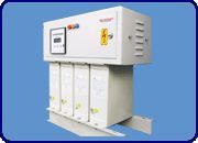
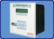
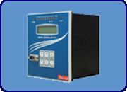
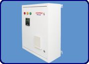
GB Controls And Services is known as top Manufacturer, Exporter, Supplier and Service Provider of best Light Fitting, Process Control Systems & Equipment, Relays, Switchgear Panels and Testing Equipments.
By clicking Send Inquiry, I accept the T&C and Privacy Policy.
Found Something Wrong with this Listing? Report Here.