Our Products
Our offered Product range includes Centre Hole Twin Cylinder, Lock-on Jaw-type Puller Set, Single Acting 1 Speed, Torque Wrench Pump with Digital Display and Two Speed Single And Double Acting Pump.

WHEN PRESSURE HAVE BEEN SETTED, PRESSURE GAUGE CONTROL AUTOCYCLE INSTEAD OF PRESSURE REGULATOR, LESS WEAR, LONG LIFE
-PROGRAM CONTROL AUTO-CYCLE, MORE QUICKLY
-HIGH SPEED AND EFFICIENCY, IMPROVING EFFICIENCY BY 50% OR MORE THAN MANUAL OPERATED PUMP
-AUTO-CYCLE OPERATION, COMPLETE BOLT TIGHTENING AND LOOSING JOB ONLY NEED TO PRESS THE AUTO BUTTON
-POWERFUL ELECTRIC MOTOR, BRUSHLESS, FREE MAINTENANCE, LONG LIFE
-POWERFUL RADIATOR CAN AUTO RUN WHEN OIL TEMPERATURE UP TO 35C, SUITABLE FOR CONTINUOUS OPERATION
-MANUAL OR AUTO-CYCLE MODEL CAN BE SHIFTED BY NEEDS, CONVENIENT FOR OPERATION
-RUNS UP TO 4 HYDRAULIC TORQUE WRENCHES SIMULTANEOUSLY BY MULTIPORT MANIFOLD
| Model | Reservoir
(L) |
Motor Specifications(KW) |
Power source |
Flow Rate (L/min) |
Operating pressure
(MPa) |
Size
(mm) |
Remote Control Line (Standard,m) |
Weight (kg) |
| AE8042K | 7.6 | 1.1 | 220V/50HZ | 8.0@0-6.5MPa 1.8@6.5-32MPa 0.85@32-70MPa |
70 | 375*300*410 | 6 | 25 |

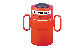
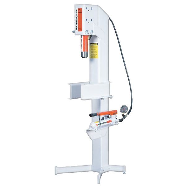
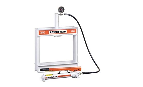
Designed for use in all positions.

IDEAL FOR PULLING AND PRESSING.
ASME B30.1 10, 000 PSI/ 700 BAR
Note: Each cylinder complete with threaded cylinder heat insert, cylinder half coupler and cylinder attaching screws.
** The RT1004 has a bypass when full stroke is reached, preventing over-pressurization of the cylinder.
| ORDER NUMBER |
CYLINDER CAPACITY (TONS) |
STROKE (MM.) |
OIL CAPACITY (CU. CM.) |
MOUNTING HOLE (MM.) |
CYLINDER EFFECTIVE AREA (SQ. CM.) |
METRIC TONSAT 700 BAR |
WEIGHT (KG) |
|
|---|---|---|---|---|---|---|---|---|
| PUSH | PUSH | RETURN | ||||||
| RT172 | 17,5 | 50,8 | 116 | – | 8,7 | 22,8 | 16,1 | 6,6 |
| RT302 | 30 | 63,5 | 258 | – | 11,9 | 40,5 | 28,5 | 12,8 |
| RT503 | 50 | 76,2 | 482 | – | 16,7 | 63,3 | 44,5 | 25,4 |
| RT1004** | 100 | 123,8 | 1.583 | 1.037 | 19,8 | 124,1 * | 87,3 | 72,6 |
| Note: Each cylinder complete with threaded cylinder heat insert, cylinder half coupler and cylinder attaching screws. ** The RT1004 has a bypass when full stroke is reached, preventing over-pressurization of the cylinder. |
||||||||

POSITIVE MECHANICAL LOCK TO SUPPORT LOAD.
| ORDER NUMBER |
CYLINDER CAPACITY (TONS.) |
STROKE (MM.) |
OIL CAPACITY (CU. CM.) |
BORE DIAMETER (MM.) |
CYLINDER EFFECTIVE AREA (SQ. CM.) |
METRIC TONS AT 700 BAR |
WEIGHT (KG.) |
|---|---|---|---|---|---|---|---|
| R552L | 55 | 50,8 | 362 | 95,3 | 71,2 | 50,1 | 15,3 |
| R556L | 55 | 152,4 | 1.087 | 95,3 | 71,2 | 50,1 | 26,3 |
| R5510L | 55 | 254,0 | 1.811 | 95,3 | 71,2 | 50,1 | 36,3 |
| R1002L | 100 | 50,8 | 677 | 130,2 | 133,1 | 93,4 | 30,0 |
| R1006L | 100 | 152,4 | 2.030 | 130,2 | 133,1 | 93,4 | 46,8 |
| R10010L | 100 | 254,0 | 3.383 | 130,2 | 133,1 | 93,4 | 64,5 |
| R1502L | 150 | 50,8 | 1.007 | 158,8 | 197,9 | 139,1 | 53,0 |
| R1506L | 150 | 152,4 | 3.019 | 158,8 | 197,9 | 139,1 | 80,4 |
| R2002L | 200 | 50,8 | 1.355 | 184,2 | 266,3 | 187,2 | 83,1 |
| R2006L | 200 | 152,4 | 4.062 | 184,2 | 266,3 | 187,2 | 117,6 |
| R2802L | 280 | 50,8 | 1.861 | 215,9 | 366,0 | 257,3 | 118,5 |
| R2806L | 280 | 152,4 | 5.583 | 215,9 | 366,0 | 257,3 | 163,0 |
| R28010L | 280 | 254,0 | 9.305 | 215,9 | 366,0 | 257,3 | 208,1 |
| R3552L | 355 | 50,8 | 2.326 | 241,3 | 457,2 | 321,4 | 173.0 |
| R3556L | 355 | 152,4 | 6.975 | 241,3 | 457,2 | 321,4 | 232,5 |
| R4302L | 430 | 50,8 | 2.841 | 266.7 | 558,5 | 392,7 | 252,4 |
| R4306L | 430 | 152,4 | 9.520 | 266.7 | 558,5 | 392,7 | 329,2 |
| R43010L | 430 | 254,0 | 14.201 | 266.7 | 558,5 | 392,7 | 405,9 |
| R5652L | 565 | 50,8 | 3.710 | 304,8 | 729,5 | 512,9 | 368,2 |
| R5656L | 565 | 152,4 | 11.129 | 304,8 | 729,5 | 512,9 | 468,0 |
| R56510L | 565 | 254,0 | 18.548 | 304,8 | 729,5 | 512,9 | 568,0 |
| * Note: Supported loads not to exceed the rated capacity of the cylinders.
Not intended to support additional dynamic loads, such as those applied by moving vehicles. |
|||||||

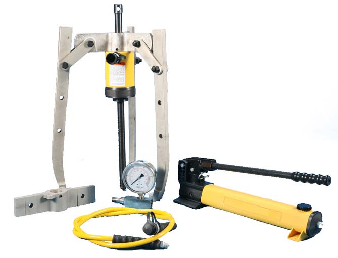
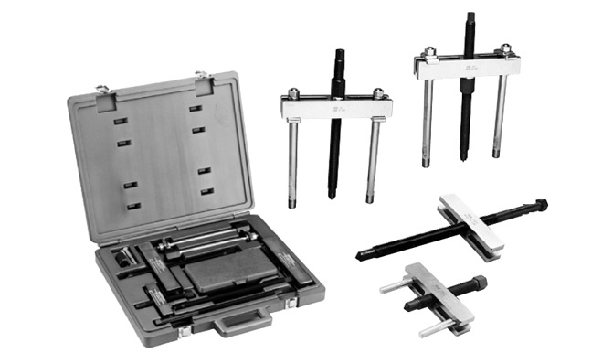
Lock-on, jaw-type puller set
Components can be assembled to create several versatile puller versions. The puller head is turned to securely lock the jaws onto the part being removed. Both a 2-way and 3-way puller head are included, plus three long-reach and three short-reach puller jaws in a plastic storage box. Easily removes gears, bearings and other press-fitted parts.
| CONTENTS ORDER NUMBER |
2-JAW | 3-JAW SPREAD | ||||||||||||
|---|---|---|---|---|---|---|---|---|---|---|---|---|---|---|
| INSIDE * | OUTSIDE | INSIDE * | OUTSIDE | |||||||||||
| MINIMUM (MM) |
MAXIMUM (MM) |
MINIMUM (MM) |
MAXIMUM (MM) |
MINIMUM (MM) |
MAXIMUM (MM) |
MINIMUM (MM) |
MAXIMUM (MM) |
|||||||
| 44195 | 38 | 114 | 19 | 127 | 38,1 | 121 | 25,4 | 114 | ||||||
| 44148 | 70 | 140 | 19 | 191 | 83 | 159 | 25,4 | 159 | ||||||
| * Can be used for internal pulling tasks when used with a slide hammer.
|
||||||||||||||

12 to 55 cu. in. (197-738 cu cm) Reservoir. Single-Speed, Single-Acting
BEST SUITED FOR APPLICATIONS WHERE THERE IS LITTLE OR NO FREE TRAVEL.
Power Team hand pumps, with the angled fill port, have a built in relief valve protection system. This system is designed to protect over-pressurization of the reservoir from sudden back pressure. This system also works as a seal to prevent oil leaks
| DER NUMBER |
FOR USE WITH | SPEED | VOLUME PER STROKE (CU. CM) |
MAXIMUM PRESSURE (BAR) |
HANDLE EFFORT (KG) |
RESERVOIR | OIL PORT (IN) |
WEIGHT (KG) |
|||
|---|---|---|---|---|---|---|---|---|---|---|---|
| LP | HP | LP | HP | OIL CAPACITY (CU. CM) |
USABLE OIL CAPACITY (CU. CM) |
||||||
| P12 | Single Acting Cylinders* |
1 | — | 1,1 | — | 700 | 34 | 197 | 148 | 3/8 NPTF | 2,6 |
| P23 | 1 | — | 2,6 | — | 210 | 32 | 390 | 333 | 3/8 NPTF | 5,5 | |
| P55 | 1 | — | 2,6 | — | 700 | 66 | 902 | 738 | 3/8 NPTF | 7,2 | |
| * Pump includes 2-Way Valve LP = Low Pressure HP = High Pressure |
|||||||||||

BEST SUITED FOR APPLICATIONS WHERE THERE IS LITTLE OR NO FREE TRAVEL.
Power Team hand pumps, with the angled fill port, have a built in relief valve protection system. This system is designed to protect over-pressurization of the reservoir from sudden back pressure. This system also works as a seal to prevent oil leaks.
| ORDER NUMBER |
FOR USE WITH | SPEED | VOLUME PER STROKE (CU. CM) |
MAXIMUM PRESSURE (BAR) |
HANDLE EFFORT (KG) |
RESERVOIR | OIL PORT (IN.) |
WEIGHT (KG) |
|||
|---|---|---|---|---|---|---|---|---|---|---|---|
| LP | HP | LP | HP | OIL CAPACITY (CU. CM) |
USABLE OIL CAPACITY (CU. CM) |
||||||
| P157 | Single-Acting Cylinders* | 2 | 10,7 | 2,6 | 97 | 700 | 64 | 2491 | 2245 | 3/8 NPTF | 11,8 |
| P159 | 2 | 42,6 | 2,6 | 22 | 700 | 64 | 2491 | 2245 | 3/8 NPTF | 11,8 | |
| P300 | 2 | 42,6 | 2,6 | 22 | 700 | 64 | 5.700 | 5081 | 3/8 NPTF | 25,1 | |
| P460 | 2 | 120,5 | 4,6 | 22 | 700 | 41 | 9.500 | 7539 | 3/8 NPTF | 24,9 | |
| P157D | Double-Acting Cylinders** | 2 | 10,7 | 2,6 | 97 | 700 | 64 | 2491 | 2245 | 3/8 NPTF | 13,1 |
| P159D | 2 | 42,6 | 2,6 | 22 | 700 | 64 | 2491 | 2245 | 3/8 NPTF | 12,7 | |
| P300D | 2 | 42,6 | 2,6 | 22 | 700 | 64 | 5.700 | 5081 | 3/8 NPTF | 25,9 | |
| P460D | 2 | 120,5 | 4,6 | 22 | 700 | 41 | 9.500 | 7539 | 3/8 NPTF | 26,3 | |
| * Pump includes 2-Way Valve ** Pump includes 4-Way Valve LP = Low Pressure HP = High Pressure |
|||||||||||
")
addedasetofcontrolsystem(importfromGermany)
KLW4100SeriesAutomaticElectricalPump
sharedasamedesignwithKLW4000seriesstandardElectricalPump,
itjustwasaddedasetofcontrolsystem(importfromGermany)onthebasicofKLW4000standardPump,
itinheritedallthecharacteristicsofKLW4000, someothercharacteristicsofthisPumpareasbelow:-SimpleOperation:OperatewithoneButton, theoperatorjustpresseddownthebuttononcetimetoachievethetaskoftighteningandloosing.
HighEfficiency:ComparewiththegeneralPump, KLW4100AutomaticPumphascompactoperationprocesstoreducesomeneedlessactionandincreaseapproximate50%ofworkingefficiency.-Manual/AutomaticBesidesoftheautomaticoperation, thePumpalsohasthefunctionofmanualoperation, forsomespecialoperation, KLW4100alsocanbeworkedwell.AdditionallytheKLW4100canwork24hourswithoutstopwithradiator, WRENalsocanmakethePumpwithotherkindsofmotorsaccordingcustomersrequirement.

This device can be used by a single operator for mapping customer phase and feeder connection in 5 seconds.
Applications: Helps to balance the loads on the phases of the low voltage network
| Phase and feeder live identifier |
| USE : This device can be used by a single operator for mapping customer phase and feeder connection in 5 seconds. Applications: Helps to balance the loads on the phases of the low voltage network Simple to use: The Central Unit (CU) is connected to all the outgoing lines on a supply substation. The Line Unit (LU), connected to any points of the network (customer, connection box, ), automatically provides you with all the useful information:Local voltage measurementPhase indication L1, L2 or L3Feeder or circuit From 1 to 6 (9 or 12)Substation. (CU code.) From 1 to 8Didactic operating mode on the Central Unit |
| TECHNICAL SPECIFICATIONS : Central Unit: FC3000 UCNominal voltage (phase-neutral): 115 Vrms to 230 Vrms (200 Vrms to 400 Vrms between phases)Maximum rated voltage: 440 Vrms (between phases, and between phase and neutral)Minimum operating voltage: 200 Vrms between phasesNetwork frequency: 50 or 60HzInput plugs L1-L2-L3-Neutral: 4 mm male IP2X (at the end of the power lead)Functions: automatic and manual modes English and FrenchInputs protection: by 3 rapid fuse holders HPC (4 A) 5mm x L=20 mmOvervoltage category: 600 V Cat.IVIP: IP51 (IP67 in closed case)Dimensions: 300 x 230 x 85 mmWeight: 2, 35 kgDetection coils:Number: 6 for FC30006, 9 for FC30009, 12 for FC300012Identification: by colour coded ring(s)Loop diameter: 120 mmLine Unit: FC3000 ULNominal voltage: 230 Vrms (between phase terminal and neutral terminal)Maximum rated voltage: 440 Vrms (between phase terminal and neutral terminal)Power supply: 4 alkaline batteries 1.5 V AAAutonomy: over 1000 detectionsInputs protection: Rapid fuse holder HPC (KTK-6 / 6 A) 10mm x L=38 mmOvervoltage category: 600 V Cat.IVIP: IP54Approximate dimensions: 250 (235) x 130 x 65 mmProtection: shockproof rubber-type shell caseWeight: 1.4 kg with shell case, lead, test probes and alligator clipsComplete unitSynthetic carry and storage case, IP67 when closedOperating temperature: from 0C to +40C / Hygrometry < 90% non condensingStorage and transport temperature: from -20 to +70C |
| ADVANTAGES : Safety of the operator and the installations guaranteed:Category IV device protected by HRC fusesInsulated connection accessoriesReliable;Feeder identification signal secured by drawn current signalInformation re circulated on the network by PLCBuilt-in self-testSealed LU protected against outside risksA robust, complete set designed for field use:Central Unit in a heavy duty sealed case, also used to store and carry the Line Unit as well as all the accessoriesLine Unit protected by a shockproof shell made of a soft material |

Identify or trace the HV or LV phases at any point of the electrical distribution networks (substations, lines, LV networks, etc.)
| Phase Identifier with Unlimited range BT-HT |
| USE : The FC4000 makes it possible to identify or trace the HV or LV phases at any point of the electrical distribution networks (substations, lines, LV networks, etc.) from a central reference.The network remains in its normal operating scheme and energized.The FC4000 can prepare accurately and in real time all operations requiring perfect knowledge of the phases:Preparation worksetting up recharge, setting service processors. |
| CHARACTERISTICS : The reference unitPlaced permanently in a position, it is accessible by conventional telephone CPR.It includes:A tag containing the antenna and GPS receiver for accurate timing measurements.A housing containing the measurement and communication electronics.On the back side is all the connections. This housing can be attached to a relay board or integrated into a 19 4U rack.On the front panel are all function, power, GPS synchronization indicators, presence of reference voltage 1 and 2 and telephone line socket.The mobile unit:It consists of a bag repeater containing all communication and measuring elements.The GPS mobile tag (precise synchronization of measurements).The mobile phone (communication with the reference). Intelligent SensorOnce on, all the functions are automatic and without interpretation.It displays the phase index.It automatically recognizes the following situations:direct voltage phase / earth of the LV network, the resulting tensions capacitive dividers HTA cells.The signals coming from the sensor for the bare networks HT. Usable on open stations and aerial HTA networks, it is autonomous and works only on contact. Reference Unit:voltage references from 50 to 250 Vrms. Power consumption to 1 500 measurements. Sensor for bare MV networks:operating voltages phase / earth 2.5 to 30 kV.infrared communication distance max. 20 m, beam diameter at 6 m: 1 m; Contact measurement.Automatic start-up by presence of voltage.automatic cut-off when the voltage is removed.internal power supply by battery 9V autonomy> to 1 500 measurements.fixation by standard notched tip. |
| MORE PRODUCT: Profit for the phase identification with a central reference:better planning of distribution networks and better economic management of their developments.Reduction or postponement of investments (eg HV / LV transformers overloaded prematurely due to poor distribution of single-phase loads).A reduction in the operating and intervention costs: planned and knowingly implemented intervention, for example additional work durations caused by the lack of prior knowledge of existing indices in an installation.Reduction of customer recharge times (connection of generators).Better security of goods and people.Compliance and installation of visual markings on electrical installations. |