New to ExportersIndia? Join Now
My ExportersIndia
For Buyer
For Seller
For Help
Our Products
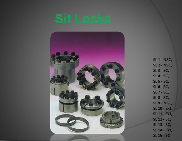
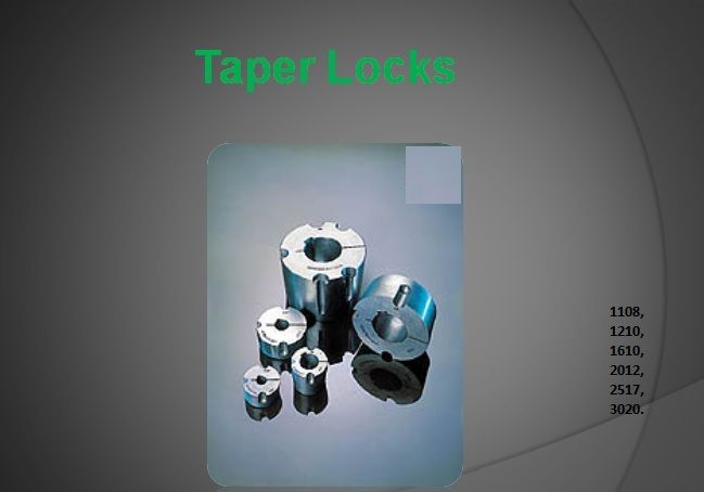
We are leaders in the market for providing best range of Taper Locks and Sit Locks
By clicking Send Inquiry, I accept the T&C and Privacy Policy.
Found Something Wrong with this Listing? Report Here.