Our Products
Our Complete range of products are Ultrasonic Flow Meter, Electromagnetic Flow Meter, Vortex Flow Meter, OVAL-GEAR FLOW METER and Turbine Flow Meter.
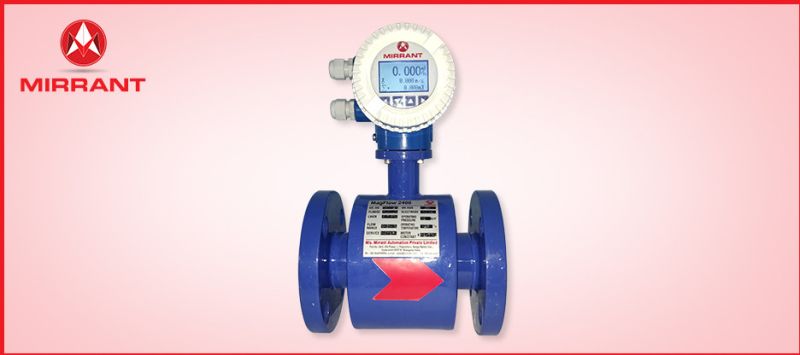
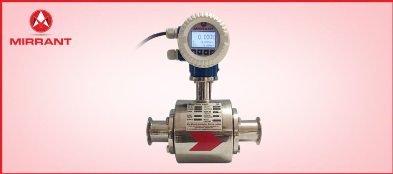
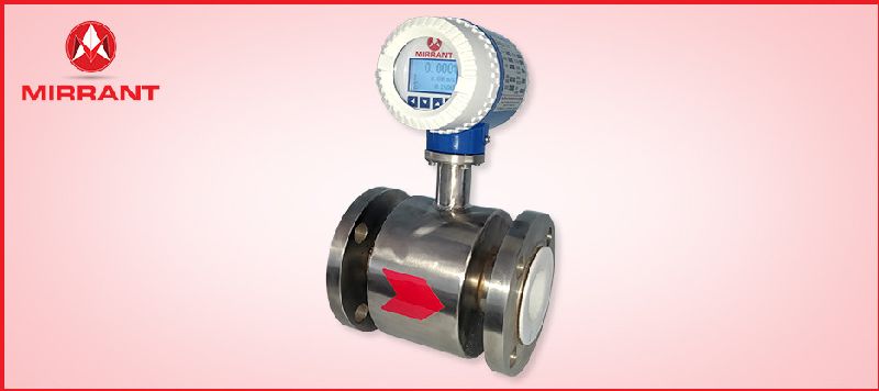
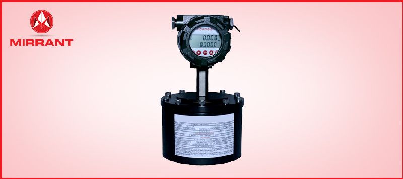
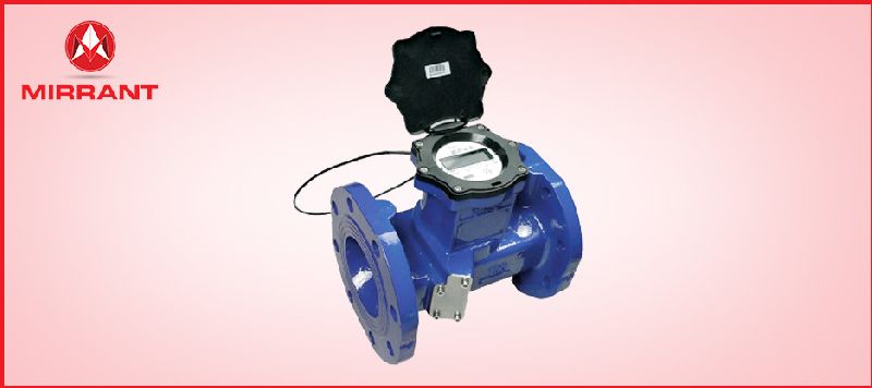
The working principle of a magnetic flow meter is based on Faraday’s law of electromagnetic induction.
According to Faraday’s law, when the conductive fluid flows through a magnetic field of the sensor, an electromotive force proportional to the volume flow is generated between the pair of electrodes, which is perpendicular to the flow direction and the magnetic field.
The amplitude of the electromotive force can be expressed as
E = kBDv
Where E:Induced electric potential,
K: constant,
B:Magnetic flux density,
D:The inner diameter of the measuring Tube,
V:The average velocity of the fluid in the axial direction of the electrode cross-section inside the measuring tube.
Additional Information:
Delivery Time : 1Week
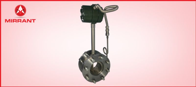
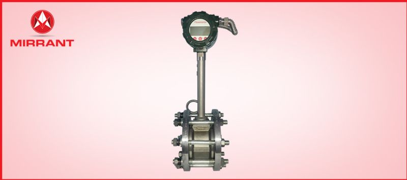
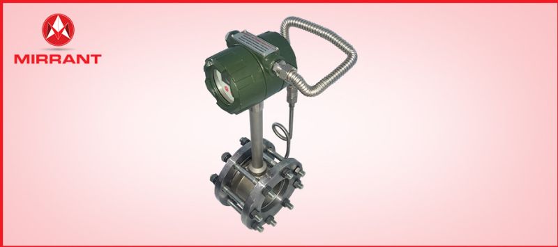
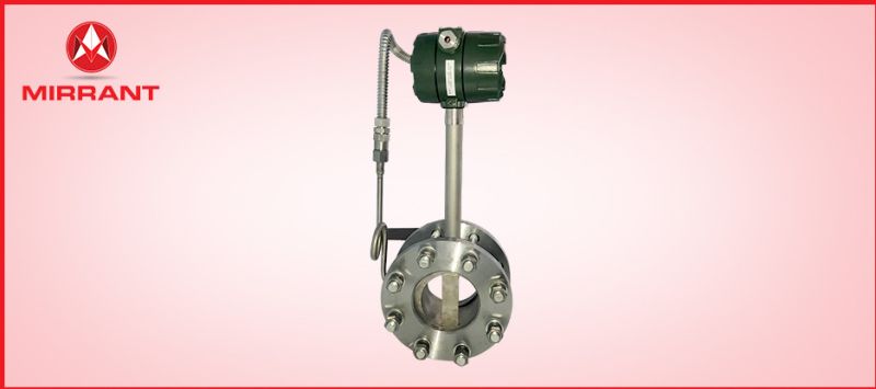
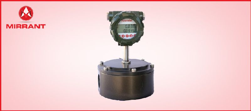
The measuring principle is based on the Karman vortex street. The measuring tube contains a bluff body at which vortex shedding occurs and which is detected by a sensor unit located behind. The frequency f of the vortex shedding is proportional to the flow velocity v. The nondimensional Southall number S describes the relationship between vortex frequency f, width d of the bluff body and the average flow velocity v:f=SV/d
The vortex frequency is recorded at the flow sensor and evaluated at the signal converter. Vortex flowmeters are used to measure the flow of gases, vapours and liquids at completely
1.Measurement of saturated steam and superheated steam
2.Steam boiler monitoring
3.Heat metering of steam and hot water
4.Wide range of applications, gas, liquid, steam flow can be measured
5.Measurement of consumption in compressed air systems
6.Industrial Gases i.e. Air, Oxygen, Nitrogen, Coal Gas, Natural gas. etc.
7.Industrial Liquids i.e. Water, Oil, Food liquid, Chemicals etc.
Additional Information:
Delivery Time : 1Week
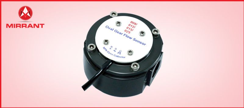
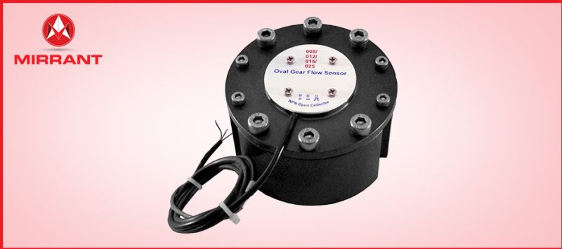
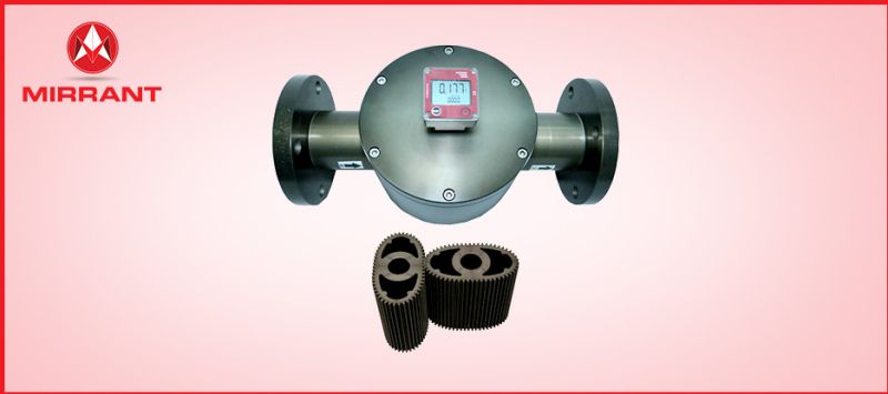
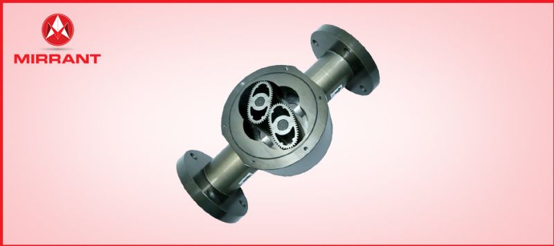
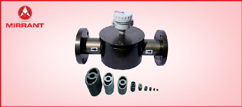
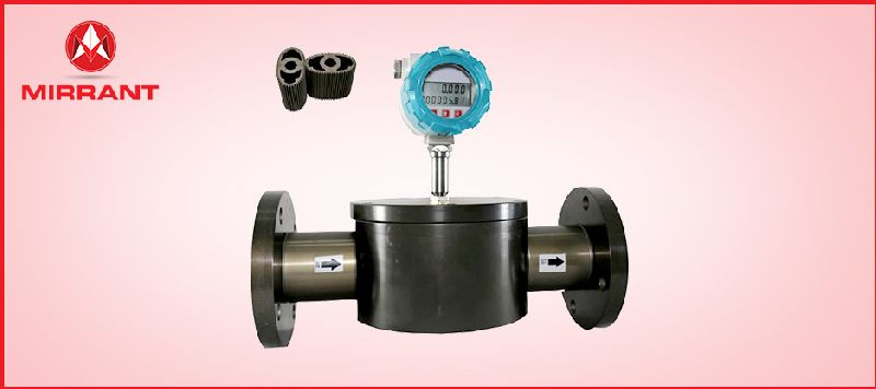
Oval gear meters are displacement-type volume meters that transport defined incremental volumes in individual measuring chambers. The measuring element consists of two high precision toothed oval gears, which are driven by the flow of the medium and mesh with each other. In this way, a defined volume is transported for each rotation of the pair of oval gears. The number of rotations is a measure of the amount of fluid that has passed through the meter. The rotations are detected by a sensor element. A very precisely adjusted gear pair within the casing forms the measuring element. The in flowing medium causes the gear pair to rotate. The rotary motion is scanned by contactless sensors. Since each individual tooth generates a pulse, this results in a very high resolution. Consequently, even the smallest volumes can be measured or dosed precisely. The measurement unit contains two pick-offs that are circumferentially offset by of a tooth pitch to generate a 2 channel flow-proportional frequency signal. Suitable processing of the signal provides an greater resolution and the option to identify the flow direction. Basically, the measurement accuracy increases with increase in viscosity of the media. The oval gear flow meter comprises oval-shaped, geared rotors which rotate within a housing of specified geometry. Fluid differential pressure causes the intermeshing gears to rotate, trapping a ‘pocket’ of fluid between the gear and the outer housing and subsequently emptying the fluid pocket into the downstream flow
Additional Information:
Delivery Time : 1Week
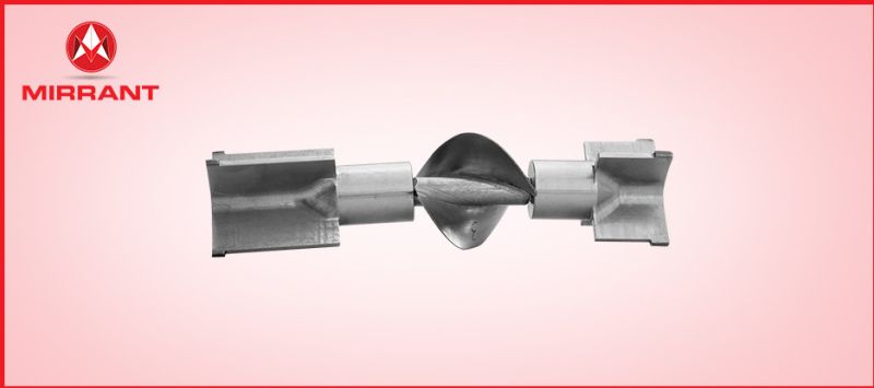
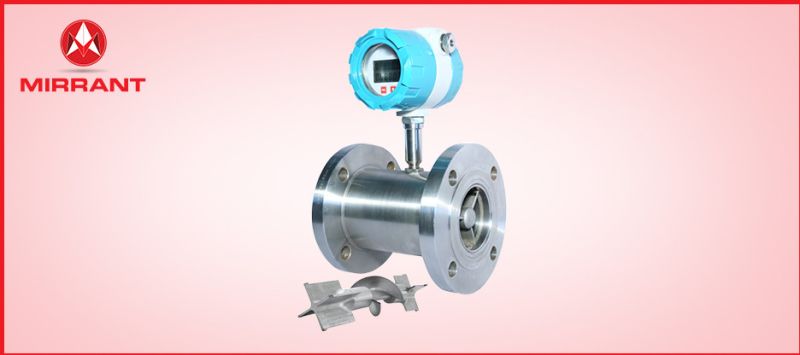
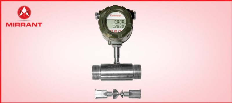
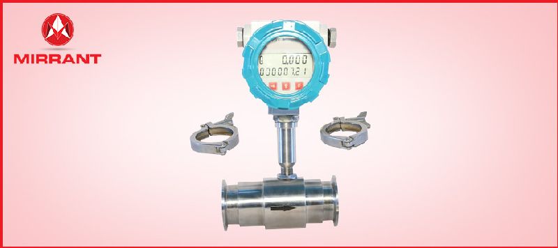
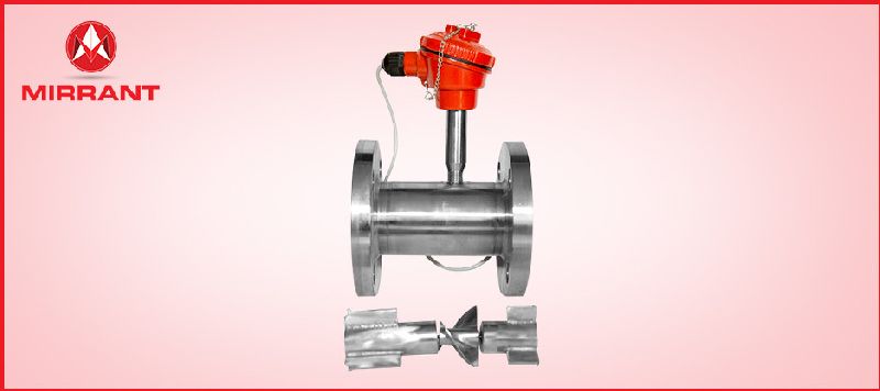
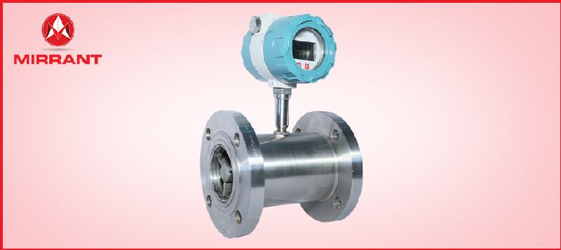
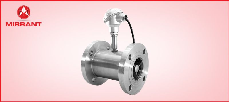
Turbine Flow Meter is a volumetric measuring turbine type. The flowing fluid engages the rotor causing it to rotate at an angular velocity proportional to the fluid flow rate. The angular velocity of the rotor results in the generation of an electrical signal (AC sine wave type) in the pickup. The summation of the pulsing electrical signal is related directly to total flow. The frequency of the signal relates directly to flow rate. The vaned rotor is the only moving part of the flow meter. The Turbine flow meter (axial turbine) was invented by Reinhard Woltman and is an accurate and reliable flow meter for liquids and gases. It consists of a flow tube with end connections and a magnetic multi bladed free spinning rotor (impeller) mounted inside; in line with the flow. The rotor is supported by a shaft that rests on internally mounted supports.
The Supports in Process Automatics Turbine Flow Meters are designed to also act as flow straighteners, stabilizing the flow and minimizing negative effects of turbulence. The Supports also house the unique open bearings; allowing for the measured media to lubricate the bushes – prolonging the flow meters life span. The Supports are fastened by locking rings (circlips) on each end.
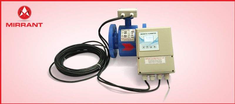
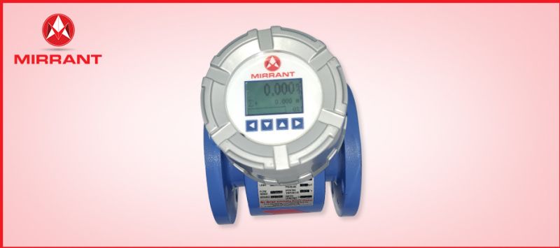
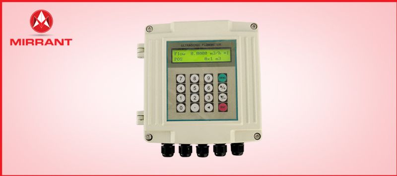
Display
Display1:Battery Powered, Local Display Display2:Battery Powered, Local Display and Pulse Output Display3:External 24VDC Powered, Local Display and Pulse Output External 24VDC Powered, Local Display and 4-20mA Output External 24VDC Powered, Local Display, 4-20mA Output and RS485 Communication Display4:External 230VAC Powered, Remote Display, Pulse Output, 4-20mA Output Relay, RS485 Modbus Communication and Data log
Additional Information:
Delivery Time : 1Week
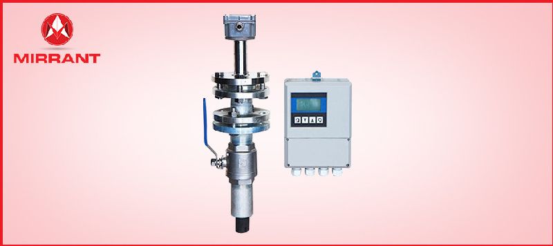
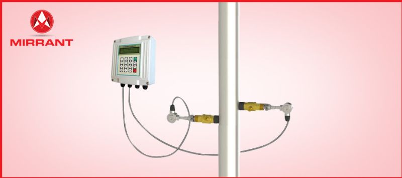
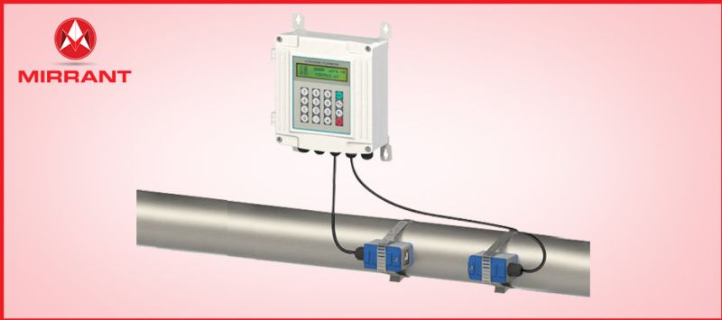
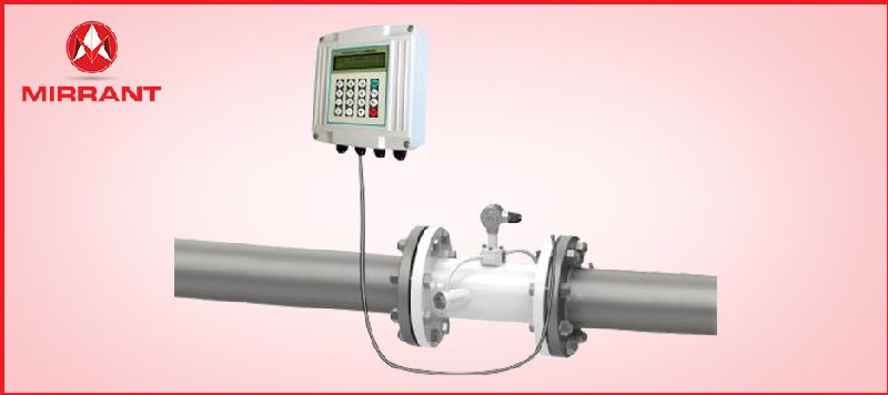
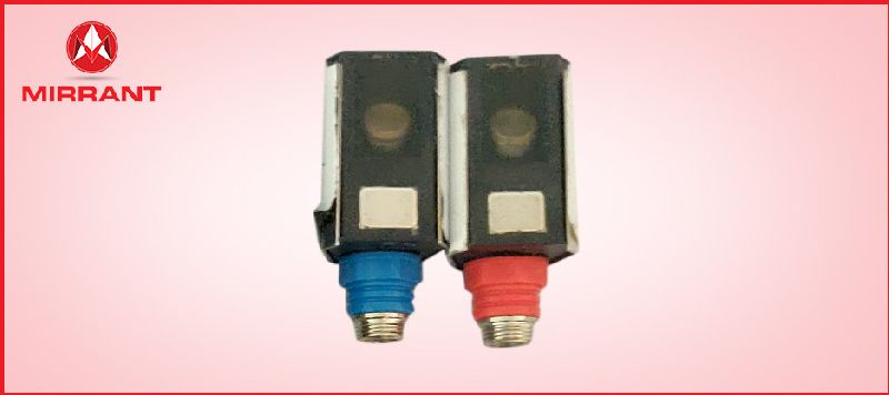
The working principle of a Ultrasonic flow meter is based on the transit-time Technology.The ultrasonic flow meter utilizes two ultrasonic transducers that function as both ultrasonictransmitter and receiver. The ultrasonic flow meter operates by alternately transmitting and receiving a burst of ultrasound between the two transducers by measuring the transit time that it takes for sound to travel between the two transducers in both directions. The difference in the transit time t measured is directly proportional to the velocity ( V) of the liquid in the pipe. With no flow, the transit time will be equal in both directions. With flow ultrasound will travel faster in direction of flow &slower against the flow. The liquid velocity (V) inside the pipe can be related to the difference in time of flight through the following equation
\nV = K x Dx t
\nWhere V: Velocity of the Liquid
\nK: Constant
\nD: Distance between the two transducers
\nt: Difference in transmit time
Additional Information:
Delivery Time : 1Week