New to ExportersIndia? Join Now
My ExportersIndia
For Buyer
For Seller
For Help
Others (14)
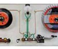
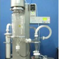
We Sci-tech Engineering Corporation are a leading and distinguished Manufacturer, Exporter, Supplier and Retailer of quality Automotive Brakes and Dryers.
By clicking Send Inquiry, I accept the T&C and Privacy Policy.
Found Something Wrong with this Listing? Report Here.