Listing ID #4069524
Company Information
Ask for more detail from the seller
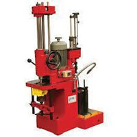
Contact Supplier| Product Name | Horizontal Boring Machines |
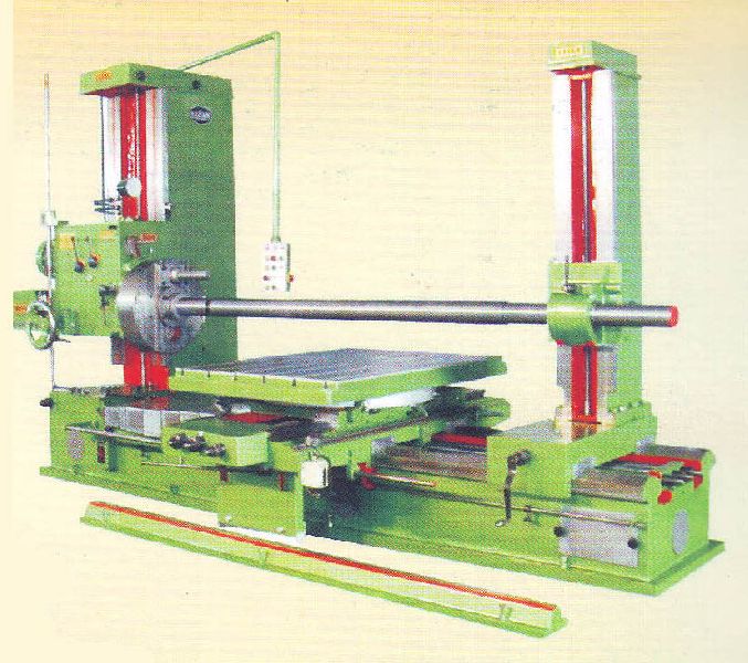
GURU NANAK Engineering Works(Regd.) with over 4 Decades' experience, have earned an enviable reputation as manufacturer of High Quality, Reliable & economical "KARAM" Highly Precision Horizontal Boring Machine which is a versatile Machine Tool for all types of roughing & finishing operations within the range of BORING, MILLING, DRILLING, REAMING & FACING. It is most suitable for machining bores in various types of Machine Bodies & Gear Boxes, for surface milling & especially for large dia flange facing. High precision workmanship, Sturdy & well proportionate design of Castings, High powered spindle & face plate drive along with Wide Range of Spindle Speeds & Gear Box Feeds ensure high production of accurately machined parts with the use of both H.S. Steel & Carbide tools. The Robust & Massive construction of the machine is a guarantee to withstand fully all the working stresses.
* The Casting is done with the mixture of 25% Steel & Ferro Chrome etc. to acquire proper Brinell Hardness & it is also seasoned for at least six months. The Machine is manufactured to Grade-1 Limits of ACCURACY.
* High Accuracy of machining due to precision scrapped/ground Guideways of Bed & Pillars etc.
* Fine Positioning by Dial Indicatiors & Verniers or Digital Read-Out System having an accuracy of .005 mm resolution for close manufacturing tolerances.
* Geometrical Accuracy of the machine conforms to Dr. SCHLESINGER'S ACCEPTANCE TEST CHART.
* Heavily ribbed box type Bed to withstand the Heavy Loads & Sturdy box type Columns to resist the heavy cutting force even at elevated height.
* Precise Synchronized Vertical Travel of Head Stock & Boring Stay Support.
* All traverses of X,Y & Z Axis of the machine as well as circular movement of the Work Table are
provided with automatic Feeds and Rapid Travels.
* All gears are precision cut on imported Mother Machinery to ensure smooth and Silent running.
* Manual Boring Head Height setting adjustment with a lever attached to feed gear box.
* Centralized control with swiveling Pendent Board for easy and convenient operations.
* Hand Operated knurled Knob attached to head stock drive motor and hand operated wheel attached to feed gear box motor for the safest engagement of speeds and feeds respectively.
* Special Attachments like Threading, Milling and Taper Boring Attachments permit to perform Multi-
Operations on a single machine.
* 4x90° Position of Rotary Table set with the help of an accurate adjustable stopper.
SAFETY CLUTCHES: To Disengage: ( a) Facing Mechanism (b) Sliding Mechanism of Cross Slide
(c) Rotary Movement of Work Table ( d) Longitudinal Movement of Work Spindle.
Apart from above safety Measures, Limit Switches & suitable Shear Pins are also provided for total safety of the machine
| MM | MM | MM | MM | MM | MM |
| 1. Alloy Steel Work Spindle Handened & Ground-Diameter | 65 | 80 | 100 | 110 | 125 | 150 |
| 2. Morse Taper Number | 4 | 5 | 6 | 6 | 6 | Metric 80 |
| 3. Max. Longitudinal Movement of Working Spindle | 410 | 510 | 510 | 510 | 600 | 800 |
| 4. Number of Spindle Speeds | 9 | 9 | 9 | 9 | 9 | 9 |
| 5. Range of Spindle Speeds - R.P.M. | 20 to 300 | 15 to 300 | 15 to 300 | 15 to 250 | 15 to 250 | 15 to 250 |
|
6. Longitudinal Work Spindle Feeds (Nos.) |
9 | 9 | 9 | 9 | 9 | 9 |
| 7. Max. Height of the Spindle Axis from Table Surface |
800 | 925 | 1000 | 1100 | 1250 | 1500 |
| 8. Min. Height of the Spindle Axis from Table Surface |
20 | 25 | 35 | 35 | 35 | 50 |
| 9. Dimensions of the Rotary Table | 880x1050 | 900x1125 | 1030x1375 | 1100x1450 | 1225x1675 | 1500x2000 |
| 10. Longitudinal Table Traverse | 1500 | 1625 | 1775 | 1925 | 2050 | 2225 |
| 11. Long. Table Traverse Feeds ( Including one Rapid) |
10 | 10 | 10 | 10 | 15 | 15 |
| 12. Transversal Table Travel Feeds (Including one Rapid) |
10 | 10 | 10 | 10 | 15 | 15 |
| 13. Vertical Head Stock Travel Feeds (Including one Rapid) |
4 | 4 | 4 | 4 | 15 | 15 |
| 14. Rotary Table Autiomatic Feeds ( Including one Rapid) |
10 | 10 | 10 | 10 | 15 | 15 |
| 15. Max. Cross Movement of the Table | 910 | 1000 | 1100 | 1300 | 1550 | 2000 |
| 16. Max. Distance Between Stay Bearing and Facing Head |
2150 | 2400 | 2690 | 2800 | 2950 | 3400 |
| 17. Facing Head Diameter | 450 | 505 | 555 | 600 | 650 | 700 |
| 18. Weight Approximate in Kgs. | 7500 | 8500 | 10000 | 11500 | 16500 | 20000 |

Connect with us