Our Products
We offer a complete product range of Ultra High Power Alluminium Resistors, Coiled Wire Resistors, Edge Wound Resistors, High Power Aluminium Resistors and Double Coil Resistor with Enclosure

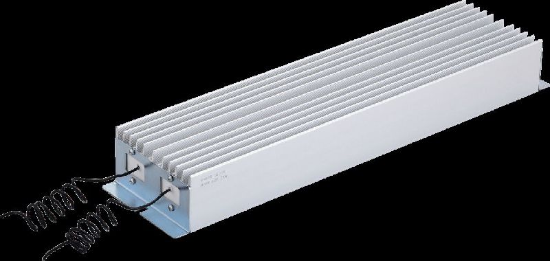
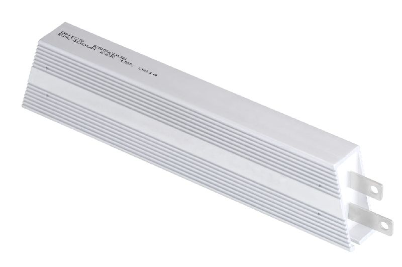
Onics UHPAR series resistor are capable of withstanding very high pulse loads, at the same time they get cooled faster compared to conventional resistors and are best suitable for wind turbines and other braking applications. These resistors are available in eleven different power ratings. These resistors are continuously rated.
Features :
Ordering Process
For Example :
Note :
Graph
Resistor Dimensions (IN Mm)
| Cat No. | Power | L | L1 | Approx Weight (KGS) |
|---|---|---|---|---|
| UHPAR500 | 500W | 180 | 60 | 4 |
| UHPAR750 | 750W | 210 | 110 | 4.8 |
| UHPAR1000 | 1000W | 360 | 260 | 5.6 |
| UHPAR1250 | 1250W | 330 | 230 | 6.9 |
| UHPAR1450 | 1450W | 400 | 300 | 8.2 |
| UHPAR1725 | 1725W | 460 | 360 | 9.2 |
| UHPAR2200 | 2200W | 560 | 460 | 11 |
| UHPAR2800 | 2800W | 660 | 560 | 12.8 |
| UHPAR3000 | 3000W | 760 | 660 | 14.6 |
| UHPAR3300 | 3300W | 860 | 760 | 16.5 |
| UHPAR3500 | 3500W | 960 | 860 | 18.5 |
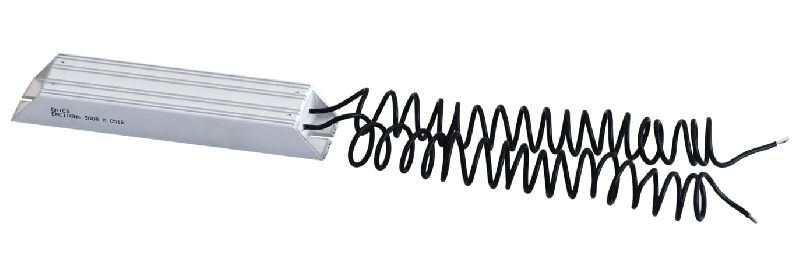
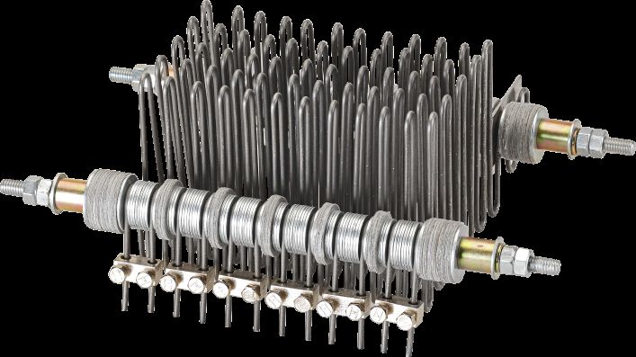
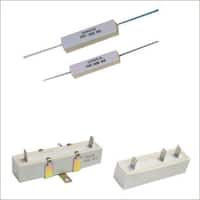
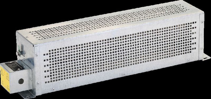
These resistors are constructed by coiling wire and supported by ceramic insulatorson a steel strip. The resistive element is of stainless steel, fecral or Nickel Chromium. The standard end terminal is welded or screwed firmly to the resistive element, which provides good electrical connections to the resistive elements.
Features :
Application : These Resistors are used in conjuction with appropriate control equipment to accelerate, dynamic braking of motors. These resistors are also ideally suited for use in the secondary of AC wound rotor motors for accelerating speed regulating services. These resistors are also used as neutral grounding resistors. AC and DC dynamic braking load banks, current limiting and blast for mercury vapor lamp.
Material Specifications :
Graph
Type OCRE From 1 KW TO 60 KW
OCR Dimensions IN Mm
| Power (KW) | A | B | C | D |
|---|---|---|---|---|
| 500w | 295 | 90 | 60 | 265 |
| 600w | 370 | 90 | 60 | 340 |
| 800w | 445 | 90 | 60 | 415 |
| 1000w | 520 | 90 | 60 | 490 |
OCRE Dimensions IN Mm
| Power (KW) | A | B | C | D | E | F |
|---|---|---|---|---|---|---|
| 1KW TO 3KW | 380 | 650 | 180 | 330 | 555 | 215 |
| 4KW TO 6KW | 380 | 650 | 295 | 330 | 555 | 215 |
| 7KW TO 9KW | 380 | 650 | 410 | 330 | 555 | 215 |
| 10KW TO 12KW | 380 | 650 | 525 | 330 | 555 | 215 |

Features :
Application : These Resistors are used in conjuction with appropriate control equipment to accelerate, dynamic braking of motors. These resistors are also ideally suited for use in the secondary of AC wound rotor motors for accelerating speed regulating services. These resistors are also used as neutral grounding resistors. AC and DC dynamic braking load banks, current limiting and blast for mercury vapor lamp.
Graph
Dimensions (IN Mm)
| Power (KW) | A | B | C | D |
|---|---|---|---|---|
| 500W | 223 | 78 | 45 – 52 | 190 |
| 750W | 298 | 78 | 45 – 52 | 265 |
| 1000W | 373 | 78 | 45 - 52 | 340 |
| 1250W | 448 | 78 | 45 - 52 | 415 |
| 1500W | 523 | 78 | 45 - 52 | 490 |
Features :
Ordering Process
For Example :
Note :
Graph
Dimensions (IN Mm)
| Model | Nominal Power @40 Degree C | A | B | C | D | E | F |
|---|---|---|---|---|---|---|---|
| HPAR1KW | 400w | 235 | 223 | 203 | 235 | 115 | 60 |
| HPAR1.2KW | 500w | 285 | 273 | 253 | 285 | 115 | 60 |
| HPAR1.5KW | 570w | 335 | 323 | 303 | 335 | 115 | 60 |
| HPAR2KW | 650w | 385 | 373 | 353 | 385 | 115 | 60 |
| HPAR2.5KW | 750w | 485 | 473 | 453 | 485 | 115 | 60 |
| HPAR3KW | 830w | 585 | 573 | 553 | 585 | 115 | 60 |
| HPAR3.5KW | 920w | 635 | 623 | 603 | 635 | 115 | 60 |
| HPAR4KW | 1000w | 685 | 673 | 653 | 685 | 115 | 60 |
| HPAR4.5KW | 1100w | 735 | 723 | 703 | 735 | 115 | 60 |

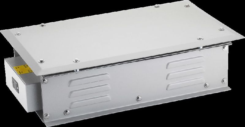
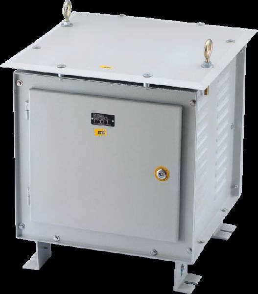
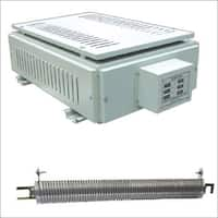
Onics DCR series resistor are capable of with standing high pulse loads, at the same time they get cooled faster compared to conventional resistors and are best suitable for dynamic braking. These resistors are available in five different power ratings. DCRE resistors are also available with standard enclosure upto 4500W, where multiple resistor are connected in series or paralled.
ConstructionDCR series resistor are manufactured by winding resistance wire coil of different resistive material on ceramic part supported by metal strip, ends of resistance wire are screwed firmly to end clamps These resistor are available individually or assembled in enclosure. Enclosures are yellow or white zinc or galvanized.
Features :
Graph 01
Graph 02
Graph 03
Resistor Dimensions (IN Mm)
| Cat No. | Power | A | B | C | D | H | Approx Weight (KGS) |
|---|---|---|---|---|---|---|---|
| DCRE500 | 500w | 290 | 260 | 125 | 100 | 150 | 2.2 |
| DCRE750 | 750w | 365 | 335 | 125 | 100 | 150 | 2.65 |
| DCRE1000 | 1000w | 440 | 410 | 125 | 100 | 150 | 3.4 |
| DCRE250 | 1250w | 515 | 485 | 125 | 100 | 150 | 3.9 |
| DCRE500 | 1500w | 590 | 560 | 125 | 100 | 150 | 4.3 |
| DCRE2000 | 2000w | 440 | 410 | 210 | 160 | 150 | 5.2 |
| DCRE2500 | 2500w | 515 | 485 | 210 | 160 | 150 | 6.25 |
| DCRE3000 | 3000w | 590 | 560 | 210 | 160 | 150 | 7.45 |
| DCRE3750 | 3750w | 515 | 485 | 300 | 250 | 150 | 9.4 |
| DCRE4000 | 4000w | 440 | 410 | 300 | 250 | 150 | 10 |
| DCRE4500 | 4500w | 590 | 560 | 300 | 250 | 150 | 11.45 |
| DCRE5000 | 5000w | 515 | 485 | 380 | 330 | 150 | 12.3 |
| DCRE6000 | 6000w | 590 | 560 | 380 | 330 | 150 | 13.15 |
Technical Details
| Type/Watt | A (mm) | B (mm) | C (mm) | D (mm) | Approx. Weight (g) |
|---|---|---|---|---|---|
| DCR500W | 225 | 90 | 65 | 195 | 875 |
| DCR750W | 300 | 90 | 65 | 270 | 1200 |
| DCR1000W | 370 | 90 | 65 | 340 | 1600 |
| DCR1250W | 445 | 90 | 65 | 415 | 1900 |
| DCR1500W | 520 | 90 | 65 | 490 | 2250 |
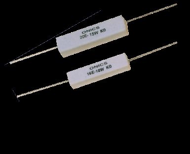
features
low price small size.high power and excellent load life stabilityexcellent short time over loadstrongly resistant to moisture & solvent.self-extinguish material is used in encapsulation.non-inductive type available.high-surge-resistant items are available.wire terminals available. Standard length 300mm longer length upto 1.25 mtrs.(optional) can also be supplied.models with thermal switch available.custom built resistors is our speciality.
technical parameters
1. Operating temp. - -55°c - +275°c2. Insulation resistance - >20m min3. Dielectric strength - ac1500v, 3500v, 5000v for 1 min4. Temp. Coefficient - 50 ppm/°c, 100 ppm/°c, 260 ppm/°c5. Short time over load - 10 x wattage rating, 5 sec6. Moisture resistance - temp 40°c moisture 95% dc100v500h7. Thermal shock - wattage rating 30min. -25°c, 15min8. Vibration - 10c/c 50 c/s 10 c/s (1min) -2h each of paralleled and right angle.9. Load life - wattage rating 1.5 h on, 30min off, 1000h10. Derate to zero - at 275°c
note:if finned heatsink is used, surface area should be equal to the above heat sink area.
Additional Information:
Payment Terms : L/C, D/P, T/T
Packaging Details : As per customer requirement.
Delivery Time : 7 to 15 days

Features :
Applications :
Additional Information:
Payment Terms : L/C, D/P, T/T
Packaging Details : As per Customer requirement.
Delivery Time : 7 TO 10 DAYS
Graph
Derating Curve
SLR Series
| Cat. No. | Watt @20°c | 1 Sec .Watt | 10 Sec.Watt | 40 Sec. Watt | Resistance range (ohm) | L (mm) | L1 (mm) | Weight (gm) |
|---|---|---|---|---|---|---|---|---|
| SLR 100 | 100 | 2500 | 700 | 250 | 10 W-500W | 110 | 98 | 240 |
| SLR 150 | 125 | 4700 | 1200 | 425 | 10 W-500W | 166 | 154 | 375 |
| SLR 200 | 150 | 6500 | 1600 | 550 | 10 W-500W | 216 | 204 | 525 |
| SLR 250 | 200 | 8000 | 2200 | 750 | 10 W-500W | 270 | 258 | 650 |
| SLR 300 | 250 | 10000 | 2500 | 900 | 10 W-500W | 320 | 308 | 810 |
| SLR 400 | 300 | 14000 | 4300 | 1100 | 10 W-500W | 420 | 408 | 1070 |
| SLR 500 | 400 | 17000 | 5000 | 1400 | 10 W-500W | 520 | 508 | 1250 |
The Above details have been calculated for a duty cycle of 120 sec. without using heatsink at surface temp. of 275°C
Material Specifications :
Graph
Dimensions In Mm
| Power (KW) | A | B | C | D | E |
|---|---|---|---|---|---|
| 9KW TO 11KW | 725 | 610 | 525 | 403 | 650 |
| 12KW TO 24KW | 725 | 610 | 725 | 403 | 650 |
| 25KW TO 36KW | 725 | 610 | 925 | 403 | 650 |
| 37KW TO 50KW | 725 | 610 | 1125 | 403 | 650 |
| 51KW TO 60KW | 725 | 610 | 1325 | 403 | 650 |
| 61KW TO 72KW | 72 | 610 | 1525 | 403 | 650 |
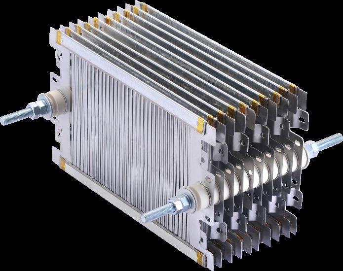
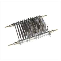
Construction : These type of resistors use sheets of Nichrome or Fecral or Stainless Steel as resistive material. These sheets are punched to required Ohmic values and then assembled on tie rod with ceramic support and insulation as module. Such multiple modules are assembled in an enclosure to achieve required power.
Applications :
Material Specifications :
Graph
Dimensions (IN Mm)
| Power (KW) | A | B | C | D | E |
|---|---|---|---|---|---|
| 5KW | 375 | 550 | 325 | 325 | 450 |
| 7.5KW | 475 | 550 | 325 | 425 | 450 |
| 10KW | 550 | 550 | 325 | 500 | 450 |
| 12.5KW | 650 | 550 | 325 | 600 | 450 |
| 15KW | 725 | 575 | 450 | 675 | 475 |
| 17.5KW | 800 | 575 | 450 | 750 | 475 |
| 20KW | 900 | 575 | 450 | 850 | 475 |
| 22.5KW | 1000 | 575 | 450 | 950 | 475 |
| 25KW | 1050 | 575 | 450 | 1000 | 475 |
| 30KW | 725 | 575 | 700 | 675 | 475 |
| 40KW | 900 | 575 | 700 | 850 | 475 |
| 50KW | 1050 | 575 | 700 | 1000 | 475 |
| 60KW | 900 | 575 | 950 | 850 | 475 |


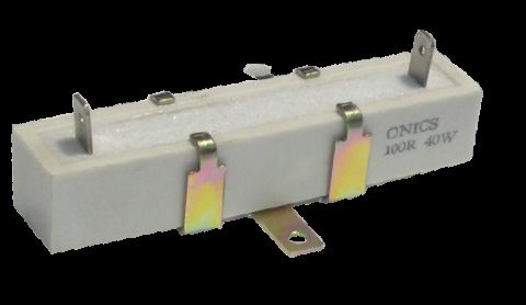
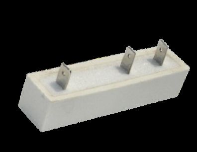
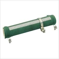
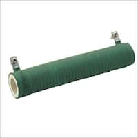
In this type resistor is wound with Copper Nickel or Nickel Chromium wire on ceramic tube and then coated with high temperature non-flammable silicone coating. These resistors are suitable as loading resistors, braking resistor, capacitor discharge & many more application.
Features :
Note : Mounting hardware Optional. Add M if mounting hardware requires. eg. SVRV-M, SVRF-M
Graph 01
Graph 02
Technical Details
| Watts | Resistance Range | Dimensions (MM) | |||||
| Fixed Type | Adjustable Type | L | W | D | L1 | H | |
| 25W | 0.1 OHM – 25 K | 0.1 OHM – 3.0 K | 65 | 8 | 16 | 83 | 33 |
| 30W | 0.1 OHM – 30 K | 0.1 OHM – 3.3 K | 78 | 8 | 16 | 96 | 33 |
| 40W | 0.1 OHM – 40 K | 0.1 OHM – 4.9 K | 75 | 8 | 20 | 95 | 35 |
| 50W | 0.1 OHM – 50 K | 0.1 OHM – 6.0 K | 100 | 8 | 20 | 120 | 35 |
| 75W | 0.1 OHM – 75 K | 0.1 OHM – 9.0 K | 150 | 8 | 20 | 170 | 35 |
| 100W | 1 OHM – 100 K | 1 OHM – 12 K | 150 | 8 | 26 | 172 | 52 |
| 150W | 1 OHM – 150 K | 1 OHM – 16 K | 175 | 8 | 34 | 201 | 60 |
| 200W | 1 OHM – 200 K | 1 OHM – 24 K | 200 | 8 | 34 | 226 | 60 |
| 250W | 1 OHM – 250 K | 1 OHM – 30 K | 250 | 8 | 34 | 276 | 60 |
| 300W | 1 OHM – 300 K | 1 OHM – 50 K | 300 | 15 | 34 | 326 | 60 |
| 400w | 1 OHM – 400 K | 1 OHM – 60 K | 250 | 15 | 62 | 320 | 103 |
| 500W | 1 OHM – 500 K | 1 OHM – 80 K | 300 | 15 | 62 | 370 | 103 |
| 600W | 1 OHM – 600 K | 1 OHM – 90 K | 350 | 15 | 62 | 420 | 103 |
| 750W | 1 OHM – 700 K | 1 OHM – 100 K | 400 | 15 | 62 | 470 | 103 |
| 1000W | 1 OHM – 800 K | 1 OHM – 110 K | 500 | 15 | 62 | 570 | 103 |
| 1250W | 1 OHM – 900 K | 1 OHM – 120 K | 550 | 15 | 62 | 620 | 103 |
| 1500W | 1 OHM – 1000 K | 1 OHM – 130 K | 600 | 15 | 62 | 670 | 103 |
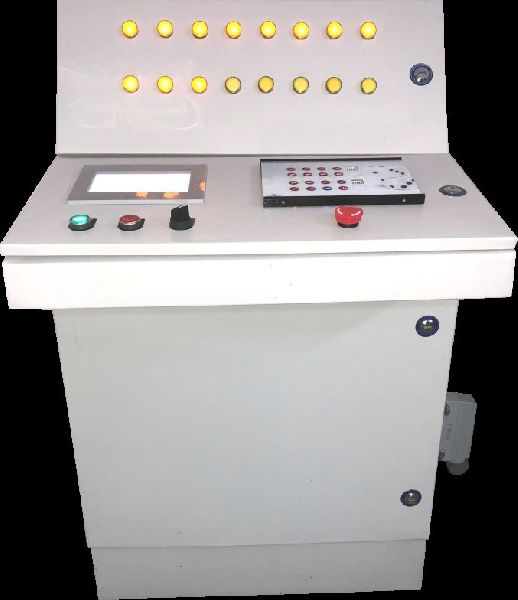
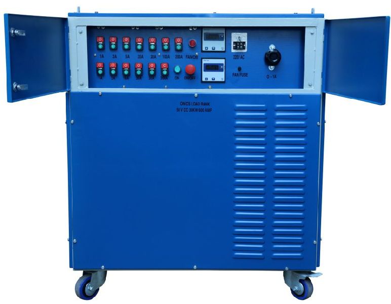
Onics load banks are designed to mimic electrical load such as generator and Ups, etc. in AC And DC circuits. Load banks are designed using specially maufactured elements. The elements are either made of Iron-Chromium-Aluminum alloy or nickel-Chromium alloy. In AC circuits, it can provide both resistive and resistive-reactive loads. Load Banks are fan cooled with over temperature protection for efficient operation.
Features :
Applications :
Where to use onics power resistors :
Features :
Constructions : These resistors are made by winding resistive wire on fibre glass cord or ceramic rods. Terminals are crimped or welded to end caps. This resistor assembly is then encapsulated in ceramic boat with high Temperature and fire retardant cement.
Graph
Technical Details
| Rating at 70oC Watts | Dimensions in mm | Resistance Range | |||
| L | D | d | I | ||
| 2W | 18 | 7 | 0.8 | 35 | 1 OHM – 2 K |
| 3W | 22 | 8 | 0.8 | 35 | 1 OHM – 3 K |
| 5W | 22 | 10 | 0.8 | 35 | .01 OHM – 10K |
| 7W | 35 | 10 | 0.8 | 35 | .01 OHM – 20K |
| 10W | 48 | 10 | 0.8 | 35 | .01 OHM – 30K |
| 15W | 60 | 12 | 0.8 | 35 | .01 OHM – 40K |
| 20W | 60 | 14 | 0.8 | 35 | .01 OHM – 50K |
| 30W | 76 | 19 | Clip Terminals | - | .01 OHM – 60K |
| 40W | 90 | 19 | Clip Terminals | - | .01 OHM – 70K |
Note : Mounting Hardware of 30W & 40W Optional
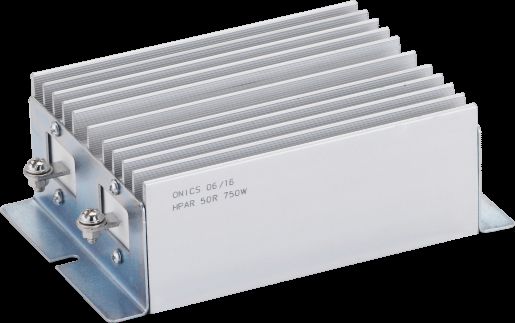
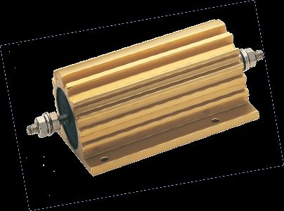
ConstructionAluminium housed Resistor are wound with Nickel Copper or Nickel Chromium wire for obtaining required resistance on a ceramic core fitted with end caps. The winded assembly is then encapsulated in a anodised Heat sink using high temperature moulding compound.
Features
ApplicationThese Resistors are applied where high wattage dissipation is required in a small space. The metal heat sink ensures good heat dispersal & allows a low hot-spot temperature. Major application include Induction furnace, Medical equipments, Humidity Chambers etc.
Deratings
Graph
Dimensions And Weight
| Dimensions In M.M. | Dimensions In M.M. Aluminium Heatsink | Resistance Range | ||||||||||||||||||
|---|---|---|---|---|---|---|---|---|---|---|---|---|---|---|---|---|---|---|---|---|
| Watts | A ± 1.0 | B± 0.25 |
C Max |
D± 0.25 | E± 1.60 | F± 1.00 |
G± 1.00 |
H± 0.80 | L± 0.25 |
J± 0.80 |
K± 0.13 |
L Max |
M± 1.60 |
N± 0.50 |
P Min |
Q± 0.13 |
R | S | T | - |
| 5 | 28.6 | 12.5 | 2 | 11.3 | 1.6 | 6.8 | 8.5 | 12.5 | - | 16.4 | 2.4 | 8.2 | 3.4 | 1.7 | 1.6 | 1.3 | 100 | 100 | 2 | 0.1OHM-500OHM |
| 10 | 34.9 | 15.9 | 2.4 | 14.3 | 19.1 | 7.9 | 10.7 | 15.9 | - | 20.4 | 2.4 | 9.9 | 4.2 | 1.9 | 2 | 2 | 100 | 100 | 2 | 0.1OHM-1K |
| 25 | 50 | 20 | 4.4 | 18.3 | 27 | 11.2 | 14 | 20 | - | 27.5 | 3.18 | 14 | 5.9 | 1.9 | 2 | 2 | 150 | 150 | 1.5 | 0.1OHM-5K |
| 50 | 71 | 21.4 | 5 | 39.8 | 50 | 11.2 | 16 | 21.4 | - | 29 | 3.18 | 15.5 | 7.9 | 2.25 | 2 | 2 | 150 | 150 | 3 | 0.1OHM-10K |
| 100 | 95 | 37 | 15 | 35 | 65 | 15 | 26 | 37 | - | 47 | 5 | 26 | 11 | 3.5 | 4 | - | 150 | 200 | 3 | 0.1OHM-20K |
| 150/200 | 139 | 57 | 9.5 | 70 | 89 | 25 | 46 | 57 | - | 73 | 5 | 45 | 20 | 5 | 5 | - | 150 | 300 | 3 | 0.1OHM-35K |
| 250/300 | 178 | 63.5 | 8 | 98.4 | 115 | 32 | 54 | 63.5 | 76 | 76 | 5 | 56 | 25 | 5 | 6 | - | 300 | 300 | 3 | 0.1OHM-50K |
Additional Information:
Payment Terms : L/C, D/P, T/T
Packaging Details : As per customer requirement.
Delivery Time : 10 TO 15 DAYS