Our Products
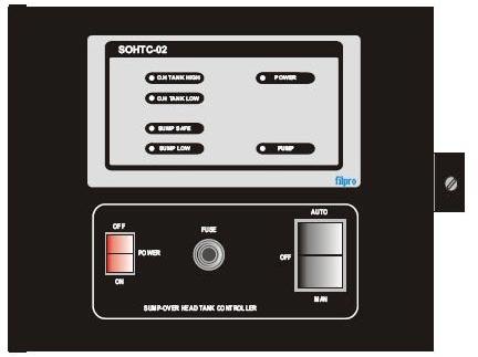
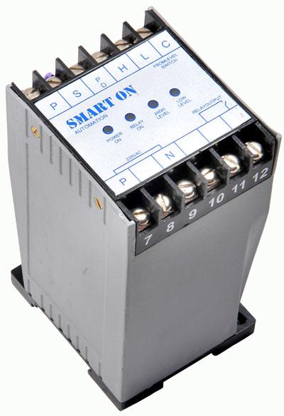
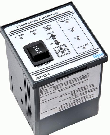
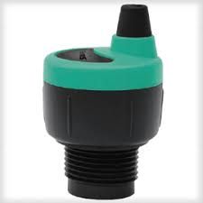
Our Complete range of products are Vibrating Fork, Liquid Level Controller (DLIC-R1), Fuel Tank Level Sensor, Liquid Level Controller (APC-1) and Liquid Level Controller (SOHTC-02).
")
Specifications
| Supply Voltage | 95 - 280V AC, 50 Hz. |
|---|---|
| Power Comsumption | 3VA. |
| Outputs | Pump Relay - 2NO Rated 5A@ 250V AC Resistive Load. Alarm Relay - 1C/O Rated 10A@ 250V Resistive Load. Analogue O/P - 0 - 10V Dc / 15mA. |
| Input | 10 Level Magnetic Float Sensor Probe Resistance :0 - 2.5K Ohms Each Level - 250 Ohms / 4-20mA Input. |
| Facility Available | Pumps mode / Drain mode (p / d ) Programmable. |
| Pump ON Delay | 0 - 250 Secs Programmable |
| Alarm ON Delay | 0 - 250 Secs Programmable |
| Pump Relay Settings | High Level - 10 to 100 % Programmable Low Level - 0 to 90 % Programmable. |
| Alarm Realy Setting | High Level - 10 to 100 % Programmable Low Level - 0 to 90 % Programmable. |
Graph

Working Principle:The vibrating fork type level sensor works on the principle of tuning forks. There is a stack of piezo ceramic crystals located inside the fork assembly. The stack is so selected that on application of voltage, the crystals oscillate at the natural frequency of the fork assembly. This frequency is continuously monitored by the internal electronic circuitry. When the fork comes in contact with liquids, the frequency slightly changes, and this change is sensed by the electronics which in turn send out a signal. This signal is processed to give out a transistor output or relay output etc as the case may be.
Key Advantages:This assembly is immune to the type of application which could have foam, variable flow, bubbles, contamination, liquid properties, presence of solids etc in the sensing liquid. It does not need any frequent calibration or adjustments and once installed and commissioned, it is free to operate for-ever. Since the forks are under constant vibration, the probability of any sticky material or floating solvents sticking to it is minimal. Also, it is free from influences of temperatures and pressures.
Applications:The vibrating fork sensor can be used for virtually every type of liquid level measurement application where point level is of importance. This could be for overfill level, low or high level, pump protection from dry run, applications which require high levels of hygiene, RF based wireless applications etc. Since the fork is made from SS 316 L, it is free from corrosion or aging, and can even be used in food industries etc.
Mounting:For best results, it is recommended that correct installation practice is followed. 1. The fork fingers should not be directly under the discharge location of liquids into the tank. 2. If used for solid medium, a protecting canopy above the fingers is recommended. 3. The face plates of the fingers should be vertical in side mount applications. See figure attached for further clarity. 4. It is allowed to mount the assembly slightly tilted to the horizontal, this will help in preventing material build up. 5. While mounting from top of the tank, axis orientation of face plates of the fork does not matter. 6. The complete fork should protrude into the tank, and not part of it, and there should be no side cavity. The purpose is to avoid material build up inside cavities.