Our Products
Our offered Product range includes High Pressure Control Valve, Steam Conditioning Valve and Turbine Bypass Valves/Systems.
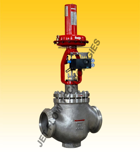
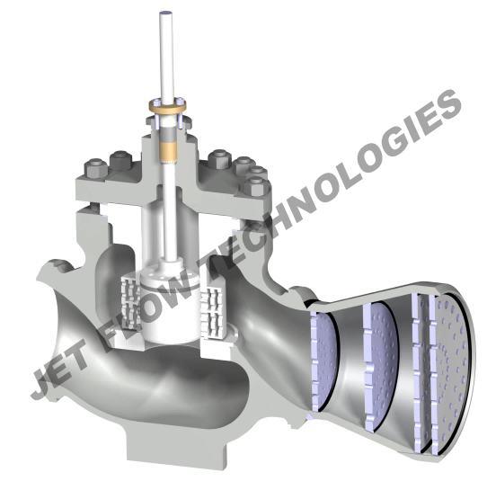
A Steam Conditioning Valve / Combined PRDS Valve is the combination of pressure reduction and temperature reduction of superheated steam to fit process needs, protect downstream equipment or allow the use of less expensive materials or schedules for downstream piping. This is done with a pressure reducing valve and a spray water addition section either as separate units or a single device. Pressure reduction is carried out with a pressure reducing trim within the valve body, usually multi stage pressure reduction. The pressure is controlled by an upstream or downstream pressure controller, signaling the valve to modulate to maintain the pressure at the required set point.Temperature is controlled by adding water to the steam in such away that it will get fully evaporated in the steam, termed as desuperheatmg.
These applications are normally considered to be some of the most severe services of any valves in a modem steam plant.
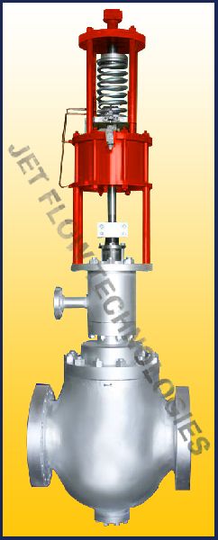
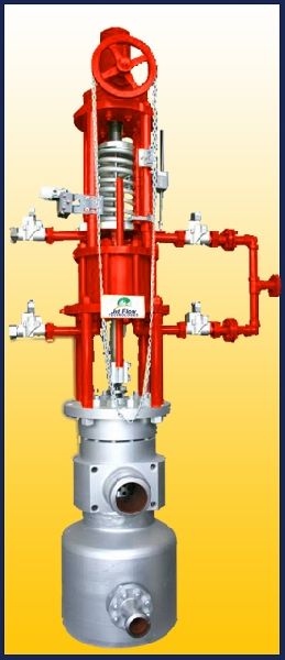
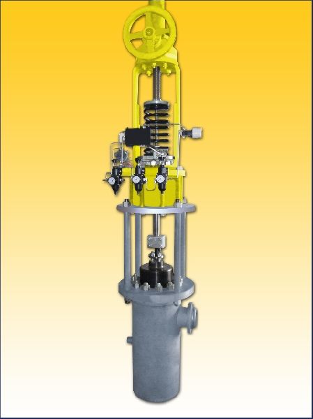
A Steam Conditioning Valve Jet Flow steam conditioning valve with revolutionary multinozzle atomizer and feed forward design adds to our latest generation of quality valves. The equipment is utilised for simultaneous pressure and temperature reduction of steam. The cooling water is introduced in the highest turbulent zone of the steam. High steam velocity at this point, results in the highest coefficient of heat transfer between the steam and water. The feed forward design assures soft misty spray and instantaneous temperature control over the full range of steam flow.
Steam Conditioning Valve Jet Flow steam conditioning valves are available in a variety of combinations. These valves are made as per tailor made requirements of customers. The valves are manufactured in angle, Z and globe forms. Spray water entry is from the top through hollow stem as well as from the bottom, depending upon the process parameters.
Applications are but not limited to:
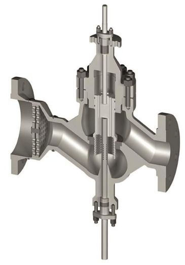
Multi-Stage Multi-Path Pressure Reduction via Velocity Control trim technology:
Applications:
Advantage of Jet Flow Steam Conditioning Valvewith Jet Stack Velocity Control trim and laval jet nozzle -
Requirements -
Graph 01
Graph 02
Graph 03
Specification
| Bill of Material | |
| Item Description | Material |
| Nozzle Insert | A182 GR F11 / F22 / F91 |
| Body (Lower Part) | A182 GR F11 / F22 / F91 |
| CW INLET | A105 |
| DISC | DIN 1.4122 PLASMA NITRIDED / INCONNEL 718 |
| CONE / PUG | DIN 1.4122 PLASMA NITRIDED / INCONNEL 718 |
| SEAT | DIN 1.4122 PLASMA NITRIDED / A 182GR F11 / F22 / F91 ST |
| MAIN BODY | A 182 GR F11 / F22 / F91 |
| CAGE / INLET CYCINDER | DIN 1.4122 PLASMA NITRIDED |
| STEM | DIN 1.4122 PLASMA NITRIDED / INCONNEL 718 |
| PISTON RINGS | X120 Cr 29 |
| SEALS | GRAFOIL |
| BONNET / COVER | A182 GR F11 / F22 / F91 |
| BONNET / FLANGE | A 182 GR F11 / F22 / F91 |
| ---- | |
| Other grades of material are also used depending upon design requirements. | |
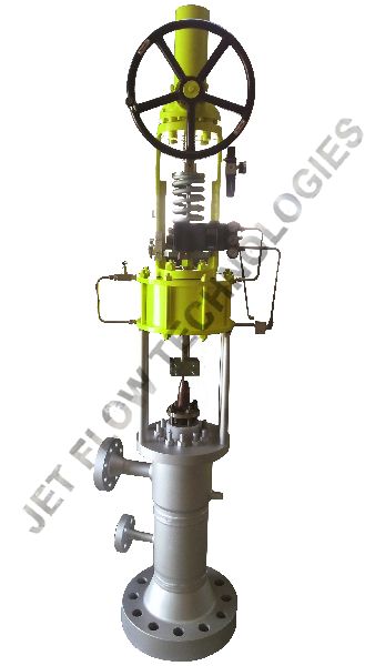
Turbine bypass valves play a very major role in Power Plant applications. Within a short period of twenty four hours, a power plant may be required to operate at minimum load, increase to maximum capacity for major part of the day, immediately lower back to minimum load and then back to maximum capacity. Bypass System permit unit start up and shutdown in a lifesaving manner for critical heavy components in boiler and turbines. Jet Flow Bypass valves are supplied with hydraulic, electric or pneumatic actuators as per the process requirements alongwith complete control systems as an option.
Functions:
Applications:
There are two different applications:1) Bypass Systems which are occasionally in operation. Among these there are startup and shutdown conditions and emergency conditions, for example after turbine trip.2) Bypass System which are often or permanently in operation, for example for process steam or heating application.
Actuators:
Bypass valves can be supplied with Pneumatic Piston & Cylinder, Electric or Hydraulic Actuators alongwith power pack and complete control system as per the requirements of the system.
Materials:
For most sizes, casting or forgings in Carbon and Alloy Steel can be supplied. For extremely large sizes, units are fabricated. Bypass Valves are normally supplied with butt weld ends. However, if required can be supplied with flanged ends.
Multi-Stage Multi-Path Pressure Reduction via Velocity Control trim technology:
Advantage of Jet Flow Turbine Bypass Valves with Jet Stack Velocity Control trim and laval jet nozzle -