Our Products
Our offered Product range includes RRH Flow Transmitter, VHZ Flow Transmitter, Omni-XF Flow Transmitter, LABO-XF-I/U/F/C Flow Transmitter and RRI-032RMH Flow Transmitter.

Flow Transmitter RRH :
Characteristics : The flow meter consists of a spinner which is rotated by the flowing medium. The rotor's rotational speed is proportional to the flow volume per unit time. The rotor is fitted with magnets. A Hall sensor records the rotational speed, which is proportional to the flow rate.
Wiring : Air bubbles affect the measurement results. For filling processes, the valve should be installed behind the sensor. A running up time of approx. 0.5 seconds and a running down time of approx. 3 seconds should be noted.
Handling and operation :
InstallationThe Rototron device is installed in the pipework with the aid of the rotatable adapter pieces. If necessary, the adapters can be removed from the body of the housing after the stainless steel clips have been removed from the housing. Before reinstalling, it should be ensured that both the adapter with the O-ring and the sealing surface in the body are clean and undamaged. The adapters should be fitted carefully in the housing (it is best to turn them), so that the O-ring is not damaged. With this flow sensor, there is no need for run-in and run-out sections. However, it should be ensured that the flow sensor is at all times filled with medium. Any preferred installation position is possible, but the best possible venting position should be chosen (rotor axis horizontal, flow horizontal or from bottom to top).
Options :
Accessories :

Details :
Characteristics :
Wiring : Before the electrical installation, it must be ensured that the supply voltage complies with the data sheet. The use of shielded cabling is recommended.
Handling and Operation
Installation : The VHZ flow measurement device can be installed anywhere in the pipework system. A run-in section is not required. The direction of flow may be freely chosen. It should be ensured that no dirt particles (thread cutting swarf!) can get into the flow space, as this could cause the blockage of the gearwheels. It may therefore be necessary to install filters upstream of the flow measurement device (mesh size 30 μm).
Options : Highest temperature 120oC
Accessories :

Flow Transmitter / Switch OMNI-XF
Characteristics :
Option C : Preset Counter with external reset option, complementary switchingoutputs and actual value display.
Option C1 : Instantaneous value display with analogue output, pulse-volumeoutput and totalizer
Options : Through a range of options, the XF system is flexibly adaptable to very varied requirements.
Full metal construction
High temperature : If the full metal model is fitted with high temperature sensors and a gooseneck, operation at media temperatures up to 150oC is possible.
Note : Operation using the plastic body is also possible at temperatures greater than 70oC. However, it should be noted that this reduces the stability to pressure .
Resistance to backflows :

A very versatile reliable flow switch using a dynamic diaphragm made of stainless steel, which covers the whole cross section of the pipe and is deflected by the flow, which is then detected by a sensor.
100 bar High pressure Version AvailableA very versatile reliable flow switch using a dynamic diaphragm made of stainless steel, which covers the whole cross section of the pipe and is deflected by the flow, which is then detected by a sensor.
Features:

Features:

Features:
Flow Transmitter RRI :
Characteristics : The flow meter consists of a spinner which is rotated by the flowing medium. The rotor's rotational speed is proportional to the flow volume per unit time. The rotor is fitted with stainless steel clamps (optionally titanium or Hastelloy. An inductive proximity switch records the rotational speed, which is proportional to the flow rate.
Wiring : the valve should be installed behind the sensor. A running up time of approx. 0.5 seconds and a running down time of approx. 3 seconds should be noted.
Handling and operationThe Rototron device is installed in the pipework with the aid of the rotatable adapter pieces. If necessary, the adapters can be removed from the body of the housing after the stainless steel clips have been removed from the housing. Before reinstalling, it should be ensured that both the adapter with the O-ring and the sealing surface in the body are clean and undamaged. The adapters should be fitted carefully in the housing (it is best to turn them), so that the O-ring is not damaged. With this flow sensor, there is no need for run-in and run-out sections. However, it should be ensured that the flow sensor is at all times filled with medium. Any preferred installation position is possible, but the best possible venting position should be chosen (rotor axis horizontal, flow horizontal or from bottom to top). Air bubbles affect the measurement results. For filling processes
Options : Rotor with titanium clamps
Accessories :

A very versatile reliable flow switch using a dynamic diaphragm made of stainless steel, which covers the whole cross section of the pipe and is deflected by the flow, which is then detected by a sensor.
100 bar High pressure Version AvailableA very versatile reliable flow switch using a dynamic diaphragm made of stainless steel, which covers the whole cross section of the pipe and is deflected by the flow, which is then detected by a sensor.
Features:

Model No:
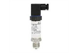
Suitable for applications in potentially explosive atmospheres. These pressure transmitters are designed for highest industrial requirements and have have ATEX approvals.
Specifications:
Measuring ranges -1…1000 bar
Output: 4.20 mA
ATEX-approved
Devices for Ex areasSuitable for applications in potentially explosive atmospheres. These pressure transmitters are designed for highest industrial requirements and have have ATEX approvals.
Measuring ranges -1…1000 bar
Output: 4.20 mA
ATEX-approved
Devices for Ex areasSuitable for applications in potentially explosive atmospheres. These pressure transmitters are designed for highest industrial requirements and have have ATEX approvals.
Measuring ranges -1…1000 bar
Output: 4.20 mA
ATEX-approved
Devices for Ex areas

Details :
Handling and operation : The vortex flow meter requires a run-in length of 5.10 x D in order to achieve its specified accuracy. If deposits are to be expected, sensor and electronics should not be installed underneath. It should be ensured that the sensor is installed in the direction of the flow arrow. If the sensor is to be cleaned, the clamps should be released, and the device removed (the pipe should be pressure-free for this). It should be ensured during cleaning that the oscillating vortex body is not exposed to impact (in the moulded part there is a sensitive piezo-ceramic sensor, which can break).
Accessories :
Flow Transmitter / Switch OMNI-VHZ :
Characteristics :
Option C : Preset Counter with external reset option, complementary switching outputs and actual value display.
Option C1 : Instantaneous value display with analogue output, pulse-volume output and totalizer
Handling and operation : The VHZ flow measurement device can be installed anywhere in the pipework system. A run-in section is not required. The direction of flow may be freely chosen. It should be ensured that no dirt particles (thread cutting swarf) can get into the flow space, as this could cause the blockage of the gearwheels. It may therefore be necessary to install filters upstream of the flow measurement device (mesh size 30 μm).
Programming :The annular gap of the programming ring can be turned to positions 1 and 2. The following actions are possible :
Overload display : Overload of a switching output is detected and indicated on the display ("Check S 1 / S 2"), and the switching output is switched off.
Simulation mode : To simplify commissioning, the sensor provides a simulation mode for the analog output. It is possible to create a programmable value in the range 0.26.0 mA at the output (without modifying the process variable). This allows the wiring run between the sensor and the downstream electronics to be tested during commissioning. This mode is accessed by means of Code 311
Factory settings : After modifying the configuration parameters, it is possible to reset them to the factory settings at any time using Code 989.
Options :
Accessories :

Details :
Characteristics :
Handling and Operation :
Installation : As with all flow meters, if possible the turbine should be installed ahead of a valve (on the pressure side). Good degassing should be ensured. 10 x D calming sections are recommended before and after the turbine in order to maintain the specified accuracies. The turbine should be filled with fluid at all times. The electronics housing does not project into the flow space.
Options :
Accessories :

