Company Information
Ask for more detail from the seller
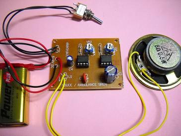
Contact SupplierThe Police Ambulance Siren Circuit uses two No. 555 ICs and generates police/ ambulance siren. Here, is the circuit diagram of a police siren based on NE555 timer IC. The circuit uses two NE555 timers ICs and each of them are wired as astable multi vibrator. The circuit can be powered from anything between 6 to 12V DC and is fairly loud. By connecting an additional power amplifier at the output, you can further increase the loudness. IC1 is wired as a slow astable multi vibrator operating at around 20Hz @ 50% duty cycle and IC2 is wired as fast astable multi vibrator operating at around 600Hz.The output of first astable multi vibrator is connected to the control voltage input (pin5) of IC2. This makes the output of IC2 modulated by the output frequency of IC1, giving a siren effect. In simple words, the output frequency of IC2 is controlled by the output of IC1. The component arrangement is low frequency and extension of production low frequency is obtained from IC1 connected to astable multi vibrator circuit frequency is set by R1, C2 frequencies that are coming out of pin 6,7 is about 20 Hz through the circuit of IC1, a division produce high-frequency input at Pin 5 will tone the origin of oscillator IC2 is the ripple of voltage from the output of IC1 frequency of IC2 is being set by R2, C3, which, if C3 value. It will be very low tone if C3 is less treble.

Connect with us