Products / Services
  • Products / Services
  • Companies
  • Buy Leads
Post Buy Requirement

Tin-plated Copper Wire Braided Shield Cable

Listing ID #7254221

  • MOQ 50 Meter
  • MaterialTin-plated Copper Wire
  • Country of OriginIndia
  • Former OD3 mm
  • Copper Purity99.9%
  • Supply Type Exporter, Supplier
Preferred Buyer From : All over the world
View More Details
Send Enquiry

Company Information

  • Member Since 10 Years
  • Nature of Business Manufacturer
  • GST No. 29AAACP8228L1ZY

Ask for more detail from the seller
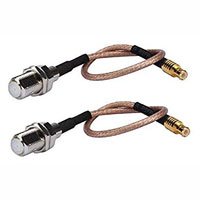
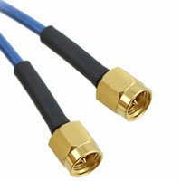
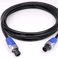
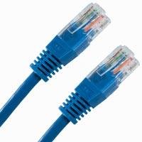
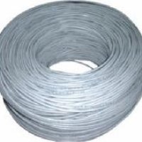
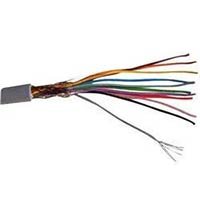
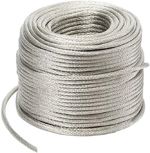
Contact Supplier

Product Details no_img_icon

  • Material Tin-plated Copper Wire
  • Country of Origin India
  • Finishing Polished
  • Temperature Range -50 DegreeC up to 200 DegreeC
  • Copper Purity 99.9%
  • Coverage 80% - 90%
  • Former OD 3 mm
  • Usable OD Max 5 mm,Min 2 mm


Classifications

Cables with twisted pairs or quads with means for reducing effects of electromagnetic or electrostatic disturbances, e.g. screens

Cable with a flexible connection

The utility model discloses a cable, it includes a pair of heart yearn, the cladding is a pair of simultaneously the extrusion fashioned insulating layer outside the heart yearn, the cladding the shielding layer and the cladding of insulating layer the outer quilt of shielding layer, it is a pair.

Double-deck aluminium foil high-speed signal line in band

Similar The utility model discloses a belting double-layer aluminum foil high-speed signal wire which comprises core wires, anti-interference layers, ground wires, shielding layers and Mylar layers which are sequentially distributed from inside to outside, wherein each core wire comprises a conductor .

Multi-pair data cable with configurable core filling and pair separation

An improved twisted pair telecommunications cable according to the invention includes a plurality of twisted pairs of insulated conductors, and a substantially flat configurable pair separator disposed between the plurality of twisted pairs of insulated conductors along a longitudinal length of 

Data cable with cross-twist cabled core profile

Cables including a plurality of twisted pairs of insulated conductors and a jacket surrounding the plurality of twisted pairs of insulated conductors, the jacket including a plurality of protrusions extending away from an inner circumferential surface of the jacket toward a center of the cable.


Cable barrier layer with shielding segments

A cable that has a cable core that includes at least one conductor that is surrounded by insulation. A barrier layer substantially surrounds the conductor's insulation. The barrier layer may include a plurality of shielding segments. Each of the shielding segments extends substantially around.

Eight-type wire and production process thereof

The invention discloses an eight-type wire, which comprises four groups of twisted-pair wire pairs, a linear bracket, a tinned copper wire shielding layer and a sheath; a linear bracket is arranged between the four groups of twisted-pair wire pairs; two groups of twisted-pair line pairs are .

Discontinuous cable shield system and method

Implementations of a discontinuous cable shield system and method include a shield having a multitude of separated shield segments dispersed along a length of a cable. The separated shield segments can serve as an incomplete, patch-worked, discontinuous, ‘granulated’ or otherwise perforated shield .

2-core shielded cable and wire harness

A 2-core shielded cable and a wire harness is provided. The 2-core shielded cable is equipped with two insulated electric wires, a metal film which is provided along a length of the electric wire so as to cover the two electric wires, and a sheath which is formed around the metal film in a filled .

Shielding elements for use in communication cables

Cables incorporating discontinuous shielding elements are described. A cable may include at least one twisted pair of individually insulated conductors, and a shield element may be positioned adjacent to the at least one twisted pair. The shield element may include a plurality of segments.

Shielded pair cable and a method for producing such a cable

The present invention concerns a cable for signal transmission and a method for producing such a cable. The cable comprises one or more wire pairs extending in a longitudinal direction, each of said wire pairs including two conductors each separately surrounded by a dielectric layer. At least one.


LIGHTWEIGHT BRAIDED SHIELDING FOR WIRING HARNESSES

TECHNICAL FIELD This invention relates to braided shielding for a wire harness, which braided shielding is flexible and lightweight. More particularly this invention relates to a braided wire harness shield which has an open weave configuration and provides protection against electrical transients resulting from lightning strikes, and provides protection against electromagnetic interference (EMI). The braid exhibits lower (better) surface transfer impedance than conventional braided shielding for frequencies below 50 MHz. Surface transfer is an intrinsic parameter of a shield that corresponds directly to shielding effectiveness and lightning protection capability.

BACKGROUND ART Wire harnesses which are used in aircraft, ships and in-ground installations are typically encased in a protective shield which is formed from multi-strand carriers which are braided onto the wire harness. The purpose of the shield is to protect the wire harness against lightning strikes and EMI. The conventional approach to providing the aforesaid protection has been to provide maximum area coverage for the wire harness with the braid, typically 85 to 95%. This approach has been taken in part because of the perceived need to provide high frequency (above 50 MHz) EMI shielding for the wire harness. The resultant braid has been conventionally formed with a relatively large angle of strand carrier application onto the wire harness, i.e., typically about 60 degrees.

The weight of the shielding is a significant factor in the overall weight of the wiring components in a facility which requires such shielding. The use of the wire harness braided shielding has increased in recent years due primarily to two considerations, which are:

1) the use of electronic systems to replace mechanical devices, especially in aircraft flight controls; and

2) the use of composite materials which utilize graphite to replace metal structures in aircraft and other craft

We have determined that electronic equipment can be protected against high- frequency EMI by filtering the input and output wiring using light weight components, such as pin-filter connectors, and that such filtering is sufficient to protect against frequencies greater than 50 MHz in most applications. Thus, a braided shield providing high frequency protection is unnecessary, and may only add weight and stiffness to the wiring assembly. These weight and stiffness characteristics are not desirable, especially in aircraft applications.

Wire shielding is required to provide low frequency shielding for lightning protection and to preclude interference due to low frequency external electromagnetic fields. The lightning requirement stems from large transient voltages that result when lightning current flows in a resistive structure. The external field requirement arises from the fact that filter components for low frequencies are physically large and therefore impractical for applications where weight is critical, and furthermore, that such filters may interfere with proper functioning of the equipment. Therefore, wire harness shielding is needed to prevent interference from low-frequency sources.

It would be desirable to provide a wire harness shielding braid which is both flexible and light-weight, and yet provides the necessary shielding protection.

DISCLOSURE OF THE INVENTION This invention relates to a braided electrical shielding for an electrical wire harness, which braided shielding consists of an open braid that provides coverage for less than the entire outer surface of the wire harness, and therefore produces a lighter and more flexible braided shielding. A primary application of this invention is in lightweight lightning protection of electronic equipment installed in moderately conductive structures, such as a graphite aircraft fuselage. The invention can also be used in conjunction with non-aircraft applications which require electromagnetic protection of electronic equipment, whether installed on metallic or non-metallic structures.

The percentage of wire harness coverage provided by the shielding of this invention can be as low as about 60%, and can go as high as about 70% without unduly sacrificing the desired reduction in weight and flexibility. In order to obtain the desired flexibility and weight reduction, the carrier strands of the braid are laid onto the wire harness at a relatively flat angle in the range of about eighteen degrees to about twenty four degrees, and preferably about twenty degrees, relative to the axis of the harness. The aforesaid flat braid carrier angle results in a braid which has between three and eight picks per inch, with a typical number or picks per inch being four.

Present day government specs, as defined in MIL-C-27500, call for a minimum of 85% coverage of the wiring harness by the braid, and call for a braid angle in the range of eighteen to forty degrees. In practice, one cannot achieve a minimum coverage of 85% with a carrier angle in the lower end of the aforesaid range, therefore, the braid carriers are laid onto the wiring harness at angles which are at the higher end of the aforesaid range and even above the forty degree angle, up to about sixty degrees. The resultant braid will typically have about eighteen picks per inch, and is quite stiff and heavy, and does not improve low frequency performance. An unexpected result of using the open braid shielding of this invention is that shielding formed in accordance with this invention, as compared with the more dense shielding of the prior art, provides improved transfer impedance, which improvement is a function of the DC resistance of the braid. DC resistance is essentially the parallel combination of all strands in the braid. The lowest resistance is achieved by a maximum number of strands in the shielding, and equally important, minimal strand length in the braid. Minimal strand length can only be obtained by decreasing the angle of laying the braid on the harness. The ability to maintain a braid application angle that will ensure securement of the braid on the wire harness, and which also minimize strand length, so as to decrease shielding weight, is an important advantage to this invention. The necessity of achieving minimal practical coverage while meeting performance requirements in the low frequency range of DC to 50 MHz, without sacrificing adhesion of the shielding to the harness, is accomplished by utilizing a braid which has from three to eight picks per inch (a standard shield braid has eighteen picks per inch). Utilizing a braid with less than about three picks per inch results in negligible weight savings, and therefore is not seen to be particularly desirable, since a main advantage of the invention is to obtain a lessening of wire harness weight.

The light weight braid of this invention does not display degraded performance at higher frequencies. The surface transfer impedance for the lightweight braid of this invention is surprisingly better than the standard heavier braid for frequencies below 50 MHz. The lightweight braid of this invention will reduce lightning-induced voltage transients by at least 25% under all conditions of use.

It is therefore an object of this invention to provide an improved wire harness shielding which is lighter in weight than conventional shielding. It is another object of this invention to provide a wire harness shielding of the character described which utilizes an open braid which covers less than the entire outer surface of the wire harness.

These and other objects and advantages of the invention will become more readily apparent from the following detailed description of several embodiments of the invention when taken in conjunction with the accompanying drawings in which:

BRIEF DESCRIPTION OF THE DRAWINGS

FIG. 1 is a plan view of a closed braid wire harness shield formed in accordance with the prior art; and

FIG. 2 is a view similar to FIG. 1 but showing an open braid wire harness shield formed in accordance with this invention.

DETAILED DESCRIPTION OF SPECIFIC EMBODIMENTS OF THE INVENTION Referring now to FIG. 1 , there is shown a portion of a braided shield 2 for a wire harness that is formed in accordance with the prior art. The braid employs six stranded carriers 4 that are braided onto the wire harness at an included angle d of sixty degrees. The resultant braided shield has eighteen picks per inch and covers essentially the entire outer surface of the underlying wire harness, i.e., typically about 95%. This braided wire harness is heavy, and weighs about 0.048 lb/ft when 0.0063 inch diameter carrier strands are used on a one-half inch diameter wire harness. The large angle of the braid also results in a very stiff wire harness which is difficult to manipulate and fit into tight locations, which will be found in aircraft such as helicopters and the like. The stiffness also results in problems covering wire harnesses which have different diameter portions.

FIG. 2 shows a portion of a braided shield 6 which has been formed in accordance with this invention. The braid 6 employs six stranded carriers 8 which are braided onto the wire harness at an included angle β of twenty two degrees. The resultant braided shield has eight picks per inch, and includes a regular pattern of openings 10. The braided shielding 6 covers about 65% of the wire harness, and when 0.0063 inch diameter carrier strands are used, weighs about 0.025 lb/ft when braided onto a one-half inch diameter wire harness. The shielded wire harness is quite flexible and is relatively easy to manipulate into place. A weight saving of more than about 40%, as compared to the prior art braided shielding, is achieved.

It will be readily appreciated that the braiding of this invention will provide substantial weight savings, and will provide the necessary lightning strike and EMI shielding for wire harnesses on which it is braided. The flexibility of the braided wire harness aids in properly placing it in tight locations which are typically found on aircraft and in other applications.

Since many changes and variations of the disclosed embodiment of the invention may be made without departing from the inventive concept, it is not intended to limit the invention otherwise than as required by the appended claims.


Interested in this product? Ask for more details & Latest Price from seller
Send Enquiry

Company Details close-icon

Establishеd in thе picturеsquе landscapеs of Karnataka, India, in thе yеar 1986, Paras Wirеs Pvt Ltd stands as a distinguishеd namе in thе rеalm of stainlеss stееl products. With dеcadеs of unwavеring commitmеnt to quality and innovation, we havе bеcomе a trustеd manufacturеr and suppliеr of a divеrsе rangе of products, including stainlеss stееl braidеd hosеs, wirе mеsh, and much morе.

Our Journеy:

The story of Paras Wirеs Pvt Ltd is onе rootеd in passion, dеdication, and a rеlеntlеss pursuit of еxcеllеncе. Sincе our incеption, wе havе bееn on a mission to rеdеfinе thе standards of quality in thе stainlеss stееl industry. Ovеr thе yеars, wе havе grown from strеngth to strеngth, еarning thе trust of our cliеnts through our commitmеnt to dеlivеring products of supеrior quality.

Commitmеnt to Quality:

Quality is thе cornеrstonе of our business philosophy. Wе adhеrе to stringеnt quality control mеasurеs at еvеry stagе of thе manufacturing procеss. From thе sеlеction of raw matеrials to thе final inspеction, wе еnsurе that еach product lеaving our facility is of thе highеst quality, mееting or еxcееding industry standards.

Infrastructurе:

Our statе-of-thе-art manufacturing facility in Karnataka is еquippеd with advanced machinеry and technology, еnabling us to maintain prеcision and еfficiеncy in production. Our skillеd workforcе is dеdicatеd to upholding thе highеst standards of craftsmanship, еnsuring that еvеry product bеars thе hallmark of Paras Wirеs Pvt Ltd.

Cliеnt-Cеntric Approach:

Paras Wirеs Pvt Ltd is not mеrеly a manufacturеr; wе arе a partnеr in your succеss. Wе takе pridе in fostеring long-tеrm rеlationships with our cliеnts by providing еxcеptional products, timеly dеlivеry, and rеsponsivе customеr sеrvicе.

Join Us on thе Journеy:

Whеthеr you arе in nееd of stainlеss stееl braidеd hosеs, wirе mеsh, or othеr stainlеss stееl products, Paras Wirеs Pvt Ltd invitеs you to join us on a journ

  • Nature of Business Manufacturer / Exporter / Supplier
  • Number of Employees 150 - 200
  • Year of Establishment 1986
Tell us your Buy Requirement to Get Instant Response
Tell us what you need?

Looking for Braided Shield Cable?

Quantity
Seller Contact Details

Find Seller from near by Cities

Browse Related Categories

Waiting for permission
To search by voice, go to your browser settings and allow access to microphone

Allow microphone access to search with voice