Company Information
Ask for more detail from the seller
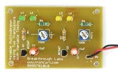
Contact SupplierDancing LED Using Transistors DIY Kits (Not Soldered)
An Dancing LED using Astable Multivibrator is a simple hobby circuit which has no stable states. Its output oscillates continuously between its two unstable states without the aid of external triggering. The time period of each states are determined by Resistor Capacitor ( RC ) time constant.
When the circuit is switched on one transistor will driven to saturation (ON) and other will driven to cutoff (OFF). When a transistor is ON, its collector and emitter act as a short circuit. But when it is OFF they acts as open circuit. So in the above circuit when a transistor is in OFF state its collector will have the voltage Vcc and when it is ON its collector will be grounded.Consider Q1 is ON and Q2 is OFF. During this time Capacitor C2 is charging to Vcc through resistor R2. Transistor Q2 is OFF due to the negative voltage from the discharging capacitor C1 which is charged during the previous cycle. After a time period the capacitor C1 discharges completely and starts charging in reverse direction through R1.When the Capacitor C1 charges to a voltage sufficient provide base emitter voltage of 0.7V to the transistor Q2, it turns ON and capacitor C2 starts discharging. The negative voltage from the capacitor C2 turns off the transistor Q1 and the capacitor C1 starts charging from Vcc through resistor R and base emitter of transistor Q2. Thus the transistor Q2 remains in ON state. As in the previous state, when the capacitor C2 discharges completely it starts charging towards opposite direction through R2. When the voltage across the capacitor C2 is sufficient to turn ON transistor Q1, Q1 will turn ON and capacitor C1 starts discharging.This process continuous and produces rectangular waves at the collector of each transistors.
As a result Output LEDs flashing with charging & discharging time period.
T1=0.693R1C1
T2=0.693R2C2

Connect with us