Listing ID #1346757
Company Information
Ask for more detail from the seller
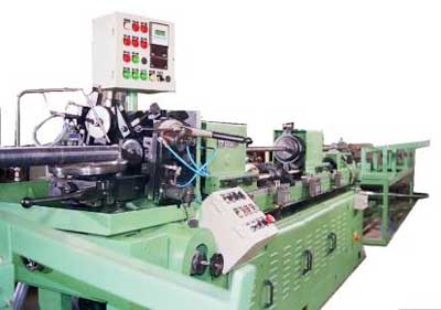
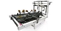
Contact SupplierIn heat exchangers use fin tubes to increase heat precipitation efficiency by 5 to 6times.The machine is developed for manufacture of finned tubes. The machine is basically capable of manufacturing various kinds of finned tubes like Embedded fins (Gfins), wrap around (L and LL fins), knurled, soldered fins, etc. Main purposes of the machines, the process of continuous finning. There is no limitation of the length of tube being finned. Also it is suitable for continuous production where in tubes can be fed continuously one after the other.
In heat exchangers use fin tubes to increase heat precipitation efficiency by 5 to 6times.The machine is developed for manufacture of finned tubes. The machine is basically capable of manufacturing various kinds of finned tubes like Embedded fins (Gfins), wrap around (L and LL fins), knurled, soldered fins, etc.
Main purposes of the machines, the process of continuous finning. There is no limitation of the length of tube being finned. Also it is suitable for continuous production where in tubes can be fed continuously one after the other. central out put shaft is square drive shaft driving the two spindles (for tube rotation) and the other to drive shafts are coupled to the two lead screws of the two driving head respectively. There are two driving heads (LH & RH) which are driven by two shafts. These heads work alternatively to move the pipe in forward direction one after the other. These heads provide the required Pitch-feed movement of the tube. The spindles are hollow and the tube being fed passes right through them which pass through them. Both the heads are provided with a pneumatically operated collet chucks. The Chuck cylinders are operated through pneumatic solenoids provided. At any time one of the head either front or the rear will be driving and the other head will be waiting except for a short distance at the end of the stroke of each head when both will be driving. First head will clamp the tube and drive at the required pitch speed (for e.g. 11 FPI) till end of its stroke (approx. 450 mm). Before the end by actuation of a limit switch the second head will catch the tube and start moving forward at the required pitch feed when the first head will release the tube before its stroke end and returns to its home position and awaits to repeat the cycle ( return speed is always faster than forward motion). Such continuous actions of two heads lead to continuous feed of the tube. For this both heads are provided with a forward and reverse clutch and brake. Clutches are inside the main gear box while the brake is outside.
Also proper limit switch/proximity arrangements are provided for sensing the end of tube when the fining is to be stopped and also when the new tubes are to be joined. During these operations the machine automatically slows down and stops. The fining is continuous process of winding the fin over the tube. Hence continuous feed of fin material is very important. For this two bobbins are provided at the rear of machine below the input rack. The bobbins are kept at an inclined plane for the ease of operation. At any given time one of the bobbins is operational while other is used for the loading of the new coil and keeping it ready for next use when the fin becomes empty on the first one. Both the bobbins are provided with Hydro-pneumatic brakes actuated whenever the main motor stops so that the bobbins brake immediately without causing the fin to get loose or break. The fin from bobbin is fed through a series of guides to the front of the machine. Where a pneumatic lubricating and tensioning unit is provided. The felt pad of the unit is well lubricated to provide the adequate quantity of oil film on the fin. Further fin winds 90 deg. around the roller and passes through a fin guide mechanism to the fining area. The strip guide varies based on the type of fining and also acts as a forming tool for L and LL fins. Basically as the fin is wound around the tube is automatically pulled through the strip feed arrangement and the arrangement ensures straightening of fins and also not allow fins to break and also it is fed with the required formation. The fining mechanism ensures the process of proper fin formation on the tube and also the total fining operation.
It basically has four main components namely
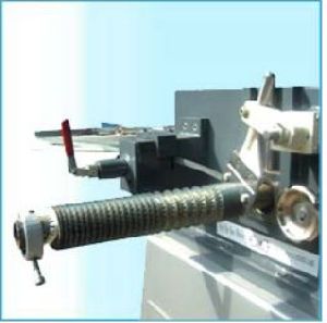
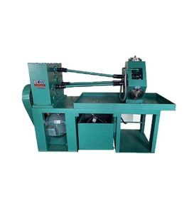
Pan wheel and Pressure wheel are situated below the tube in the fining area at the front of the machine. Pan wheel is the larger wheel and this presses at required angle and pressure against the smaller Pressure wheel. The fin gets squeezed between the two and the subsequent elongatio results in the fining action. The fin is squeezed more at its periphery and almost not squeezed at all at its root wound over the tube. To achieve this machine has the provision for setting the pan wheel angle through the handle at the front of the machine.
Also the toggle lever for the pan wheel ensures the right pressure for squeezing. This can be adjusted through the fine screw provided at the front near the Pan. The height of both pressure and pan wheel is adjustable based on the tube diameter and the type of fining. The Pan wheel and pressure wheel both are driven by the main motor itself. For this the drive from the square shaft is transmitted through a series of gear boxes and belt drives. In front towards the operator a variable speed drive with an easy adjustment handle is provided where in the operator can easily adjust the ratio between the pan wheel speed and the spindle speed. The proper adjustment of this ensures correct fin feed to ensure proper winding of fin over the tube. The grooving and penning wheel are required for G- type fining only. Both are fixed on different arms at an angle above the tube. Grooving tool is on an arm towards the operator and while penning is away from operator. Both of them have both manual and pneumatic operation. The pneumatic operation is for short stroke while manual operation is for adjusting the pressure and also totally with drawing them.
The grooving tool makes a continuous thread like formation on the tool However it is more an action of Plugging as it actually doe snot cut the material but forms a Groove with metal build up on either side. In process the grooving is done just before the fining. The root of the fin formed (being wound) enters the groove as it is getting formed and is helically wound only into the grove.The penning wheel immediately presses the material build up back into the grove. In the process it virtually holds the root of the fin creating a mechanical bonding between the tube and the fin.
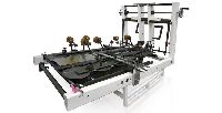
Both the grooving tool and penning wheel have provision for adjusting the required angle of helix and also the pitch distance from the pan wheel. Both are also provided with pneumatic retraction cylinders of short stroke. They are useful for programmed with drawl of the tools during end of tube so that operator can pass over to next tube and start again. And also for the intermittent fining action where in fining is done for the required lengths only. The Machine is provided with an Input tube rack of adequate length as required to hold the tubes ready for fining and also guide the tube being finned.
For this a long V channel lined with soft material is provided. The V is supported on a series of elevating screw jacks actuated by a single common handle. The height is set based on the dia of the tube. The racks also have a arrangement for stacking few tubes on an inclined plane. When the new tube has to be joined the operator operates the required button where in one tube is lowered on to the V through pneumatic cylinders provided.Between the input rack and the machine a sensor is provided to sense the presence of tube length of the tube being fed into the machine. As the remaining length is out of the V Rack the machine slows down and stops after a short duration of travel when the new tube is coupled to the tube being fed through the machine. Coupling of new tube is must for complete fining of the tube being finned.
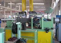
The Out put Rack is a three roller system. It closely guides the finned tube which is very essential to ensure proper fining of long tubes and also no damage to the finned tube. The position of the rollers is adjustable based on diameter as explained later. The alignment of the rack is particularly important and proper care should be taken to align properly. The rack also has adjustable proximities for the end of the tube sensing. It has two sensors one for nearing the end when the machine slows down and the other for the end when the machine would stop.
Most of the actuations of the machine is achieved through the pneumatic cylinders provided. This includes the chuck operation, penning and grooving wheels, brake, tube loading, strip lubrication etc. All the pneumatic cylinder functions are controlled from the PLC through the solenoid valves. Where ever required we have used double solenoids detent type to ensure the actuation is not disturbed in the event of power failure. All the pneumatic valves are fixed at rear front of the machine just before the fining area. Also we have provided a FRL unit for the pneumatic. A minimum pressure of 5 bar is essential for the correct operation of the machine. If the pressure drops below the same it is sensed by the pressure switch provided and machine will stop automatically. The machine is provided with automatic centralized lubrication. For this a self contained motorized pumping unit is provided at the rear side of the machine.
The oil is distributed to various points required through the pipes. For every point a Metering cartridge is provided which ensures a correct dosage of oil. The pump is switched on periodically when the correct required oil flows once to every point. The interval of switching on is controlled by the PLC. If the oil level in the tank of the unit falls below the minimum level the machine will stop and it has to be filled for the machine to work again. This is indicated also by the lamp provided on the indicator panel. The fining machine is provided with a coolant system consisting of a coolant tank, pump, and delivery and return hoses. The coolant whenever switched on is delivered in required quantity controlled through the valve to the grooving tool. It is collected back to the coolant tank.
| OVERALL DIMENSIONS | 3900 X 950 X HEIGHT 1600 |
|---|---|
| WEIGHT | 3000 KG. |
| INPUT RACK DIMENSIONS/WT | 940 X 1200 X HEIGHT 14000 |
| OUT PUT RACK DIMENSIONS/WT | 1104X 1470 X HEIGHT 15600 |
| DRIVE MOTOR | 11 KW |
| INVERTER DRIVE FOR MAIN | ALLEN BRADELY MAKE |
| ELECTRICAL SUPPLY | 415 VOLT, 3 PHASE, 50 HERTZ WITH NEUTRAL AND EARTHING |
| COMPRESSED AIR SUPPLY | 5.5 BAR 400 L/ MIN. |
| MAXIMUM TUBE SIZE | 50.8 MM |
| MINIMUM TUBE SIZE | 12.7 MM "L" FIN, 19MM "G" FIN |
| MAXIMUM FIN HEIGHT | 19 MM |
| MINIMUM FIN HEIGHT | 6.3 MM |
| FIN PITCHES | THEORETICAL: 6.5, 8.0, 9.0, 10, 11, 12.5. :ACTUAL: 6.44, 7.98, 8.9, 10.07, 11.1, 12.48. (FINS PER INCH) |
| BOBBIN | 2 NOS, DIA 1500 MM |
| GROOVING TOOL CYL STROKE PEENING WHEEL STROKE/ PEENING WHEEL SWING EITHER SIDE | 2 MM / 4 DEGREE (MAX) |
| TOTAL CONNECTED LOAD IN KW/HP | 13 / 18 KW / HP |
| MAXIMUM CURRENT | 26 AMPS |
| INPUT SUPPLY | 3 PHASE, 415V, 50HZ WITH NEUTRAL AND EARTH |
| CONTROL VOLTAGE | 24 VDC, 230VAC |
| AC INPUT CABLE SIZE | 6 SQMM 4 CORE + EARTH |
| MAX INPUT FUSES | 63A HRC |
| DESCRIPTION OF THE MACHINE | made for fining of Aluminum strip onto 1no of Steel pipe of max 100mm using 2nos of heads and 1no of Grooving, penning, pan wheel in 6 different pitches and heights Between 10-15mm. |

Connect with us