Company Information
Ask for more detail from the seller
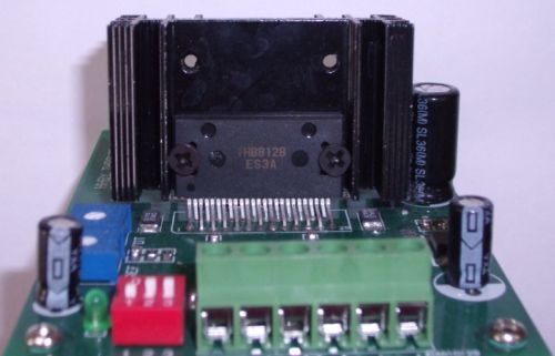
Contact SupplierWe are offering test board for stepper motor driver ic.
terminal instructions
signal interface for the signal-input control
clk+: the positive of the pulse signal input interface
clk-: the negative of the pulse signal input interface
cww+: the positive of the motor' positive/reversal rotation control interface
cww-: the negative of the motor' positive/reversal rotation control interface
ena+: the positive of the motor' offline control interface
ena-: the negative of the motor' offline control interface
the connection of the motor winding
out1a: connect the a phase of the motor winding
out2a: connect the a- phase of the motor winding
out1b: connect the b phase of the motor winding
out2b: connect the b- phase of the motor winding
the connection of the operation voltage
vm: positive for the connection of the dc power
gnd: negative for the connection of the dc power
input signal interface
input signals are consistent with three lines: (1) stepping pulse signals of clk+ and clk-; (2) direction electric-level signal of cww+ and cww-; (3) offline signals of ena+ and ena-. They have the same interface circuits in the motor (see input signal interface schematic) and independent with each other.
the feature of the input signal interface is that it can be connected with shared positive or shared negative according to users' need.
Shared positive connection: connect the clk+, cww+ and ena+ separately to the power that controls the system. If the current level is just 5v, it can be connected directly. However, if the current is above 5v, there will a current limiting resistor needed outside the motor so as to supply a sustained drive current between 8 ~ 15ma for the optical coupling inside the motor. Add the input signals through clk- while the cww- and ena- is performing at the moment at a low electric level.
Shared negative connection: connect the clk-, cww- and ena- separately to the ground interface of the control system (sgnd, isolated from the power ground), the +5v input signals will be added by clk+, while this moment cww+ and ena+ is performing at a high electric level. The interpretation of the current limiting resistor is as the same of the shared positive connection.
The setting of the micro-stepping number
you can use the dial-turntable switch on the motor to set the micro-stepping number, just follow the setting instructions on the subdivision table. Please as far as possible to use high subdivision under the load of the system's frequency. After that, you can calculate the stepping the stepping motor's step angle as follows: step angle=motorâ��s constant step angle/micro-stepping number. For example 1.8â°/40=0.045â°
m3 m2 m1 subdivision
on on on 2
on on off 8
on off on 16
on off off 32
off on on 64
off on off 128
off off on 10
off off off 5
the setting of the motor�s phase current
the phase current is set by the motor�s potentiometers(vref),so as to make the motor�s output current is accordance with motor�s phase current. The limited max current for the motor is 4 a.
The setting of the current attenuation method
according to the input voltage of fdt terminal, the fast-decay mode, slow-decay mode or mixed �decay mode can be set up.
Fdt voltage decay method
above 3.5v slow decay
1.1v-3.1v or open mixed decay
0-0.8v fast decay

Connect with us