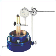
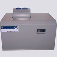
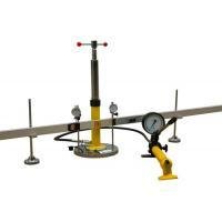
This test is necessary for drainage application. The permeameters can be of parallel flow or radial flow type. In either case, flow occurs along the plane of the permeameters. In the apparatus, flow occurs radially outwards, from a central hole to the periphery of a circular specimen. The transmissivity is defined as the volumetric rate of flow per unit width of geotextile and unit hydraulic head.
Specifications
Flow: Radially outwards
Specimen diameter: 100 mm
Range of Pressure: Upto 800 kPa
Head of Water: Upto 30 cm
Optional
Overhead Tank
Loading unit, 300 kPa capacity
SGE-1012
Thickness Gauge
Thickness is one of the basic physical properties used to control the quality of many geotextiles and geosynthetic. This equipment is simple to operate and thickness of the geosynthetic / reinforcing material can be measured with an accuracy of 0.002 mm for thickness upto 10 mm. Accuracy is 0.01 mm for thickness greater than 10 mm. Simple mechanism is provided to apply desired foot pressure varying from 1 to 10 kPa as per various international standards. Surface plate is grounded and is rust free to enable reproducible results.
SGE-1013
Universal Testing System for Geotextiles
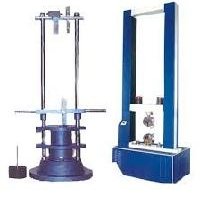
The evaluation of the tensile properties of geotextiles is of paramount importance not only in reinforcement application but also in all other uses. Important properties include stress-strain behaviour, ultimate strength in uniaxial tension (under different widths), creep, etc. Recent researches have made it clear that the measured stress-strain behaviour of geotextiles is significantly influenced by details of testing procedures like method of gripping the fabric, rate of deformation, sample size / aspect ratio, initial preload and fabric conditioning. Universal Testing System for Geotextiles enables determination of these properties under a variety of test conditions. The 100 kN capacity systems have speed ranges from 5 to 320 mm/min. The following attachments are available for this system at extra cost.
SGE-1014
Universal Testing System for Geotextile with Digital Indicater
SGE-1013001
Narrow and Wide Width Tensile Strength
Two clamping systems 8 cm wide and 22.5 cm wide are mechanical wedge type and facilitate conducting Narrow Strip and Wide Width Tensile Strength tests as per many international specifications, viz Indian, British, ASTM etc. These grips allow simple and rapid sample loading. Roller type grips required in high strength geotextile testing can be supplied as optional extra.
SGE-1013002
Grab Tensile Strength Test
This test measures the ability of the geotextile to distribute concentrated loads. Specially devised clamps (25 mm wide) with a gauge length of 100 mm are placed across 200 mm square samples or 200 mm x100 mm samples. The sample is then subjected to tension at a specified rate until failure occurs. It is widely used by manufacturers as a quality control tool and as such is the most commonly reported tensile strength value. It can also be used for relative comparisons between geotextiles of the same type.
SGE-1013003
Trapezoidal Tear Resistance Test
Geotextiles can be cut or punctured during field installation, which can create a possible condition by which strength is controlled by a tearing resistance. In the method suggested by ASTM-D4632, an outline of an isosceles trapezoid is marked on a rectangular specimen (150 mm x 75 mm) cut for the determination of tearing strength, (with a 6 to 9 mm cut) and the non-parallel sides of the trapezoid marked on the specimen are clamped in parallel jaws of the Tensile Testing System. Thereby, the separation of the jaws is continuously increased with simultaneous recording of the load, so the tear propagates across the specimen. The tearing strength is the value for estimating the relative tear resistance of different geotextiles or different directions of the same fabric
SGE-1013004
CBR Push Through Test
In this test developed in West Germany (DIN-54307 E), fabric is clamped to give an inner diameter of 15 cm and a standard CBR plunger is pushed centrally through a fabric at a specified rate. The load at failure is the push through load and when divided by the cross-sectional area of the plunger, gives CBR push through resistance. This gives the resistance of fabric to withstand localised pressure, which is particularly noticed in pavement systems.

 Member Since 16 Years
 Nature of Business Manufacturer
 Address C-14/1 Wazir Pur Industrial Area Delhi, Wazirpur, Delhi, 110052, IN
 Number of Employees 6 - 20






 For Buyer
  For Seller
  Help
Help 
 Twitter
 WhatsApp
 Facebook
 Linkedin