Company Information
Ask for more detail from the seller
Contact SupplierBacked by efficient logistics team, we make deliveries of the goods in the set time span. Our prime interest is to deliver a flawless range of products to the buyers. And in this concern, we make all arrangements in order to store the entire lot under safe environment.
Features
Working principle
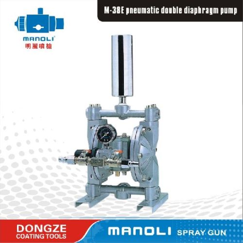
The double diaphragm pump is driven by compressed air, nitrogen gas and natural gas. The main directional pneumatic control valve distributes compressed air to the gas cavity and uniformly pressures the inner surface of the diaphragm. At the same time, gas is exhausted out via the guide outlet of air valve components from the rear of the other side of the pump. The pressure in gas cavity exceeds the pressure in fluid cavity, so that the connecting rod moves backwards and forwards, resulting in sucking from one side and exhausting out from the other side.
The direction of exhausting out and sucking fluids is in the charge of the direction of the check valve (ball valve or flap valve). Intake stroke makes the pump suck. Intake stroke reduces the pressure of cavities and increases their volumes, which results in pressure difference driving fluids to pass through the suction tube and suction check valve and flow into the outer fluid cavity.
Intake stroke drives the pump to move reciprocally (motion, stroke and circulation). The pneumatic double diaphragm pulled by the stroke machine sucks the moving diaphragm. The inner board the diaphragm pump touches the aligned driving piston, and then the movement is delivered to the center of the valve. After being activated, the guide valve shows a signal of pressure to the other side of the main directional control valve, and then the diaphragm pump changes the direction of compressed air to the other side of inner cavities.
In this way, the diaphragm pump works repeatedly, so fluids or materials are conveyed continually.
| Model | Type | Ratio | Fluid nipple size IN | Maximum fluid working pressure MPa (kgf/cm2) | Spraying air pressure MPa (kgf/cm2) | Maximum viscosity available | Fluid pressure stabilizing valve | Fluid filter | Maximum output l/min | Pump material | Diaphragm material | Weight kg |
|---|---|---|---|---|---|---|---|---|---|---|---|---|
| M-38E | Lightweight | 1.1 | 3/8″ | 0.15 , 0.69 (1.5 - 7) | 0.15 , 0.69 (1.5 - 7) | below 60 seconds using NK-2 viscosity cup | ------ | ------ | 1.6 | Aluminum alloy | Teflon | 7 |
| M-38R | Fluid pressure stabilization | LFR-405 | ------ | 2 | 8.5 | |||||||
| M-38FR | Pressure stabilization and filtration | LFR-405 | LFR-405 | 2 | 9.2 |

Connect with us