Company Information
Ask for more detail from the seller
Contact SupplierThe 555IC Tester is used to test most widely used 555IC. The use of Timer IC555 proves its importance in almost most of the circuits. So it becomes necessary to build such a design to test this most popular IC. Although the IC555 is generally very reliable, there are occasions when malfunction does occur. The circuit shown here will provide a simple and effective method of testing suspect devices.
About the Circuit :
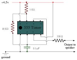
The timer to be tested, IC1 is connected as an astable multivibrator. When the push to test button ‘S1’ is closed, capacitor C1 will start to charge up via resistors R1 and R2/P1. As soon as the voltage level on this capacitor reaches the trigger point of the timer, the internal flip-flop is activated and pin7 is taken low to discharge C1. The flip-flop is reset when the voltage on C1 reaches the threshold level of IC1. This takes pin7 high and the charge cycle starts once more.
The output of the timer pin3 is connected to a pair of light emitting diodes. When the output is high, LED D2 will be ON and D1 will be off. Conversely, when the output is low D1 will be ON and D2 will be OFF. The LED will flash ON and OFF alternately provided, of course, that the IC under test is a good one.
For readers who may have other application for the circuit and who wish to alter the frequency, the rate at which the LED flash is determined by the values of R1,
R2/P1 and C1. The frequency of oscillation can be calculated from the formula
f = 1.44/(R1+2(R2+P1))C1
If, as in this case, the value of R2 is much greater than the value of R1, the frequency can be approximated from the following
f = 0.72/(R2+P1)C1

Connect with us