Product Category : Digital Communication Lab Trainer (Series : 200-B)
Product Name : QAM Modulation & Demodulation
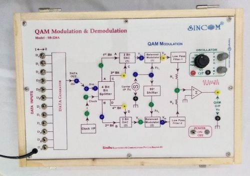
Model No. : SB-224
Product Details
QAM Modulation: This circuit has four bit Data Splitter, 2-bit DACs, two Balance modulators wired using IC 1496, 900 RC Phase shifter network, two low pass filters and OP-AMP IC 741 as summing amplifier. The 12 bit digital data input with clock input is applied to four bit Data splitter network to split the data into four bits, which is then applied in pair to respective 2-bit DAC and balanced modulators with direct and 900carrier input to provide balance modulator outputs which is after LPF and summing network provides QAM modulated data output. On board 12 bit digital Data generator, Clock input, Sine wave carrier signal generators (1No) with variable frequency upto 100KHz and 10Vpp amplitude. facility to change the digital data input bits and carrier input. facility to connect external clock and data input. variation in phase and amplitude of carrier for the given data input pattern. 4-QAM system, maximum carrier frequency 50KHz, Discrete level circuit. QAM Demodulation: This circuit is wired with two mixers, 900 RC Phase shifter, two low pass filters, logical decision device circuit, multiplexers and OP-Amps to form QAM Demodulation circuit to provide the demodulated serial data output with minimum noise for the applied QAM input signal. QAM input, Digital Data input 12 bit, carrier reference input, maximum carrier input frequency 50KHz, QAM detector bandwidth upto 2KHz, Discrete level circuit, Built-in fixed DC ±12V/+5V/1A Power supply and maximum test point.
Objectives :
To Study the Quadrature Amplitude Modulation (QAM).
To observe & note the change in QAM O/P w.r.t. the change in digital Data I/P.
To observe & note the change in QAM O/P w.r.t. the change in Carrier I/P.
To Study the Quadrature Amplitude Demodulation.
To observe the note demodulated O/P w.r.t. change in modulating digital Data I/P.
To observe and note the change in the O/P w.r.t. change in carrier I/P.
To observe and note the distortion/error in O/P w.r.t change in applied digital data I/P.
Accessories Included : Set of Patch Cords, Operating Manual.