Listing ID #961556
Company Information
Ask for more detail from the seller
Contact SupplierDouble Direction Automation Of Manless Railway Gate is related to automation in railways. Automation Of Man-Less Railway Gate (Double Direction) is designed to avoid railway accidents by notifying the arriving of trains to the station masters. Automation Of Man-Less Railway Gate (Double Direction) automatically detects the arrival of train and GATE opens. Also, as the train passes, it automatically closes the GATE. The circuit is very simple. Automation Of Man-Less Railway Gate (Double Direction) is constructed using Infrared transmitter and receiver. The use of an infrared light source is an oblivious choice for this type of application. For this application, the light beam must be invisible, which limits the choice to infrared or ultraviolet light. Ultraviolet light can cause visible fluorescence of certain materials, which makes it less suitable than infrared. In the second place, relatively powerful solid-state infrared sources and infrared sensors are available at modest cost, whereas there are no solid-state UV sources commercially available. The circuit uses here infrared LED and photodiode.
Although these devices are not exorbitantly priced, neither are they inexpensive, so in order to minimize the number of IR emitters necessary to achieve a given range the transmission system should be as efficient as possible. Since the light level received at several meters distance from the transmitter will be very low, the receiver must have a high gain. This immediately excludes the simpler types of photoelectric switch that use a continuous light beam and a DC coupled receiver. Since a high gain DC coupled receiver amplifier would be prone to offsets, temperature drift and other effects that could lead to poor sensitivity. The choice therefore falls on AC modulated light beam and AC coupled receiver.
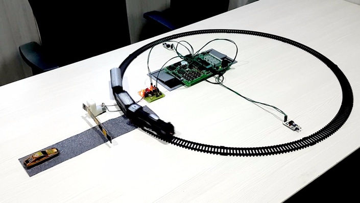
The infrared sensors that is infrared LED and photodiode are aligned such that light beam from infrared LED directly falls on photodiode. The distance of separation should be in the range of 2 to 3 mtrs or less. When the train arrives, the IR radiations emitted by infrared transmitter and falling on photodiode are interrupted. As a result, receiver circuit detects this. The important feature of this circuit is that it can detect the train in both directions. The direction sensitive circuit is used to detect the arrival and passing of train in both directions. Alarm and Motor driver circuit is used to drive the motor and raises the alarm by connecting an electric bell to relay switch. The motor used here is a DC motor, which rotates clockwise and anticlockwise and in turn drives the railway gate.
About the Circuit :
As stated earlier the circuit is built around Infrared transmitter and receiver circuit. It requires two pair of the transmitter and receiver. The first pair is kept at some distance from the station at one end. And the other pair is arranged at some distance at opposite end. For perfect execution of the circuit the distance between block A & block B should be greater than the length of the train . For driving motor, driver stage is designed using four transistors as shown in figure. When T1 and T2 gets triggered, motor rotates in one direction. And when T3 and T4 gets triggered, it rotates in other direction. The details of transmitter and receiver circuit are given below.
Transmitter Circuit :
The simple transmitter circuit is shown in figure. It consists of 555 timer connected as an astable multi vibrator, driving an output transistor which switches the IR emitter on and off. The duration of the transmitted light pulses is about 10ms and repetition rate is just less than 1 KHz. The average current drawn by the circuit is about 12mA and the peak current through the IR diode is about 700mA.
The power supply for the transmitter is not critical provided the output voltage is no greater than 9V, as this could result in the maximum current rating of IR diode being exceeded. The specifications and other details are same for other transmitter module.
Receiver Circuit :
The receiver circuit is shown in figure. An infrared photodiode is operated in the reverse bias mode. The leakage current of this diode varies with the light received from the transmitter, which causes a varying voltage to appear across resistor R2, the base resistor of T1. The signal appearing at the source of T1 is fed to IC1, which is used as an amplifier and limiter, P1 varies the sensitivity by altering the reverse bias voltage of the diode.
When light pulses are being received from the transmitter, a negative-going pulse train with amplitude in excess of 1V peak-to-peak appears at the output of IC1 (pin8). This turns T2 on and off continuously, charging up C11, T3 is thus always turned ON, transistor T4 is turned OFF and the logic circuit is not energized motor remains OFF.
When the train arrives from block A to block B, The light beam between the transmitter and receiver is interrupted at point A, the amplitude of the pulse train from the output of IC1 will fall, transistor T2 will be cut off, C11 will discharge. Transistor T3 will turn off and T4 will turn on. A shortly logic low pulse is applied to gate IC1. The other input of Gate receives from another IR receiver circuit. The output of gate goes high and a logic high pulse is given to clock input of IC2. As clock input transits from low to high the Q1 output of IC2 goes high. Thus, the low output is given to trigger input pin2 of IC4, which acts as a one shot multi vibrator. The output of IC4 pin3 goes high for a period determined by timing components using R6/P1/C5, which can be adjusted by preset P1 of logic card. Driver transistor T1 and T2 conducts which drives motor and the motor is on as long as pin3 of IC4 is high.. At the same time transistor T5 turns on, relay gets energized which switches on bell. Also LED D9 glows which gives visual indication. When the train passes, other IR beam gets interrupted at point B, and the receiver circuit is on which gives another clock pulse to counter IC2. The next output of decade counter goes high, IC5, which is a one shot multivibrator IC gets triggered and its output goes high for a period determined by timing components designed around R7/P2/C6. The period is adjusted by preset P2 of logic card. Driver transistor T3/T4 conducts and motor rotates in another direction. Thus if gate is closed in first interruption, the gate opens in another interruption. It must be noted that the period of rotation should be same in both interruptions. Now the counter IC gets reset.
When the train goes from block B to block A, point B is interrupted first. IC2 receives first clock pulse and motor rotates in clockwise direction. When point A is interrupted, IC2 receives another clock pulse and motor rotates in anticlockwise direction. Thus the gate is controlled in both directions.
Construction :
When constructing the receiver, great care must be taken with the layout due to the high sensitivity and large bandwidth. The leads to photodiode must be as short as possible, as otherwise, they may peak interference. Since the photodiode is sensitive to visible as well as infrared light, it must be fitted with an infrared filter. Direct sunlight should not be allowed to fall on photodiode, since its large infrared content could affect the diode biasing and hence the receiver sensitivity.
Calibration :
The transmitter diode and receiver diode should be aligned with one another, although the radiation pattern of the one and the acceptance angle of the other are so wide that the slight misalignment will have little effect. The circuit is then checked for reliable operation at close range by breaking the infrared light beam, after which the transmitter and receiver are moved progressively further and further apart, whilst P1 is adjusted to obtain the maximum range. If the photodiode is well screened from ambient light, this adjustment will have little effect and the wiper of P1 can simply be turned clockwise.
As it stands, the circuit will function at distance of up to 3 mtrs between the transmitter and receiver. If lenses are used to concentrate the transmitted light into a much narrower beam and to focus the received light on the photodiode then much greater ranges can be achieved. However the physical alignment of the transmitter and receiver will then be much more critical.


Connect with us