Products / Services
  • Products / Services
  • Companies
  • Buy Leads
Post Buy Requirement

Transformer Oil Filtration Plant

Listing ID #1607688

  • Supply Type Manufacturer, Exporter, Supplier
Preferred Buyer From : All over the world

Our oil filtration plants are used to remove impurities from transformer and switchgear oil such as moisture, dirt, air and other gases. This is a `low temperature and high vacuum` principle based....
View More Details
Send Enquiry

Company Information

  • Member Since 14 Years
  • Nature of Business Retailer
  • Year of Establishment 2010

Ask for more detail from the seller
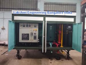
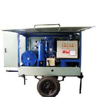
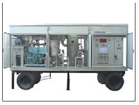
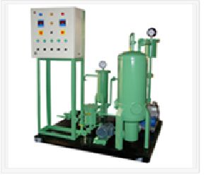
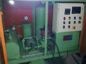
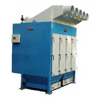
Contact Supplier

Product Details no_img_icon

Our oil filtration plants are used to remove impurities from transformer and switchgear oil such as moisture, dirt, air and other gases. This is a `low temperature and high vacuum` principle based equipment as per the International Standards 6034 (1989) and its latest revision. We manufacture plants of variable capacities of 1200 to 25,000 lph which can be customized to special capacities if required by the clients. This plant takes the impure oil into the system through the inlet ball valve and then pumps it through by a positive displacement pump. A filter prior to this removes solid particles up to 1mm size and magnetic particles. After heating the oil up to 60°c it passes through the cartridge filters, where particles up to 5 microns are filtered. A specially designed vacuum chamber removes moisture, air and all the gases with the help of vacuum. The oil falls by way of gravity over the media inside forming a thin film of oil, exposing a larger surface area. The dissolved moisture and gases are evacuated and the oil is ready.


High-Vacuum Transformer Oil Filtration and Dehydration Plants
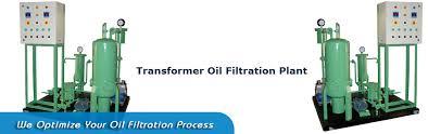
Our Oil Filtration Plants are used to remove impurities from transformer and switchgear oil such as moisture, dirt, air and other dissolved gases. This is a `Low Temperature and High Vacuum` principle based equipment as per the International Standards 6034 (1989) and its latest revision. We manufacture plants of variable capacities of 600 to 25000 LPH which can be customized to special capacities if required by the clients. This plant takes the impure oil into the system through the inlet ball valve and then pumps it through by a positive displacement pump. A filter prior to this removes solid particles up to 1mm size and magnetic particles. After heating the oil up to 60°C t passes through the cartridge filters, where particles up to 5 microns are filtered. A specially designed vacuum chamber removes moisture, air and all the gases with the help of vacuum. The oil falls by way of gravity over the media inside forming a thin film of oil, exposing a larger surface area. The dissolved moisture and gases are evacuated and the oil is ready.
 
Transformer Oil Filtration and Dehydration Plants / Purifiers are available for
Transformer and Capacitor Manufacturers – Skid mounted plants for preparation of new oils prior to apparatus filling and impregnation.
Transformer Repairers - Complete plants for preparation of new oils and regeneration of used oils for reuse. We can provide the purification system you need as well as vacuum storage tanks and transformer filling and emptying / pumping station.
Transformer Owners - Portable plants are available in a variety of trailer-types and sizes to allow on-site servicing of transformer oil right in the substation. Trailers are available with a wide variety of options including laboratory space, oil-testing equipment. Plants are designed for drying out of the transformer insulation and oil filling and impregnation under vacuum. Hot oil circulation and hot oil spray methods can also be used.
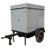
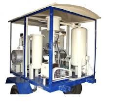
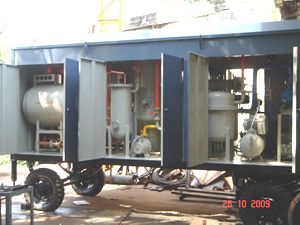
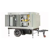
The filtration plant will be designed for high vacuum & low temperature of oil for achieving required results.
The plant will be Mobile, to be mounted on your Vehicle or Skid Mounted, with or without enclosure, suitable for outdoor or indoor use.
All components will have adequate strength & rigidity to withstand normal conditions of handling & transport.
 
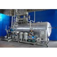
The plant will consist of the following :
Inlet Pump
 
A 600 to 25000 LPH capacity positive displacement gear type pump will be provided. The pump will be suitable for vacuum & continuous trouble free operation. A pressure release valve will be provided across the gear pump, to control the accidental pressure rise in the plant.
 
Capacity – 600 to 25000 LPH
Operating Pressure - 2 Bar
Suction - 4-5 mtrs
By pass arrangement will be provided in between Inlet & Outlet
 
Heaters
  Nicrome or Kanthal wire heater elements inserted in refractory formers will be provided in protection tubes to avoid localized overheating, hot spot formation & breaking of oil. Heaters will be capable of heating oil from 200 C. to 600 C., as recommended in IS 6034 – 1989. Total heater power will be 9 to 248 kW divided into two/three groups. Each group of heaters will be controlled by TIC. An additional thermostat will be provided as a safety to control the temperature during accidental temperature rise.
The surface density of the heater pipes will not be more than 2.5 watts/cm2.
A drain valve for the heater tank will be provided.
 
Indirect type, Wound elements placed in ceramic formers located in Protection Tubes.
Heater Power : 9 to 248 KW.
A Pressure Safety Valve & a Drain Valve will be provided.
A Control Thermostat and a Safety Thermostat will be provided.
 
Filtration System
  Filtration system will consist of the following,
 
A Preliminary filter
 
This filter will be provided to prevent any damage to inlet pump by straining magnetic & all other particles above 1mm size. The cleaning of the filter is possible without dismantling the filter from the pipeline.
  Cleanable without dismantling
 
Flow capacity – 600 to 25000 LPH
Rating - 50 mm
Arrests magnetic particles
B Pre-Filter
 
Filters will be easily changeable. It will be suitable for removal of particles larger than 20 microns. It will be suitable for removal of sludge content in the used oil. This will enhance the life of fine filter.
C Cartridge Filter (fine filter)
 
Throw away type, non-hygroscopic cartridge filter elements of one-micron rating will be provided. The cartridges are easy for replacement & have large dust holding capacity.
  Cartridge Filter (fine) placed in a steel housing.
 
Flow capacity – 600 to 25000 LPH
Rating - 1 Micron
 
Ionic Reaction Column
 
An Ionic Reaction Column of 10 to 40 Kg activated alumina will be provided for reduce the acidity in the oil. A bypass arrangement will be provide for after first filling with IRC.
 
Degassing Chamber (Single Stage as well as Two Stage)
 
It will be of M.S. welded construction. The chamber will be designed to withstand the suitable vacuum. In the degassing chamber, dissolved gases & moisture from the oil will be removed. A specially designed media will be provided in the degassing chamber to offer maximum surface area, to form a thin film of oil, to achieve maximum possible removal of dissolved gases & moisture at the rated flow rate. One high level & one low level float switch will be provided to control the oil level in the degassing chamber.
  Two stages will be separated by a siphon seal.
Highly efficient Two Stage degasser packed with Raschig Rings & equipped with the following :
 
Totally Welded
Sight Glass & Lamp Shade
Raschig Ring Trays
Low Level and High Level Float Switches
Level Sensor will provided in Degassing Chamber
 
Outlet Pump
 
A centrifugal pump will be provided at the outlet. The capacity of the pump will be 12000 LPH and it will be suitable for sucking oil from degassing chamber, held under vacuum.
 
Capacity - 12000 LPH.
Discharge Head - 8 Mtrs
 
Vacuum Pumping System
  A combination of roots & rotary vacuum pumps will be provided for evacuation of degassing chamber. 
An additional connection with an isolation valve will be provided in the system, to facilitate evacuation of transformer tank, simultaneously.
The vacuum pumping system will be equipped with all-necessary accessories like Vapour trap, condenser, valves & gauges etc.
The specifications of the vacuum pumps will be as follows:
 
Rotary Oil Sealed Pump
Pumping speed (Minimum)
Ultimate vacuum
Make Indo Vacuum/Dicon/Tuthill/Leybold/Woo Sung/ Shinko Seiki/Reputed
  Mechanical Booster (Roots) Pump
 
Pumping speed (Minimum)
Ultimate vacuum
Make Indo Vacuum/Dicon/Tuthill/Leybold/Woo Sung/ Shinko Seiki/Reputed
  The Vacuum System will be equipped with the following :
 
Vacuum Gauge (Bourdon Type), Range: 0 to -760 mm of Hg
Vacuum Gauge (Digital Type), Range: 1 Torr
Airing Valve
Non return Valve
 
Cooling System
 
For cooling, a condenser will be provided in the vacuum line. A condenser will be provided, to maintain ambient temperature of the water which will be circulated through this condenser for collecting water in to the trap. One water tank will be provided in to the top of the mobile van having capacity to hold 100 liter water.
 
Non Return Valve
  One non return valve will be provided at the inlet and one at the outlet, which will prevent mixing of filtered & unfiltered oil, in case of power failure.
 
Valve & Piping
 
Two airing valves will be provided for airing the vacuum system. All inline valves will be Ball Valve in case of Fully Automatic System then Valves will Solenoid Valves with carbon steel body & S.S. ball, suitable for vacuum application.
 
Oil & Vacuum Valves will be of Solenoid type or Ball Valve.
Piping will be of Normal Steel.
Mechanical Non Return Valves before Degassing Column & at Plant outlet
Oil Sampling Valve
Isolation Valve at Plant Inlet & Outlet
 
One pressure gauge at the inlet of the cartridge filter will be provided. One bourdon type vacuum gauge & one digital gauge (for measurement of fine vacuum) will be provided in the vacuum system.
Independent electric drives will be provided for all pumps. Motors will confirm generally to is 325 (testing) & will be of CGL / Hindustan Motors / Siemens or any other reputed make. Starters will be of direct on line type.
 
Control Panel
 
The enclosure will be fabricated out of CRCA sheets & will be suitably coated to protect from weather. All electrical control gears, mains isolating arrangement, starters, contactors, pilot lamps, push buttons, HRC fuses, relays, indicating lamps and interlocking arrangements will be housed in the enclosure. All wiring will be neatly routed & all wire terminations will be suitably identified with ferrules.
A tube light will be provided for plant illumination. The plant will be suitable for operation on 415 V, 3 Phase, 50 Hz. A.C. supply.

Incoming Power Supply Cable for Control Panel is to be arranged by the Customer and is not included in scope of our supply.
  Electrical Interlocks
 
The inlet pump will be interlocked with the heaters, in such a way that unless the oil is actually flowing in the system, the heaters cannot be energized. The electrical interlock between heater supply and motor supply will also be provided so that as soon as the inlet motor trip due to some fault in the drive/due to supply failure, the heater supply will also be automatically cut off.
In case of power failures, electro magnetically operated inlet and outlet solenoid valves will be closed and prevent oil from entering the degassing chamber. The moment oil inlet pump or discharge pump is switched on the corresponding valves will open automatically.
The suction pump and the level controller in the degassing chamber will be interlocked in such a way that when the oil/foam level in the degassing chamber increases beyond the desired level, the suction pump will be automatically cut off so that there is no further flow of oil in the degassing chamber.
The temperature indicator of digital type, together with thermostat provided will automatically switch on/off the heater elements in groups so that temperature of the oil during treatment will not be permitted to rise above the pre-set value.
A pre-set safety thermostat provided on the heater vessel will switch off all the heaters in case of any accidental temperature rise of the oil above safe temperature levels so that any likelihood of fire hazard is fully eliminated.
The inlet gear pump will be provided with built in relief valve to take care of accidental pressure increase at the outlet side of the gear pump.
An external relief valve will be provided on the heater vessel to take care of any accidental pressure rise above the safe level in the heater vessel.
 
Oil Hoses
 
Two numbers Nitrile Rubber Hoses each 10 to 15 Meters long with quick connect coupling end connection on both sides shall be provided. One is for inlet & one for outlet. Oil Hoses will be capable of handling the transformer oil at 135oC (max.) and hoses will be will be suitable for full vacuum operating conditions.
 
Lifting Hook
  Lifting Hooks for Plant will be provided to facilitate ease of Plant Loading and unloading.
 
On Line Moisture Meter (As per clients requirement)
  A panel mounted Digital Moisture (PPM) Meter will be provided in the outlet line to measure the moisture content in the oil.
 
Oil Flow Meter with Totalizer (As per clients requirement)
  A panel mounted digital oil flow meter of Vatturkar / Inconel / reputed make will be provided in the outlet line to measure the oil flows.
 
Sleeping Arrangement (As per clients requirement)
 
A frame mounting arrangement for sleeping purpose of the operator will be provided in the mobile van on top of the heater tank. The bed will make from foam sheet and Rexene cover. Cooling fan will be provided in the rest room. Two persons easily sleep in to the rest bed.
 
Platform for Bike (As per clients requirement)
 
The platform will be provided for hanging bike in to the mobile van. The arrangement will be making as per your requirement and it will easy to handle in all situations.
 
Painting
 
A suitable anti rust primer will be applied on the interior and exterior surface of all steel parts, which shall followed by application of two coats of suitable durable paints to serve as base and binder for the finished coat. Under body of carriage will be painted with special black anti rust paint
 
Inspection Testing & Commissioning
  Inspection & Testing of Transformer Oil Filtration Plant will be carried out by Consignee before dispatch.
Commissioning will be done at site; our Engineer will be available on schedule date mutually decided by both parties.
Our one person will be provided at your site to train and educate the operators for the period of one month. Site expenditure of the person will be at your scope.
 
Drawings & Manuals
 
One set of Schematic drawings & Guaranteed Technical Particulars of the Transformer Oil Filtration Plant will be provide with the offer and detail drawing with general arrangement of Filtration Plant, Electrical Wiring Diagram and User Manual will be provided at the time of supply.
 
Performance Guarantee
 
We give guarantee for performance of the Plant for a period of 12 months from the date of commissioning of the Plant or 18 months from the date of dispatch, whichever is earlier. During guarantee period we undertake upon written request of the purchaser to repair or replace at our discretion & as soon as possible any parts of goods delivered which can be proved to be damaged or unfit due to bad material, faulty design or poor workmanship. This guarantee does not cover damages resulting out of normal wear & tear, improper maintenance, failure to observe the operating instructions, incorrect operation, excessive loading, the use of unsuitable material, & other reasons beyond our control. This guarantee does not cover Consumables, Rubber Parts (including Oil/Vacuum Hoses) & Electrical Components-Motors.


Company Details close-icon

Established in the year 2010, USA Vacuum Technologies & Control Systems has since then been manufacturing and supplying Transformer Oil Filtration Plants, Vacuum Impregnation Plant, Industrial Oil Filters and Engineered Oil Filtration Plants of varying capacities as well as Vacuum Drying Autoclaves. Our high quality, precision engineered equipment is supplied to transformer industry where they are utilized to maintain the flow and filtration of insulating oils. Our systems effectively remove all impurities restoring the oils to a pure grade.
Our state of the art manufacturing facility has the capacity to produce superior quality plants and equipments which contribute towards better performance and increased efficiency of various engineering industries. The configurations of the plants can be tailor made to suit the preferences and requirements of our clients. Varying capacities can be supplied to accommodate varying volumes of oil circulation.
Our director Mr. Utkarsh Kelkar is a constant source of information and expertise providing adequate direction to all our activities. His experience and in depth industry knowledge has enabled us to acquire a wide and varied clientele which is truly appreciative of our products. We are in the process of acquiring the ISO certification for our organization and plans are on the anvil for further expansion in this field. We aim to cater to the domestic as well as the international markets in the coming future.
  • Nature of Business Manufacturer / Exporter / Supplier / Retailer
  • Number of Employees Below 20
  • Year of Establishment 2010
Tell us your Buy Requirement to Get Instant Response
Tell us what you need?

Looking for Transformer Oil Filtration Plant?

Quantity
Seller Contact Details
  • Seller U. S. a Vaccum Technologies
  • Address Kothrud, Pune, Maharashtra

Find Seller from near by Cities

Browse Related Categories

Waiting for permission
To search by voice, go to your browser settings and allow access to microphone

Allow microphone access to search with voice