Our Products
Our Complete range of products are A.C CONTROLLER, over Load Protection Relays, Mobile Pump Controller with Display, Mobile Pump Controller without Display and Mobile Pump Controller with Starter.

A.C CONTROLLER is provided with independent power supply for each AC. Controller can work with any one or both power supplies.Under normal working condition at Power, depending on the Room Temperature & Set points IDFAN1 & ODFAN1 will be started after Fan Start up Delays. Compressor will be On after Cp1 Startup Delay & after Startup Delays of IDFAN2 , ODFAN2 .Cp2 will be started if required ( depending on room temperature ).


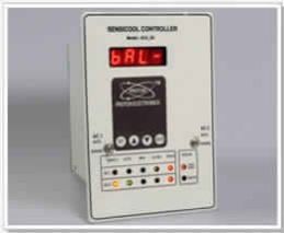
PROTON's PHASE CORRECTOR RELAY' offer following protections along with 3 digit display showing R-Y, Y-B, BR voltages in scanning mode with precise accuracy.
LOW/HIGH voltage tripping to ensure trouble free running of 3-phase Loads. Single phasing & Unbalance protection. Phase correction RELAY 'R2' which operates only when phase sequence changes.

Phase sequence failure or phase reversal in a three phase induction motor can be dangerous when the opposite direction not allow in certain applications like Non reversing gear box, Screw Compressors, Certain Specialized Pumps, Blower fan etc. In certain cases it hazards to operating personnel. Phase reversal in a motor feeder produces a negative sequence of nearly 100% and is well detected by a relay with negative sequence / Phase Reverse protection.

With growing shortage and escalating cost of Electrical Energy, accurate monitoring of Air Conditioner's parameters has become necessary. DAMPER CONTROLLER is most useful for controlling Dampers & A/Cs. This instrument is able to maintain Room Temperature with an accuracy of 0.1 degree C by automatic measurement of Room temperature, Outdoor temperature and accordingly controlling A/C & Damper ON/OFF.

VAF meter displays the Phase-Phase Voltages Phase - Neutral on the first row, Second row displays frequency & the Third row Displays the Ampere Value.

The 1 Phase Overload Relay is a solid state protection relay. It measures current and provides protection against overload, . This is based on a single chip micro controller, with a high degree of programmability. The Unit is supplied preprogrammed for operation and can be directly installed.It provides Voltage and current protection

1) Modbus RTU Protocol support over RS-485 Electrical Standard
2) GSM support
Supply Voltage: 230 VAC +- 15 %
Display : LCD 2x16 with Back light
Input :
1).Temp Sensors 3 Nos
b). Inlet Temperature.
c). water temperature.
d). ambient temperature.
2). Potential free input HP / LP for Compressor
3). Current input FROM CT for Pump
4). Potential free input for Dry Run (Flow)
nput :
1)Temp Sensors 3 Nos.
a) Inlet Temperature.
b) Water temperature.
c) Ambient temperature.
2)Potential free input HP / LP for Compressor
3)Current input FROM CT for Pump
4)Potential free input for Dry Run (Flow)
:


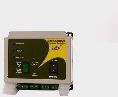
This wireless GSM remote controller helps the farmer to control agricultural pump sets easily. It also helps the farmer to irrigate the crops in proper schedule. Farmer can set the total running time of pumpset to be run. This saves water, time and electricity. GSM motor starter is a must device for farmers in today's world. This mobile starter protects the motor from low voltage, over voltage, dry Run, over Load.Some features are: Local language support, single phase preventer, auto starter , etc.
Primary cause of motor failure is excessive heating, which is sustained over long time periods will result in motor burn out. Overheating also reduces the life of motor. If a motor is continuously overheated by just 10 degrees, its life can get reduced by almost 50%. Overheating normally occurs due to Over Current, which in turn may be due to over load condition or low voltage or phase failure or phase unbalance.

This wireless GSM remote controller helps the farmer to control agricultural pump sets easily. It also helps the farmer to irrigate the crops in proper schedule. Farmer can set the total running time of pumpset to be run. This saves water, time and electricity. GSM motor starter is a must device for farmers in today's world. This mobile starter protects the motor from low voltage, over voltage, dry Run, over Load.Some features are: Local language support, single phase preventer, auto starter , etc.

This wireless GSM remote controller helps the farmer to control agricultural pump sets easily. It also helps the farmer to irrigate the crops in proper schedule. Farmer can set the total running time of pumpset to be run. This saves water, time and electricity. GSM motor starter is a must device for farmers in today's world. This mobile starter protects the motor from low voltage, over voltage, dry Run, over Load.Some features are: Local language support, single phase preventer, auto starter , etc.
Primary cause of motor failure is excessive heating, which is sustained over long time periods will result in motor burn out. Overheating also reduces the life of motor. If a motor is continuously overheated by just 10 degrees, its life can get reduced by almost 50%. Overheating normally occurs due to Over Current, which in turn may be due to over load condition or low voltage or phase failure or phase unbalance. Current unbalance in motor is best represented by the presence of excessive negative sequence components in the motor current. Consequently it is necessary to protect motors against negative sequence. Considering the above details, it can be easily concluded that a Motor Protection Unit (MPU) will provide an effective protection to the motor as it is equipped to measure the negative sequence component level in the motor feeder.

The RO Control cum Starter Panel is a Micro Controller based solid state compact unit. It measures Mains Voltage and Currents at Raw Water Pump (RWP) and High Pressure Pump (HPP). It provides Over and Under Voltage protection as well as Overload and Under Load (Dry Run) protection for both the pump motors. Voltage and Current protection settings are user settable with a password protection. Process interlocks like Low Pressure at HPP suction, High Pressure at HPP delivery and Product Tank Level High are pre-programmed for reliable operation of the plant. Controller also provides Flush Valve Solenoid and Dosing Pump power control. Low Pressure trip delay and Flush timings are settable. All the electrical trip delay timings are settable.