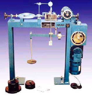
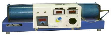
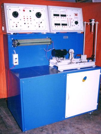
The wonderful range of Tribology Laboratory Equipment is accessible from us. We are available with the exclusive range of Tribology Laboratory Equipment which is of optimum quality. Tribology Laboratory Equipment is offered at such prices which are less than the other places. In addition, we are the market dominating Tribology Lab Equipment Manufacturer and Suppliers in India. TRB-01A INTRODUCTION EEE Journal Bearing Apparatus consists of a plain steel shaft encased in a bearing and directly driven by a small electric motor. The bearing is freely supported on the shaft and sealed at the motor end. The motor speed is precisely controlled and adjusted by specially designed control unit and can be run in both directions.The bearing contains twelve equispacedpressure tapings around its circumference and four additional ones along its topside and one vertical radial plane. All are connected by light and flexible plastic tubes to the rear manometer panel so that pressure head of oil at all sixteen points can be clearly observed at all times. Oil is supplied to a law pressure region at both ends of the bearings by an adjustable reservoir fitted at the side of the rear panel. The bearing can be loaded by attaching various weights to the arms supported beneath it. A table is conveniently provided at front of the apparatus. FEATURES 1. Acrylic Bearing Housing allows clear observation of the oil film at all ties2. Pressure profiles along and around the bearing continuously monitored on large manometer panel.3. Theoretical pressure profile (Sommerfeld Analysis) can be carried out and compared with practicalresults.4. Wide range of speed and loads possible.5. Ideal for group studies and demonstrations.6. DC motor is used with speed control unit.6. Digital pressure indicator- 1no. for pressure measurement for each tapping RANGE OF EXPERIMENTS 1. Simple Demonstrations2. Observation of the pressure profile at the various conditions of load and speedEXPERIMENTAL INVESTIGATION3. After noting the pressure profile for any chosen conditions, the following analysis may beconducted.4. Plotting the Cartesian and polar pressure curves.5. Plotting the theoretical Sommerfeld curves. -k sin (2+ncos)P-P = --------------------------- 0(1 + ncos) SPECIFICATIONS Journal : 50mm. (Nominal)Bearing : 55mm.Weights : 4 adjustable weights of 100 gm eachRecommended oil : SAE 10/40Motor : PMDC motor with , speed range 500-3000 rev/min in bothControl unit : 2 Amp. Closed type Dimmer.Pressure Sensor : Digital with -1 to +3 bar pressure range . INSTRUCTION MANUAL A manual is supplied which gives details of the apparatus and procedure of experiments along with sample calculations SERVICE REQUIRED
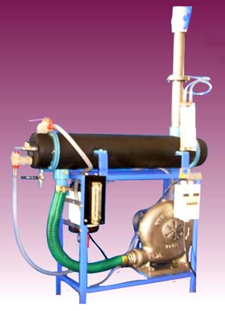
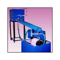
230V AC single phase electrical supply. 5A 50Hz. Floor space : 2m width X 1m length Approximately. TRB- 02 INTRODUCTION EEE Michell Tilting Pad Thrust BearingApparatus provides visual demonstration and measurement of longitudinal and transverse pressure distribution over Michell Thrust Bearing. It provides the study of Reynolds equation by varying speeds, velocity of oil and oil gap. It gives visual demonstration of cavitation. It consists of a belt moving on two equal pulleys driven by a D.C. variable speed motor. The belt dips in the oil tank and carries oil film along with it. This oil passes through tilting pads and develops pressure, which is measured by manometer through the tapings in traverse and longitudinal direction on the pad. Different types of pads can be mounted for the demonstration of hydrodynamic Film lubrication phenomenon of pressure development in this Tilting Pad Apparatus. RANGE OF EXPERIMENTS 1. Demonstration of pressure development(a) In Longitudinal direction of Tilting Pad(b) In Transverse Direction of Tilting Padon PC with the use of pressure sensor and interface unit .2. Plotting pressure variation curve in longitudinal & transverse direction of a pad for three speedsand pad inclination.3. Approximate comparison of theoretical and practical values possible. SPECIFICATIONS 1. Motor: H.P. 1500 rpm. PMDC motor with speed control.(solid state)2. Multi Tube Manometer: Height 1000 mm.Tubes : 9 tubes in longitudinal direction: 7 tubes in transverse direction.3. Manometer: Common header and tubs in longitudinal direction for cavitation Demonstration.4. Tilting Pads : Rectangular, Trapezoidal, Circular5. Oil Tank : 550 mm x 240 mm x 150 mm approximately6. Digital rpm indicator with proximity switch.7. Loading Arrangement on pad with springs and hand knob .8. Electronic pressure sensor with digital indicator having computer interface.9. Item no 2&3 are used for manual observation of pressure variation. INSTRUCTION MANUAL A manual is supplied which gives details of the apparatus and procedure of experiments along with sample calculations Educational software CD will provided with the equipment SERVICE REQUIRED 230V AC single phase electrical supply. 5A 50Hz. Floor space : 2m width X 1m length Approximately.