Listing ID #3829710
Company Information
Ask for more detail from the seller
Contact SupplierSalient Features
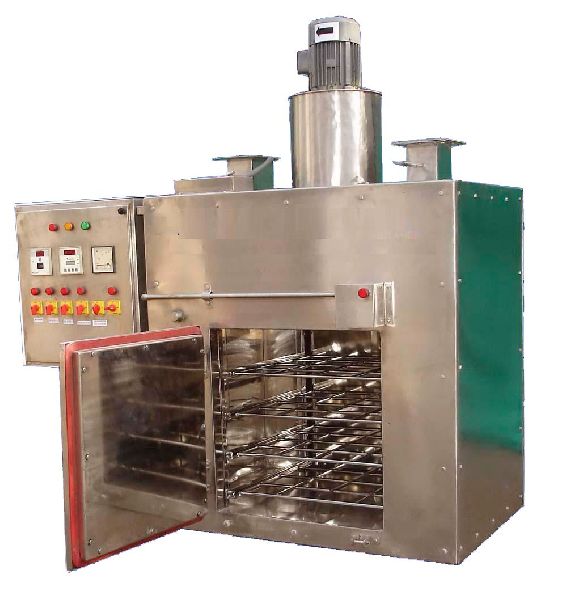
Process Operation
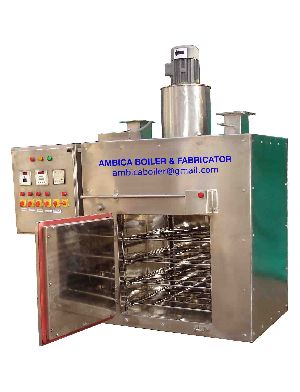
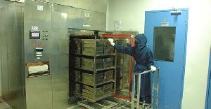
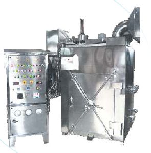
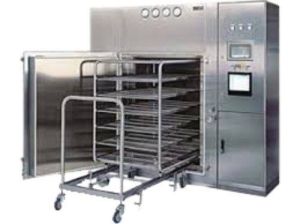
The Ampoules / Vials placed in trays are washed in non-sterile room and loaded on the trolley. The trolley is moved to the sterilizer on a transfer trolley. Temperature and Times are set on the Digital Controller. The Impeller mounted on the top circulates the hot air horizontally over the charge. The air is heated by elements mounted on the top. Fresh air enters the system through Hepa Filter Module. The system incorporates two doors, one opening into the sterile room and the other opening in the non-sterile room. Both the doors are pneumatically interlocked. The temperature profile during sterilization cycle is recorded on a circular chart recorder, validation of the system is provided by a six-point digital temperature scanner. After the time period required for sterilizing the batch has elapsed, the heating circuit shuts of the pneumatics damper (exhaust) opens and cooling operation commences.
| Temperature | Up to 250°C |
| Material of Construction | Interiors with 14 gauge S.S. 316 quality sheets. Exteriors with 16 gauge S.S. 304 Quality sheet. Frame work of Rolled steel sections 6, 5 & 3mm. the interior frame work of S.S 316 quality |
| Trolley | Fabricated from AISI SS 316 Quality angles & flats with ‘U’-Grooved Stainless Steel wheels. |
| Transfer trolley | Fabricated from S.S. 304 Quality Angles & flats with castor wheel for sterile & Non-sterile room. |
| Doors | Two Doors, one opening into the sterile room and the other into the Non-sterile room. The doors are lined with silicon rubber for sealing. The door in the sterile room is claded with 16 gauge AISI SS 304 sheet. |
| Interlocking | To maintain the barrier between the sterile and non-sterile room, both the doors are pneumatically interlocked. The pneumatic system consists of pneumatic Cylinders, solenoid valves and flow control valves. |
| Insulation | 125mm (t) Mineral Wool. A grade mineral wool insulation to optimize heat effectiveness and stop heat loses. |
| Air recirculation | A 2 H.P. 1440-RPM motor drives the impeller. Air enters the Chamber through perforations provided passes horizontally over the charge and is re-circulated. |
| HEPA Filter Module | Air entering the system is passed through a HEPA Filter Module consisting of a pre-filter up to 5 microns, a blower & a HEPA Filter up to 0.3 microns. The filtered air is fed to the impeller for circulating in the system. |
| Temperature Control & Timer | A combined Electronic Digital Controller & Timer is installed. ±2ºC., one probe centrally mounted. |
| Scanner | A six point Digital Scanner is incorporated, with facility of Hold & Scan at all six points. |
| Temperature Recorder | A, 1 point Circular Chart recorder is installed with chart Dia. 8” |
| Cooling Coils | Crimped Finned Tubes with headers, S.S. 304 Quality to speed up cooling cycle. |
| Panel Board | Consists of: Ammeters, Voltmeter, Voltmeter switch, HRC fuses & Circular chart Recorder |
| Control panel | Motor Starter, Contactors, Rotary Switches, Indicating lights for heating & Cooling cycle and phase indicating lights. |
| Exhaust damper | Controlled by solenoid valve and is opened during the initial heat-up, shuts off and re-opens during cooling cycle. |
| Fan | Dynamically balanced fan provided for hot air circulation to achieve uniform temperature |
| Finish | All stainless steel components buffed to matt finish. |


Connect with us