My ExportersIndia

For Buyer

For Seller

For Help

Lithotech Engineers LLP - Industrial Mixers

Our product range contains a wide range of Blending Machine and Blender Cum Roaster

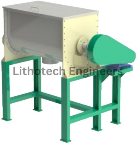
Blending Machine

1.40 Lakh - 2 Lakh / PieceGet Latest Price
  • Min. Order (MOQ)1 Piece
  • Brand NameLithotech Engineers LLP
  • Driven TypeElectric
  • ConditionNew
  • Automatic GradeAutomatic
  • ApplicationBlending
  • Country of OriginIndia
  • MaterialStainless Steel

Lithotech Ribbon Blender comprises of U-shaped container, transmission parts and ribbon agitating blades which usually have double or triple layers with outside screw gathering the material from sides to center and inside screw transmitting the material from center to sides to form convection mix.

Ribbon Blender has a good result in the mix of viscosity or cohesion powder and of putting liquid and mash material into the powder. The cylinder cover can be fully open so as to clean and change the device.

Technical Specification

ModelFRB-125FRB-250FRB-500FRB-750FRB-1000FRB-2500FRB-4000
Volume125 L250 L500 L750 L1000 L2500 L4000L
Capacity(Chilly/ Coriander Power)5010020030050010002000
View Complete Details
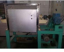
Blender Cum Roaster

    Blender Cum Roaster

    • Min. Order (MOQ)1 Piece
    • Driven TypeElectric
    • Automatic GradeAutomatic
    • Country of Origin220V
    • Country of OriginIndia
    • MaterialStainless Steel

    The complete drying plant compromises Rotary Cascade Dryer, Air Heater, Dryer Inlet Hood, Exhaust Hood, Exhaust Air Fan & Ducting and all necessary Controls.

    • Duty : To Dry about 750 Kg/hr. of Chilly Flakes from approximately 20% initial moisture to 8-10 % final moisture.
    • Dryer Drum: 3 Ft Diameter X 28 Ft. long dryer drum fabricated in Stainless Steel plate SS-304, with internal flights and lifters fabricated and bolted to Stainless steel angle sections welded to the shell plates to ensure adequate contact between the drying air and the material being processed. The drum is fitted with two cast or forged steel tires, mounted on carbon steel spacer blocks fitted to a reinforcing band. The tires run on four cast or forged steel support rollers shrunk to fit on steel shafts with shaft-mounted spherical roller bearing Plummer blocks. A segmental cast steel chain ring is fitted around the periphery of the dryer drum.
    • Support Frames : The complete dryer drum assembly is supported on two fabricated carbon steel roller support frames, the feed ends support frame carrying the locating roller assemblies. Both roller support frames are fitter with safety guards.
    • Drum Drive : The dryer drum is driven by a T.E.F.C. electric motor through a V-belt drive, gearbox, pinion, and chain to the drum drive chain wheel. The motor, gearbox, V-belt, etc. are mounted on a fabricated carbon steel baseplate. All drives are completely enclosed in suitable safety guards.
    • Air Heater : The drying air is provided using Electrical Operated, firing into a refractory lined carbon steel combustion chamber connected to the dryer inlet end hood. It can also be operated with an Electrical Heater of 30 KiloWatts rating.
    • Inlet End Hood : The inlet end of the drum is enclosed with a Stainless steel fabricated enclosure, complete with a labyrinth seal and stainless steel material inlet chute. The inlet hood is supported by a suitable rolled steel section support structure.
    • Outer End Hood: The outer end of the drum is enclosed with a carbon steel fabricated hood complete with an inspection access door, and exhaust air outlet chute. A labyrinth-type flexible seal is fitted to the rear hood plates around the drum opening. The outlet end is supported by a suitable rolled steel section support structure.
    • Exhaust Air Fan : The exhaust air is drawn from the dryer by a centrifugal fan, complete with an electric motor, V-belt drive, and drive guard.
    • Exhaust Air Ducting : The exhaust air from the dryer is conveyed via a Stainless steel duct from the outlet end hood to the cyclone and from the cyclone to the exhaust fan. A manually operated butterfly-type valve damper is fitted in the exhaust duct between the cyclone and the exhaust fan.
    • Control System : Inlet air temperature is measured using a thermocouple located in the inlet end hood connected to a temperature indicator/recorder. Exhaust air temperature is measured by a thermocouple located in the exhaust air duct connected to a temperature indicator/recorder. The Electrical output is controlled using a suitable Thermostat via a suitable transmitter from either of the two temperature indicator controllers. All necessary motor control gear, relays, overloads, etc. and temperature indicators/recorders are housed in a carbon steel control cabinet which will be prewired for correct sequential start-up and operation of the plant.
    View Complete Details
    Tell Us What are you looking for? Will call you back

    Contact Us