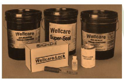
Our Products
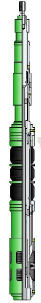
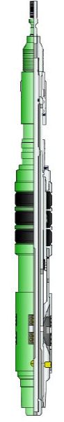
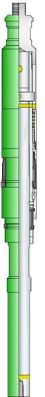
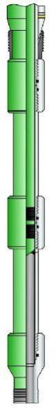
We offer a complete product range of Mill-Out Bottom, Snap Latch Assembly, WC-MECH-6 Hydraulic Compression Snap Set Packer with & Without Hold Down, Seal Bore Extension and Typical Hook-Up Of Seal Bore Packer With Millout Extension And Seal Bore Extension

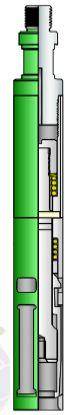
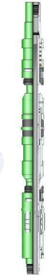
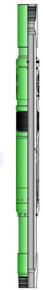
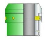
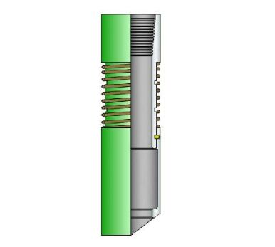
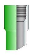
Snap Set Compression Packer with & without hold down are retrievableset down packers featuring a bypass area through the packer and anintegral unloaded. They are used as an upper packer in a single stringtwo packer installation, for zone isolation, injection or production.Packers are used above either retainer production packers or retrievablepackers.
Benefits :
Applications :
Specification Guide
| Casing | Packer | ||||||
| SIZE | Weight | Min. ID | Max. ID | Max. OD | Min. ID | End Connection |
|
| inch mm | Lb/ft | inch mm | inch mm | inch mm | inch mm | inch | |
| 5 1/2 | 14-20 | 4.778 | 5.012 | 4.5 | 1.93 | 2 3/8 EU 8RD | |
| 139.7 | 121.36 | 127.3 | 114.3 | 50.3 | |||
| 7 | 20-26 | 6.276 | 6.456 | 5.875 | 2.875 | 2 7/8 EU 8RD | |
| 177.8 | 159.41 | 163.98 | 149.22 | 73.02 | |||
| 9 5/8 | 43.5-53.5 | 8.535 | 8.755 | 8.250 | 2.990 | 3 1/2 8 EU | |
| 244.4 | 216.78 | 222.37 | 209.55 | 75.94 | 8RD | ||

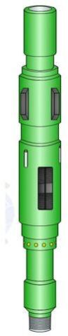
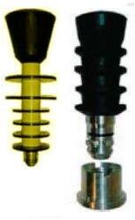
These are field-proven modular designed high performance drillable bridge plugs, commonly used for zonal isolation during stimulation or cementing jobs, or for temporary and permanent abandonments. This can easily be converted to a Cement Retainer. A modified version of this Bridge Plug is available for use primarily in gas well applications. Simple design allows the upper portion of the body and the bridging plug to be drilled out, generating pressure equalization across the tool before drilling out the upper slips. Changing the upper slip enable the bridge plug to be set mechanically or on a wireline setting tool assembly. It is easily converted to a cement retainer.
Features/Benefits :
Applications :
Features/Benefits :
Application :
Technical Specification
| Casing | Bridge Plug | |||
|---|---|---|---|---|
| Size | Weight Lb / Ft | Min Id | Max Id | Max Od |
| 3-1/2 | 10.2 | 2.992 | 2.992 | 2.781 |
| 3-1/2 | 7.7-9.2 | 2.992 | 3.068 | 2.867 |
| 4-1/2 | 9.5-13.5 | 3.91 | 4.09 | 3.771 |
| 5 | 15.0-18.0 | 4.25 | 4.408 | 4.125 |
| 5 | 11.5-15.0 | 4.408 | 4.56 | 4.25 |
| 5-1/2 | 26 | 4.408 | 4.56 | 4.25 |
| 5-1/2 | 20.0-23.0 | 4.625 | 4.778 | 4.5 |
| 5-1/2 | 15.5-20.0 | 4.778 | 4.95 | 4.641 |
| 5-1/2 | 13.5-15.5 | 4.95 | 5.19 | 4.781 |
| 6 | 26 | 4.95 | 5.19 | 4.781 |
| 6-5/8 | 24.0-32.0 | 5.61 | 5.921 | 5.484 |
| 6-5/8 | 24 | 5.83 | 5.937 | 5.656 |
| 7 | 38 | 5.83 | 5.937 | 5.656 |
| 6-5/8 | 17.0-20.0 | 5.938 | 6.135 | 5.812 |
| 7 | 32.0-35 | 5.938 | 6.135 | 5.812 |
| 7 | 26.0-29.0 | 6.136 | 6.276 | 5.968 |
| 7 | 23.0-26.0 | 6.276 | 6.366 | 6.078 |
| 7 | 17.0-20.0 | 6.456 | 6.578 | 6.266 |
| 7-5/8 | 33.7-39.0 | 6.579 | 6.797 | 6.453 |
| 7-5/8 | 24.0-29.7 | 6.798 | 7.025 | 6.672 |
| 7-5/8 | 20.0-28.0 | 7.025 | 7.125 | 6.812 |
| 8-5/8 | 20.0-28.0 | 8.017 | 8.097 | 7.781 |
| 9-5/8 | 47.0-53.5 | 8.343 | 8.681 | 8.218 |
| 9-5/8 | 40.0-47.0 | 8.681 | 8.835 | 8.437 |
| 9-5/8 | 29.3-36.0 | 8.836 | 9.063 | 8.593 |
Features/Benefits : The Model WC-SSB Snap Latch Stinger Sub is used with Model WCWMCR Wireline Set Cement Retainers. It features a snap-in, snap-outtype latch that provides a surface indication of the stinger being landed in the cement retainer (giving assurance that the sleeve valve is open) or the stinger sub being removed from the cement retainer (and the sleeve valve closed).
Application : The Model WC-CU Control Unit is made up above the stinger sub and provides a centering device for entering the retainer bore.
Technical Specification
| Size | X1-Y2 | X3-X9 | X11-X11 |
|---|---|---|---|
| End Conncection | 2 3/8 Eu 8 Rd | 2 7/8 Eu 8 Rd | 3 1/2 Eu 8 Rd |

The Snap Latch Setting Tool is a mechanical setting tool used to set the Bridge Plugs and Cement Retainers. It possess a built-in snap-latch feature which allows the setting tool to be latched to the product with set-down weight and released with up strain and rotation after setting the product. This essentially allows the setting tool to function as a snap latch stinger sub which provides an upward stop as the tubing is raised. At this stop the valve is closed but the stinger sub seal is still in the bore of the retainer. At this position in the running string internal pressure test could be carried out.
WELLCARE Separation Sleeve, when attached to an appropriate lock is a wire-line retrievable tool, used to isolate the control line port of Safety Valve Landing Nipples.

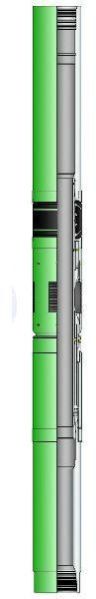
The Liner Tieback Packer is a liner top packer that is most frequently run on drill pipe using a mechanical setting tool and a tie back receptacle liner setting sleeve with tieback extension. The packer is run to the top of an existing liner tieback extension, and the seal stem is inserted until seated and pressure tested down the drill pipe. Additional set-down weight shears the release pins and sets the packer seal. The setting tool is released with right hand rotation. The tieback stem on the Tieback Packer has three sets of glass-filled Teflon Chevron seals for severe pressure and temperature applications. It features ratchet lock in the setting shoulder to prevent premature setting while running in. Maximum seal integrity is assured by a threepiece rubber sealing element contained by metal back-up rings. Hold down slips and an internal body-lock ring maintains seal compression and prevents floating of short liners. The Tieback Packer can be released by cutting the inside mandrel in the designated area. Tieback receptacles are available with this packer in different lengths e.g.: 6 ft, 10 ft, 15 ft, 20 ft etc as per requirements or demand from customers. Available in rotating or non-rotating configuration with retrievable or no cementing bushing profile running and setting, this assembly may be configured with conventional mechanical right hand release running tool, rotating mechanical running tool or hydraulic release running tool. The packer is furnished with higher group of API 5CT standard materials as well as with the end connection in compliance to API standards or any premium threads as per the customer’s requirement/demand. CRA materials suited for H2S or CO2 service are available on request.
Features / Benefits :

Conductor Pipe Centralizer are being used in Oil Well Rig in big well bore. These centralizers are very heavy duty centralizer. These are available with us for different hole size varying from 20 ”to 30” for respective casing sizes.
Features :
Technical Specifications
| Casing Size in | Hole Size in | Nos. Of Bows | OD In |
|||||||||
|---|---|---|---|---|---|---|---|---|---|---|---|---|
| 2 – 7 / 8 | 4 – 1 / 8 | 4 | 3 – 49 / 64 | |||||||||
| 6, 6 – 1 / 8 | 4 | 5 – 41 / 64 | ||||||||||
| 3 – 1 / 2 | 6 – 1 / 8 | 4 | 5 – 41 / 64 | |||||||||
| 4 | 6 – 1 / 8 | 4 | 5 – 41 / 64 | |||||||||
| 4 – 1 / 2 | 6 | 4 | 5 – 3 / 4 | |||||||||
| 6 – 1 / 4 | 4 | 6 | ||||||||||
| 6 – 1 / 2 | 4 | 6 – 1 / 4 | ||||||||||
| 7 – 7 / 8 | 4 | 7 – 5 / 8 | ||||||||||
| 5 | 6 – 1 / 2 | 4 | 6 – 1 / 4 | |||||||||
| 6 – 3 / 4 | 4 | 6 – 1 / 2 | ||||||||||
| 7 – 7 / 8 | 4 | 7 – 5 / 8 | ||||||||||
| 8 – 1 / 2 | 4 | 8 – 1 / 4 | ||||||||||
| 5 – 1 / 2 | 6 – 3 / 4 | 4 | 6 – 1 / 2 | |||||||||
| 7 – 7 / 8 | 4 | 7 – 5 / 8 | ||||||||||
| 8 – 1 / 2 | 4 | 8 – 1 / 4 | ||||||||||
| 8 – 3 / 4 | 4 | 8 – 1 / 2 | ||||||||||
| 6 – 5 / 8 | 8 – 1 / 2 | 5 | 8 – 1 / 4 | |||||||||
| 7 | 8 – 1 / 2 | 5 | 8 – 1 / 4 | |||||||||
| 8 – 3 / 4 | 5 | 8 – 1 / 2 | ||||||||||
| 9 – 7 / 8 | 5 | 9 – 5 / 8 | ||||||||||
| 7 – 5 / 8 | 9 – 7 / 8 | 5 | 9 – 5 / 8 | |||||||||
| 8 – 5 / 8 | 10 – 5 / 8 | 6 | 10 – 3 / 8 | |||||||||
| 11 – 5 / 8 | 6 | 11 – 3 / 8 | ||||||||||
| 12 – 1 / 4 | 6 | 12 | ||||||||||
| 9 – 5 / 8 | 11 – 5 / 8 | 6 | 11 – 3 / 8 | |||||||||
| 12 – 1 / 4 | 6 | 12 | ||||||||||
| 13 – 3 / 4 | 6 | 13 – 1 / 2 | ||||||||||
| 9 – 7 / 8 | 11 – 5 / 8 | 6 | 11 – 3 / 8 | |||||||||
| 12 – 1 / 4 | 6 | 12 | ||||||||||
| 13 – 3 / 4 | 6 | 13 – 1 / 2 | ||||||||||
| 10 – 3 / 4 | 12 – 1 / 4 | 6 | 12 | |||||||||
| 13 – 3 / 4 | 6 | 13 – 1 / 2 | ||||||||||
| 14 – 3 / 4 | 6 | 14 – 1 / 2 | ||||||||||
| 11 – 3 / 4 | 13 – 3 / 4 | 7 | 13 – 1 / 2 | |||||||||
| 14 – 3 / 4 | 7 | 14 – 1 / 2 | ||||||||||
| 15 – 1 / 2 | 7 | 15 – 1 / 4 | ||||||||||
| 13 – 3 / 8 | 16 | 8 | 15 – 3 / 4 | |||||||||
| 17 – 1 / 2 | 8 | 17 – 1 / 4 | ||||||||||
| 13 – 5 / 8 | 16 | 8 | 15 – 3 / 4 | |||||||||
| 17 – 1 / 2 | 8 | 17 – 1 / 4 | ||||||||||
| 14 | 16 | 8 | 15 – 3 / 4 | |||||||||
| 17 – 1 / 2 | 8 | 17 – 1 / 4 | ||||||||||
| 16 | 20 | 10 | 19 – 3 / 4 | |||||||||
| 22 | 10 | 21 – 3 / 4 | ||||||||||
| 18 – 5 / 8 | 22 | 10 | 21 – 3 / 4 | |||||||||
| 24 | 10 | 23 – 3 / 4 | ||||||||||
| 20 | 24 | 10 | 23 – 3 / 4 | |||||||||
| 26 | 10 | 25 – 3 / 4 | ||||||||||

Consists of a hinged collar radiating into bristles. Each bristle is made of hardened & tempered wire with two scratching elements. Available in the size range 4 ½ ” to 20” these scratchers improve the cement bond between the casing and porous formations while reinforcing the cement column.
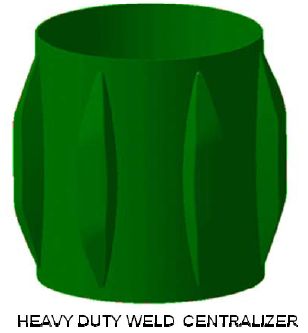
WELLCARE Heavy Duty Welded Centralizers are high quality welded product which meets the specification. These centralizers have boat type bows which are strongly welded to the end collars/pipe under the required temperature conditions with correct grade electrode. These centralizers are made in variety of style, but they generally have straight or curved vanes. They can be secured to the casing OD, or they can float between casing stop collars if the well casing is to be rotated during cementing. Reduce friction between the casing and the hole, allowing the casing to be inserted more easily into the wellbore.
The straight-vane rigid centralizer is used during operations in which casing centralization is a primary objective. The centralizer can be attached to the casing with set screws located between each vane, preventing casing rotation or reciprocation during cementing operations. If the casing will be rotated or reciprocated during cementing operations, the centralizer can float on the casing joint between the stop rings. A flexible ceramic coating can be applied to the entire turbulator to reduce friction. Th e rigid centralizer is normally 10" long, but it can be manufactured to any length as per the customer requirement. The vane ODs are typically ¼" less than the bit size used to drill the well.
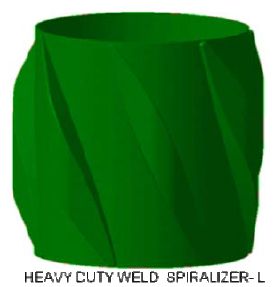
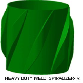
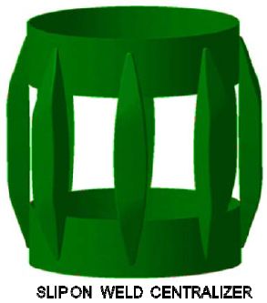
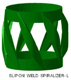
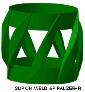
WELLCARE Slip –On Welded Spiralizer are high quality welded product which meet the specifications. The centralizers have bow springs strongly welded to the end collars under required temperature conditions with correct grade electrode. The end collars are available in latch-on design with high strength steel. These centralizers have boat type bow, strongly welded to the end slip on collars under required temperature conditions with correct grade electrode. These centralizers are made in a variety of style, but they generally have straight or curved vanes. They can be secured to the casing OD, or they can float between casing stop collars if the well casing rotates during cementing. Spiralizers are available in spiral and straight blades which resist high side loads. While giving maximum standoff these blades create vortex flow to optimize mud displacement.
Technical Specifications
| Casing Size in | Hole Size in | Nos. of Bows | Maximum OD in | |
|---|---|---|---|---|
| 4 – 1 / 2 | 6 | 4 | 5 – 3 / 4 | |
| 6 – 1 / 4 | 4 | 6 | ||
| 6 – 1 / 2 | 4 | 6 – 1 / 4 | ||
| 7 – 7 / 8 | 4 | 7 – 5 / 8 | ||
| 5 | 6 – 1 / 2 | 4 | 6 – 1 / 4 | |
| 6 – 3 / 4 | 4 | 6 – 1 / 2 | ||
| 7 – 7 / 8 | 4 | 7 – 5 / 8 | ||
| 8 – 1 / 2 | 4 | 8 – 1 / 4 | ||
| 5 – 1 / 2 | 7 – 7 / 8 | 4 | 7 – 1 / 2 | |
| 8 – 1 / 2 | 4 | 8 – 1 / 8 | ||
| 8 – 3 / 4 | 4 | 8 – 1 / 4 | ||
| 9 – 7 / 8 | 4 | 8 – 1 / 2 | ||
| 6 – 5 / 8 | 8 – 1 / 2 | 4 | 8 – 1 / 8 | |
| 7 | 8 – 1 / 2 | 4 | 8 – 1 / 4 | |
| 8 – 3 / 4 | 4 | 8 – 1 / 2 | ||
| 9 – 7 / 8 | 4 | 9.5 / 8 | ||
| 7 – 5 / 8 | 9 – 7 / 8 | 4 | 9.5 / 8 | |
| 8 – 5 / 8 | 10 – 5 / 8 | 6 | 10 – 3 / 8 | |
| 11 – 5 / 8 | 6 | 11 – 3 / 8 | ||
| 12 – 1 / 4 | 6 | 12 | ||
| 9 – 5 / 8 | 11 – 5 / 8 | 6 | 11 – 3 / 8 | |
| 12 – 1 / 4 | 6 | 12 | ||
| 13 – 3 / 4 | 6 | 13 – 1 / 2 | ||
| 9 – 7 / 8 | 11 – 5 / 8 | 6 | 11 – 3 / 8 | |
| 12 – 1 / 4 | 6 | 12 | ||
| 13 – 3 / 4 | 6 | 13 – 1 / 2 | ||
| 10 – 3 / 4 | 12 – 1 / 4 | 6 | 12 | |
| 13 – 3 / 4 | 6 | 13 – 1 / 2 | ||
| 14 – 3 / 4 | 6 | 14 – 1 / 2 | ||
| 11 – 3 /4 | 13 – 3 / 4 | 8 | 13 – 1 / 2 | |
| 14 – 3 / 4 | 8 | 14-1/2 | ||
| 15 – 1 / 2 | 8 | 15-1/4 | ||
| 13-3/8 | 16 | 8 | 15-3/4 | |
| 17-1/2 | 8 | 17-1/4 | ||
| 13-5/8 | 16 | 8 | 15-3/4 | |
| 17-1/2 | 8 | 17-1/4 | ||
| 14 | 16 | 8 | 15-3/4 | |
| 17-1/2 | 8 | 17-1/4 | ||
| 16 | 20 | 10 | 19-3/4 | |
| 22 | 10 | 21-3/4 | ||
| 18-5/8 | 22 | 10 | 21-3/4 | |
| 24 | 10 | 23-3/4 | ||
| 20 | 24 | 10 | 23-3/4 | |
| 26 | 10 | 25-3/4 | ||

The Wellcare Impression Block is an accessory tool used to accurately determine the dimensions and configuration of the upper end of a fishing item as well as to check its condition and position in the well bore. The soft lead lower end of the impression block captures an impression of the fish upon making contact. Impression blocks are manufactured with a connection (pin up) and a layer of soft lead on the lower end of the tool. Circulation holes will be provided on request. End connection is furnished as per customer requirement.
Assembly and Operation : Make up the impression block to the bottom of the fishing string. Run into hole until impression block is near top of fish. Slowly lower pipe until making contact with fish. Do not rotate. Apply weight to impression block and then pull out of hole. The impression made will assist the operator in determining what tools are needed to prepare and retrieve the fish.
Technical Specifications
| Od In | Length In |
|---|---|
| 1 5/8 | 12 |
| 2 1/4 | 12 |
| 2 3/4 | 12 |
| 4 3/4 | 15 |
| 5 1/2 | 15 |
| 5 3/4 | 15 |
| 8 | 19 |
| 8 ½ | 19 |
| 11 | 20 |
| 11 1/2 | 20 |
| 11 3/4 | 20 |
| 12 | 20 |

The Model : WC-GS Pulling Tool is a wireline service tool designed to retrieve flow control devices from well bore. Pulling Tool is designed to engage an internal type fishing neck. The tool is available in a wide range of sizes for standard, H2S or CO2 service well conditions. The Pulling Tool is designed to be released from the down-hole device by downward jarring.

‘A’ shank is used with the ‘C1’ running tool to run lock mandrels into the well (keeping dogs retracted during running in). It can also be used as a probe carrier when probes are required during running in operations.
Technical Specifications
| Shank Size | Accessory Size | Shank Length | ||
| Standard Locks | No-Go Locks | |||
| Dogs Trailing | Dogs Retracted | Dogs Trailing | ||
| in | in | in | in | in |
| 2 – 1 / 16 | 1.43 | 4 3/4 | 5 7/8 | 4 |
| 1.5 | ||||
| 1.56 | ||||
| 1.62 | ||||
| 2.3/8 | 1.78 | 5 | 6 1/8 | 4 |
| 1.81 | ||||
| 1.87 | ||||
| 2.7/8 | 2.06 | |||
| 2.25 | 4 11/16 | 6 3 /32 | 4 | |
| 2.31 | ||||
| 3.1/2 | 2.56 | |||
| 2.75 | 5 5/16 | 6 11/16 | 4 | |
| 2.81 | ||||
| 4.1/2 | 3.68 | 7 | 6 1/2 | 4.75 |
| 3.75 | ||||
| 3.81 | ||||

The model ‘WC-C1’ running tool runs flow Control devices into the well those have external fishing neck locks. A thread protector, which has the same OD as the tool body, makes selective setting possible. A seal bore locating ring provides Top No go setting. The ‘C1’ running tool has box-down connection to make up with ‘A’ or ‘N1’ type shanks as required.
Technical Specifications
| Tubing Size | Nipple Seal Bore Size | Accessory Size in | Running Tool Size | Locating Ring Size | Top Thread Connection | Fish Neck Size | Shear Pin Diameter |
|---|---|---|---|---|---|---|---|
| in | in | in | OD in | Size in | OD in | OD in | |
| 2 – 1 / 16 | 1.562 | 1.56 | 2 – 1 / 16 | 1.593 | 15/16-10 | 1.188 | 1/8 |
| 1.625 | 1.62 | 1.656 | |||||
|
2 3 / 8 |
1.781 | 1.78 | 2 3 / 8 | 1.807 | 15/16-10 |
1.375 |
3/16 |
| 1.812 | 1.81 | 1.843 | |||||
| 1.875 | 1.87 | 1.906 | |||||
| 2 7/8 | 2.062 | 2.06 | 2.093 | ||||
| 2.25 | 2.25 | 2 7/8 | 2.281 | 15/16-10 | 1.75 | 3/16 | |
| 2.312 | 2.31 | 2.343 | |||||
| 3 1 /2 | 2.562 | 2.56 | 2.593 | ||||
| 2.75 | 2.75 | 3.1/2 | 2.781 | 1 1/16-10 | 2.312 | 3/16 | |
| 2.812 | 2.81 | 2.843 | |||||
| 4 1/2 | 3.688 | 3.68 | 4 1/2 | 3.718 | 1 1/16-10 | 3.125 | 3/16 |
| 3.75 | 3.75 | 3.802 | |||||
| 3.812 | 3.81 | 3.835 |

It is designed for use with conventional land based drilling and service rigs, as well as with offshore rigs not equipped with a top drive or using a conventional manifold. The heavy duty design and construction of this assembly easily handles the tensile loads seen in deep drilling liner applications with sufficient capacity to handle any problems like stuck pipe that could occur while running a liner assembly. Cementing Manifold is a robust cementation device which allows you to hang drill pipe weight by the rig elevators meanwhile retaining the plug to be released at will, once cementing is complete. The Cementing Manifold also connects the cementing lines to the running string during liner operations, and includes a heavy duty swivel for easy drill pipe string manipulation with the cementing lines still connected to the manifold. The swivel mechanism and drill pipe plug retainer are built in below the elevators for unobstructed operation. Cementing Manifold is available with single or multi plug drop capabilities.
Features and Benefits :

WELLCARE manufactures spiral blade solid spiralizers. These are made of one piece high grade corrosion resistant cast iron, aluminum alloy and non sparking metal-zinc alloy. They are high impact and shock resistant, possess high tensile and yield strengths and are wellhead friendly. They provide maximum casing or wellbore standoff, the prime requisite of an excellent primary cement job. This is irrespective of lateral loads.The straight blades are self cleaning in nature and designed to enhance flow. They endure steep temperatures in the wellbore, friction factor is minimum, with reduced drag and torque, ensuring maximum fluid passage.Spiralizers provide the almost wall contact and fluid swirl. They give optimum flow area in highly deviated and horizontal wells. The casing effectively reaches TD due to the sloping rare ends reducing drag. The slope also ensures that no balling between the vanes takes place, as scraping, gouging or digging into the formation is eliminated. WELLCARE Spiralizers are developed in response to the need for better cementing in highly deviated and horizontal wells. These are designed to provide optimum flow area. The 360 degrees over lapping solid vane provide maximum wall contact and fluid swirl. Reduced flow area between the spiral blades produces a vortex motion of the fluids for more fluid velocity with direction. These are made of high strength corrosion resistant cast aluminum and also non-sparking zinc alloy. The 30 deg. slope of the vane end reduce drag and aids the casing in reaching TD. This gentle flow from the body to the height of the vane will eliminate scraping, gouging or digging into the formation and consequently reduce balling between the vanes. They also posses high impact and shock resistance combined with tensile and yield strength as well as resists corrosion.

WELLCARE SlipOn Welded Spiralizers and centralizers are high quality welded product which meet the specifications. These have boat type bows which are welded with the end collars in controlled temperature conditions making use of correct grade electrodes. The end collars are available in slip-on design with high strength steel. These centralizers have boat type bow, strongly welded to the end slip on collars under required temperature conditions with correct grade electrodes. These are made in a variety of catagories, such as straight or curved vanes with right or left orienation. They can be secured to the casing OD, or they can float between casing stop collars if the well casing rotates during cementing. These are available in spiral and straight blades which resist high side loads. While giving maximum standoff these blades create vortex flow to optimize mud displacement. These are available in sizes raging from 2-7/8 up to 20 casing sizes with the combination of hole sizes as shown in specification guide.
Technical Specification
| Casing Size in | Hole Size in | No. of Bows | Maximum OD Inches |
| 4 – 1 / 2 | 6 | 4 | 5 – 3 / 4 |
| 6 – 1 / 4 | 4 | 6 | |
| 6 – 1 / 2 | 4 | 6 – 1 / 4 | |
| 7 – 7 / 8 | 4 | 7 – 5 / 8 | |
| 5 | 6 – 1 / 2 | 4 | 6 – 1 / 4 |
| 6 – 3 / 4 | 4 | 6 – 1 / 2 | |
| 7 – 7 / 8 | 4 | 7 – 5 / 8 | |
| 8 – 1 / 2 | 4 | 8 – 1 / 4 | |
| 5 – 1 / 2 | 7 – 7 / 8 | 4 | 7 – 1 / 2 |
| 8 – 1 / 2 | 4 | 8 – 1 / 8 | |
| 8 – 3 / 4 | 4 | 8 – 1 / 4 | |
| 9 – 7 / 8 | 4 | 8 – 1 / 2 | |
| 6 – 5 / 8 | 8 – 1 / 2 | 4 | 8 – 1 / 8 |
| 7 | 8 – 1 / 2 | 4 | 8 – 1 / 4 |
| 8 – 3 / 4 | 4 | 8 – 1 / 2 | |
| 9 – 7 / 8 | 4 | 9.5 / 8 | |
| 7 – 5 / 8 | 9 – 7 / 8 | 4 | 9.5 / 8 |
| 8 – 5 / 8 | 10 – 5 / 8 | 6 | 10 – 3 / 8 |
| 11 – 5 / 8 | 6 | 11 – 3 / 8 | |
| 12 – 1 / 4 | 6 | 12 | |
| 9 – 5 / 8 | 11 – 5 / 8 | 6 | 11 – 3 / 8 |
| 12 – 1 / 4 | 6 | 12 | |
| 13 – 3 / 4 | 6 | 13 – 1 / 2 | |
| 9 – 7 / 8 | 11 – 5 / 8 | 6 | 11 – 3 / 8 |
| 12 – 1 / 4 | 6 | 12 | |
| 13 – 3 / 4 | 6 | 13 – 1 / 2 | |
| 10 – 3 / 4 | 12 – 1 / 4 | 6 | 12 |
| 13 – 3 / 4 | 6 | 13 – 1 / 2 | |
| 14 – 3 / 4 | 6 | 14 – 1 / 2 | |
| 11 – 3 /4 | 13 – 3 / 4 | 8 | 13 – 1 / 2 |
| 14 – 3 / 4 | 8 | 14 1/2 | |
| 15 – 1 / 2 | 8 | 15 1/4 | |
| 13 3/8 | 16 | 8 | 15 3/4 |
| 37273 | 8 | 17 1/4 | |
| 13 5/8 | 16 | 8 | 15 3/4 |
| 37273 | 8 | 17 1/4 | |
| 14 | 16 | 8 | 15 3/4 |
| 37273 | 8 | 17 1/4 | |
| 16 | 20 | 10 | 19 3/4 |
| 22 | 10 | 21 3/4 | |
| 18 5/8 | 22 | 10 | 21 3/4 |
| 24 | 10 | 23 3/4 | |
| 20 | 24 | 10 | 23 3/4 |
| 26 | 10 | 25 3/4 |

Application:
The Model WC-CU Control Unit is made up above the stinger sub and provides a centering device for entering the retainer bore.

This retrieving tool is used to retrieve wireline set retrievable bridge plugs by running sufficient weight above the jars to prevent premature tool release when unloading pressure from below. If high differential pressure from below is expected, retrieval should done thru tubing or drill pile string. An Emergency Release is also provided for use when retrieving the tool on sand line or wireline in the event the tool will not release in the normal manner. Continued upward jarring will shear 50, 000 lb Shear sub and allow retrieval of the tool string and retrieving head.
Technical Specification
| Size Inch mm | OD Inch mm | Length Inch mm | End Connection Specification |
| 4 1/2 114.30 | 3.750 95.3 | 24.75 268.7 | 2 3/8 EU 8 RD |
| 5 127.00 | |||
| 5 1/2 139.70 | 4.5000 114.3 | 28.25 717.6 | 2 7/8 EU 8 RD |
| 7 177.8 | 5.500 139.7 | 30.12 765.1 | |
| 8 5/8 139.70 | 7.000 177.8 | 34.75 882.7 | 3 1/2 EU 8 RD |
| 9 5/8 244.5 | 8.200 208.3 |

This Separation Sleeve is a Top No-Go device which is run on wireline and designed to be landed and set in the L Type sliding sleeve. These are equipped with two packing assemblies those seal the upper and lower seal bore of sliding sleeve, therefore isolating the sleeve ports. Production can be maintained by producing the well through the inside diameter of the tool. The separation Sleeve is also designed with an internal equalizing plug to equalize pressure before retrieving.

HPL-2 Isolation Packer is a hydraulic set, single string tandem packer used in multiple zone wells. It is used as the upper packer in multiple zone applications.Isolation Packer run above another hydraulic retrievable packer to isolate a zone between them for treatment, injection, or production. The field-proven isolation packer can also isolate casing holes or perforations. The simple design and straight tubing-pull release make the packer a cost-effective tool to isolate zones in low-pressure applications.
Features/Benefits:
Economical Design
The straight-pull, shear-release pins are unaffected by differential pressure, enabling easy changes to the release force before running.
The compact design eases passage through doglegs and deviated wells to help prevent sticking and improve running efficiency.
The hydraulic setting avoids the need to rotate the work string in running or retrieving the packer, which simplifies procedures, improves efficiency, and saves rig time.
Application:
Low-pressure wells.
Stacked applications.
Applications prohibiting tubing rotation.
Isolation of casing holes and perforations.

these are hydraulic set permanent drillable packers. They have anenlarged seal bore to accept seal assemblies. In double bore the packerhas an upper larger seal bore for anchor tools or seal accessories to belatched and sealed.the range and combination of bore sizes are designed such that all theaccessories are commonly used for both the series of packers.a large bore version of single bore packer [model: wc-hsddpl] aremade in sizes so as to use the same range of accessories of abovepackers. They have a lower pressure rating because of the increasedbore size.the hydraulic setting mechanism makes the packers suitable for use inhighly deviated or horizontal wells. Manufactured from special alloy grade material components, enables thepackers to be used in a wide range of operating conditions. features/benefits:

Locator type packer plug is used to convert a model WC-WSSDP & WCWLSDP retainer production packer that has been previously set, into a temporary bridge plug. It permits the performance of pressuring operation above the packer without affecting the zones below. It is attached with shear screws to a shear sub which is made up on the bottom of the work string or a retrievable squeeze tool. Set-down weight shears the screws and leaves the plug in the packer. It is retrieved with a conventional overshot.

Latching type packer plug is used for the same purpose and in the sameway as the locator type but will hold pressure in both directions. It is runin the same way but is retrieved by holding a slight up strain and turningto the right 15 turns after engaging with a conventional overshot.

As per design appearance, Positive bow centralizer is designed withpositive steel channel bow which provides positive casing stand off.Positive centralizers are of three types hinged non weld , hinge welded, slip on welded. WELLCARE positive bow centralizers are uniquelydesigned with flat bottom U profile with different depths permittingmaximum fluid passage. The flat U profile is fitted in self lockingretaining lips for firm and positive hold.These centralizers significantly reduce frictional drag while being used indeviated holes. They provide almost 100% standoff when run insidea cased hole. They are supplied 4-8mm less than the inside diameterof the casing or hole size in which the centralizer is to be run.The non weld design eliminates brittle spots, enhancing durability.WELLCARE positive centralizers are available in a size range of 4 to 20.

For India and Iran Only
Wellcare Lift Plugs are designed to provide an economical method of handling wash-over strings. They are available in all thread types and sizes, have sufficient shoulder diameter to support handling the washover string, and can be ordered with or withoutlifting bail.

For India and Iran Only
WELLCARE Rotating Packer Setting Tool is designed to apply set downweight to Compression set liner top packers (WC-TSNP, WC-MLTP-S2, WC-LTP-S2, etc.). A set of spring loaded dogs are used to transfer theset down weight from the drill string to the Tie Back Receptacle on theliner Top packer. A bearing assembly in the RPST allows the drill pipe tobe rotated while slacking off weight to the liner top. The rotation of thedrill pipe will break the static friction between the drill pipe and casingand allow additional weight to be transferred to the liner top. This isespecially useful when running liners in highly deviated and dog-legwells.Applied load value for setting of Liner Top Packer indication will beobserved at the rig floor once the tool has been pulled out.


Wellcare Drive Subs provide the crossover connection between the drill pipe string and the wash-over string. Each is machined from high-grade alloy steel and heat treated to provide maximum strength and durability. Drive subs are provided with a box connection up, cut to customer specifications, for make-up with the fishing string. A pin connection down is also cut to customer specification and will match the wash-over string connections. A fishing neck is provided for ease of handling. A long type drive sub with extra long fishing neck is also available.
")
For India and Iran Only
Wellcare manufactures a wide range of rotary subs used as a connector of different size or type, in drilling, wash-over or tubing strings. It is used in applications where it is necessary to have frequent disconnection points. These are manufactured from higher group of API 5CT standard materials as well as furnished with the end connections in compliance to API standards or any premium threads as per the customersrequirement/demand. Materials suited for H2S or CO2 service areavailable on request.Subs are available pin-to-pin, box-to-box or box-to-pin thread connections and of different lengths up to 96 inches. Right or left-hand threads can be provided.

For India and Iran Only
Liner Wiper Plug means to clean the liner casing after cementingoperations. Its upper inner latch is to accept the external latch of Drill Pipe wiper plug while lower outer latch component is there to get latched with the landing collar at down the string. When latched together, these plugs provide isolation between the linercement and displacement fluid. When landed and latched into theappropriate landing collar, they provide a redundant back pressure valve to the floats in the shoe, landing collar and float collar. The integral molded design of the wiper fins provides a positive seal for activation of any hydraulic components. With distinguished diameters of fins are designed for specific purpose such as one will be wiping off inside of the liner while other fin will be holding the up or back pressure.These plugs are made up of elastomeric material as per rated or required applications.A robust anti rotation nose latch and clutch profile prevents rotation of these plugs during drill out operations. Available in a tandem plug configuration, the wiper system allows for wiping of the work string and liner casing in advance of the cementingoperation.
Features / Benefits:
Positive anti-rotation clutch profile & latch assembly.
Easy and fast drill out.
Standard HNBR molded seals and wiper fins.
Available with multi plug configuration to suit any tapered drill pipe/work string.

Top & Bottom Cementing Plugs are designed to decrease drill out time.This series of cementing plugs use reinforced locking teeth built into theplugs, which lock together between the plugs and the float equipment toeliminate rotation of the plugs during drill out. The body of the plugs ismanufactured using a plastic core which eliminates aluminum and largemass of rubber found in conventional cementing plugs. No metal parts areused and the plugs are completely PDC (polycrystalline diamondcompact) drillable.

Top Cementing Plug and Bottom Cementing Plug are designed to replace conventional cementing plug systems. By replacing the aluminum and rubber core material in conventional plugs with a large crushableplastic core most of the rubber is eliminated, allowing the drill bit to fracture the plastic rather than tear the rubber and aluminum thus significantly reducing drill out times. These plugs are PDC drillable.

For India and Iran Only
This Liner Top Packer is a high performance packer that suited for most applications set by applying set-down weight by the setting dogs of the packer setting tool through the setting collar or Tie Back receptacle. The packer provides an effective annular seal between the top of the liner and the casing, preventing formation breakdown, loss of cement slurry and gas migration above the liner top during cement curing. This packer features hold down slips, making it suitable for use in deviated or horizontal wells. The packer have integral setting collar to rotate the Liner Hanger during running in and ementing.The packer is furnished with higher group of API 5CT standard materials as well as with the end connections in compliance to API standards or any premium threads as per the customers requirement/demand. Materials suited for H2S or CO2 service are available on request.
Features / Benefits:
High performance compression set liner top packerProvides effective annular seal at the liner topPrevents formation breakdown, loss of cement slurry and gas migrationIntegral body lock ring holds a positive set in the seal elementsTieback receptacles are honed for tie- back sealsHold down slips prevent light liners from moving up and down.
Applications:
Isolate the liner top after the hanger is set and cementing operations are completedIsolate of formation pressure below the liner-top from the casing ID aboveIsolate of treating pressures below the liner-top during fracture or acid workIsolation of formation fluids while the cement sets, helping to stop gas migrationIsolation of lost-circulation zonesThe only isolation above the production zone in un-cemented linersThe liner-top packer can also be used as a tie-back completion or production packer.

For India and Iran Only
Setting tool is used to set the rotating liner hanger. The setting tool is provided with top sub with tool joint connection, Rotating Dog Sub, Kelly and Setting Nut. This tool is compatible to be used in high angle as well as in straight well with very easy and comfortably.

Hydro Trip Pressure Sub is installed in the tubing string underneath a hydraulically actuated tool such as hydraulic packer to provide a means to apply required tubing pressure to activate the tool. To set a hydrostatic packer, drop a ball to run through the tubing and packer up to the seat of Hydro-Trip Pressure Sub. And further pressure is applied to set the packer. Afterwards pressure increased to shear screws to allow the ball seat to move down until the fingers snap back into a groove. Subsequently the ball passes down the tubing through the full opening.

Ball Catcher Subprovides a means of catching the ball and sheared out ball seat from a hydro trip pressure subs or pump out plugs. It has multiple sets of large diameter holes those allow fluid passage without restriction.
Features/Benefits
Large bypass area in the catcher sub is made withmultiple sets of large diameter holes. These holes are sized to catch the ball and seat, but allow fluid to pass through the tool without plugging.

Auto Fill Pump Out Plug is used as a tubing plugging device against which pressure is being applied in order to set Hydraulic Set Packers. This is made up with the tail pipe below the Packer to be set. With the ball seating down, it acts as a reverse check valve preventing flow down the string, while allowing the string to fill from below.
Without dropping a ball to seat, the tubing can be pressured up. Once the Packer is set, tubing pressure is increased to values shown in the chart below to shear the screws holding the ball seat. The ball seat and the ball with spring etc. are blown out of the sub to the bottom of the well. Tubing below the plug should have sufficient ID clearance to permit passage of the ball, ball seat, spring etc. To set a packer number of screws installed in the pump out plug must be compatible with the concerned/rated precise requirement.

Pump Out Plug with Half Mule is used as a tubing plugging device against which pressure is being applied in order to set Hydraulic Set Packers. This is made up with the tail pipe below the Packer to be set.A ball is dropped to run through the tubing and packer up to the ball seat, subsequently the tubing is pressured up. Once the Packer is set, tubing pressure is increased to values shown in the chart below to shear the screws holding the ball seat. The ball and ball seat are blown out of the sub to the bottom of the well.Tubing below the plug should have sufficient ID clearance to permit passage of the ball, ball seat, spring etc. To set a packer number of screws installed in the pump out plug must be compatible with the concerned/rated precise requirement.

Pump Out Plug Without Mule is used as tubing plugging device simultaneously allows hanging more tubing string down the line as per requirement.

Shear-out Plug provides a means of temporarily plugging the bottom of a tubing string to prevent fluid flow up the tubing while tripping in the hole and against which pressure is being applied in order to set
hydraulic packers.

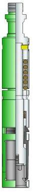
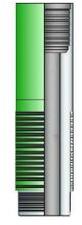
Mill-Out Bottom is used to connect a mill-out extension to a packer.

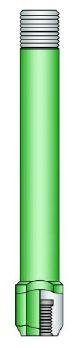
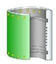
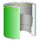
Seal Bore Extension runs below a drillable or retrievable seal bore packers. Seal Bore Extension is run to provide additional sealing bore when a long Seal Bore Assembly is run to accommodate considerable
tubing movement. The Seal Bore Extension has the same ID as the corresponding Packer seal bore it is run with. Thus all seals of a long Seal Assembly seat off in the Seal Bore Extension. If the top set of seal
normally sealing in the Packer bore should get damaged, the Seal Bore Extension still provide a sealing surface for the lower seat.

Guides are threaded bottom subs for Seal Bore Packers, and can be ordered separately or as an integral part of the Packer. They are available as box thread down to accommodate Mill out Extensions or
Seal Bore Extensions or pin thread down to make up with tail-pipe or other accessories down the line. Mill out Extensions are furnished with the standard API tapered thread connections. Other threads are
available on request.
For Packers that will eventually be milled out using the Packer Milling Tool, the Mill out Extension is used to provide the length and inside diameter necessary to accommodate the Mandrel and Catch sleeve of a
standard Milling Tool.

Snap Latch Seal Assembly latches into the packer upon set down (like our Anchor Latch Seal Assembly). It can be removed with straight pull of 10, 000 to 12, 000 lbs. above tubing weight. The Snap Latch Seal Assembly is used where a mechanical indication is required to verify the seal assembly is properly positioned in the packer bore.

Anchor Seal Nipple is an anchoring and sealing device that connects the retrievable tubing string to the upper bore of the Retainer Production Packers. The latch component of the seal nipple provides positive
engagement with the packer. The seal unit maintains the pressure integrity of the connection. The additional no go shoulder is designed to provide a positive set down shoulder at the top of the packer and secondly to prevent excessive intrusion of debris into the latch to packer body inter-face.
Features / Benefits:
NOTE: Feasible distinct sizes of all above accessories could be provided with specific grades of material and end connections; standard or premium thread, as per the customer's requirement.

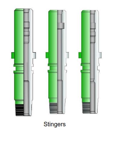
The On/Off Overshot designed to disconnect and connect the tubing string form a production packer that does not require tension or compression to maintain a pack-off. The profile stingers run with the overshot are available in all variety of profiles types and sizes with different end connections and materials as per customers requirement.
Features/Benefits:
Applications: