Our Product / Services
Leading Manufacturer, Supplier & Retailer of PWL Wastewater Treatment Plant and PWF Wastewater Treatment Plant.
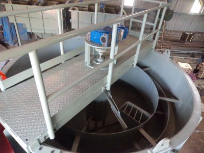
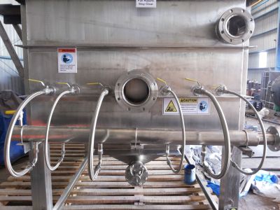
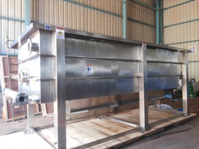
This PWL Wastewater Treatment Plant is widely used in industries such as food, textile, paper, mining and petro-chemical to name a few. It ensures minimum pollution, is extremely user friendly and safe and also requires low maintenance costs. This plant is highly compact and is designed for high capacities. It uses various principles to operate and the manufacturing product employs our state of the art machinery and advanced technical solutions.
Details :
PWL : To ensure high dry solid contents of the skimming, the solid loading (kg solids/m2 free unit surface) is an important design factor. For wastewater containing high solid contents, it is necessary to create sufficient retention time for predewatering of the skimmings. The PWL flotation systems have been designed for the nominal capacities with the solid contents up to 10.00 mg/l
Application :
Features
GA Drawing
Additional Information:
Payment Terms : L/C,
Packaging Details : Sea worthy packing or polythene wrapping
GA Drawing
Standard Units
| Type PWL | 5 | 10 | 15 | 20 | 25 | 30 | 40 | 50 | 60 | 70 | 80 | 90 | 100 | 120 | 140 | 160 | 180 |
|---|---|---|---|---|---|---|---|---|---|---|---|---|---|---|---|---|---|
| Capacity M3/hr | 5 | 10 | 15 | 20 | 25 | 30 | 40 | 50 | 6 | 70 | 80 | 90 | 100 | 120 | 140 | 160 | 45 |
| Free surface M2 | 1.25 | 2.5 | 3.75 | 5 | 6.25 | 7.5 | 10 | 12.5 | 15 | 17.5 | 20 | 22.5 | 25 | 30 | 35 | 40 | 180 |
| Dimensions PWL | 5 | 10 | 15 | 20 | 25 | 30 | 40 | 50 | 60 | 70 | 80 | 90 | 100 | 120 | 140 | 160 | 16000 |
| A-Length mm | 2100 | 2700 | 3200 | 3200 | 3600 | 4300 | 5500 | 6600 | 7800 | 8900 | 10100 | 11300 | 9300 | 11000 | 12800 | 14300 | 3200 |
| B-Width mm | 1200 | 1700 | 1700 | 2400 | 2400 | 2400 | 2400 | 2400 | 2400 | 2400 | 2400 | 2400 | 3200 | 3200 | 3200 | 3200 | 2400 |
| C-Height mm | 1400 | 1500 | 1800 | 2400 | 2400 | 2400 | 2400 | 2400 | 2400 | 2400 | 2400 | 2400 | 2400 | 2400 | 2400 | 2400 | 300 |
| D-Inlet DN/NW | 50 | 65 | 80 | 80 | 100 | 100 | 100 | 150 | 150 | 150 | 150 | 150 | 200 | 200 | 200 | 250 | 200 |
| E-Skimmings DN/NW | 65 | 80 | 100 | 100 | 100 | 150 | 150 | 150 | 150 | 15 | 150 | 150 | 150 | 200 | 200 | 200 | 300 |
| F-Effluent>DN/NW | 65 | 80< | 100 | 100 | 100 | 150 | 150 | 150 | 200 | 200 | 200 | 200 | 250 | 250 | 250 | 300 | 200 |
| G-sediment DN/NW | 65 | 80 | 80 | 80 | 100 | 100 | 100 | 125 | 125 | 125 | 125 | 150 | 150 | 150 | 150 | 150 | 150 |
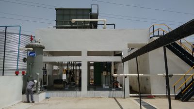
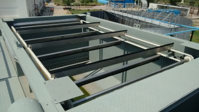
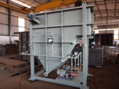
PWF Wastewater Treatment Plant that we supply and manufacture is compact and ensures high levels of user safety as well. The sludge collection compartment can be replaced by a spiral conveyer discharge in case of heavy sludge or a discharge chute otherwise. The aeration systems on the other hand can be executed with air saturation vessel or a multistage pump. This plant promises high efficiency and a long working life without much maintenance.
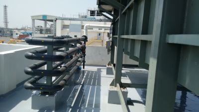
The Aeration systems can be either executed with
The Sludge Collection compartment is optional and can be replaced by
Application
Features
Additional Information:
Payment Terms : L/C,
Graphical Image
GA Drawings For PWF
Process & Instrumentation Diagram
GA For PWF In Steel
GA For Saturation Vessel
GA Detail
| Nozzle |
Qtn. |
Description |
|---|---|---|
|
A |
1 |
Air Inlet |
|
B |
1 |
Bottom Outlet |
|
D |
1 |
Drain |
|
F |
1 |
Feed |
|
H |
1 |
Hand Hole |
|
I |
1 |
Inspection Hole |
|
V |
1 |
Vent |
|
PRV |
1 |
Pressure Relief Valve |
|
PG |
1 |
Pressure Gauge |
|
PT |
1 |
Pressure Transmitter |
|
LC1 & 2 |
2 |
Level Controller |
Standard Units
| Type | PWF | 5 | 10 | 20 | 35 | 50 | 75 | 100 | 150 | 200 |
|---|---|---|---|---|---|---|---|---|---|---|
| Capacity | m3 | 5 | 10 | 20 | 35 | 50 | 75 | 100 | 150 | 200 |
| Effective Plate surface | m2 | 3.5 | 7 | 14 | 25 | 34 | 50 | 70 | 100 | 133 |
| Flow Rate | m/hr | 1.5 | 1.5 | 1.5 | 1.5 | 1.5 | 1.5 | 1.5 | 1.5 | 1.5 |
| Free Surface | m2 | 0.8 | 1.0 | 1.2 | 2.2 | 3 | 4 | 5.3 | 8 | 10.5 |
| Dimensions * | PWF | 5 | 10 | 20 | 35 | 50 | 75 | 100 | 150 | 200 |
| A-Length | mm | 1800 | 2000 | 2700 | 2700 | 4600 | 4600 | 4600 | 4600 | 4600 |
| B-Width | mm | 900 | 1300 | 1300 | 1900 | 2400 | 1600 | 2200 | 2600 | 3000 |
| C-Height | mm | 1970 | 2050 | 2800 | 2800 | 2800 | 3970 | 3970 | 3970 | 4500 |
| D-Inlet | NB | 50 | 65 | 80 | 100 | 150 | 150 | 200 | 200 | 200 |
| E-Skimmings | NB | 80 | 80 | 100 | 100 | 150 | 150 | 150 | 150 | 150 |
| F-Effluent | NB | 80 | 80 | 100 | 150 | 150 | 200 | 200 | 250 | 250 |
| G-Drain | NB | 50 | 80 | 80 | 80 | 80 | 100 | 100 | 100 | 100 |
| H-Bottom Sludge | NB | 80 | 80 | 100 | 100 | 100 | 100 | 150 | 150 | 150 |
| Weight* | PWF | 5 | 10 | 20 | 35 | 50 | 75 | 100 | 150 | 200 |
| Empty weight | kg | 1200 | 1500 | 2200 | 2500 | 3000 | 3500 | 4000 | 5000 | 8000 |
| Full Weight | kg | 2200 | 3500 | 6500 | 8000 | 10000 | 13000 | 16000 | 20000 | 26000 |
Process & Instrumentation 01
| -1 | -3 | -5 | -6 | -8 | -12 |
| PFL 10 Pipe Flocculator 25 m3/hr |
Pressure Pipe DIA.-200 L= 1 m. CYLINDRICAL 6_8 BAR |
DAF-Unit 2.7X 1.9 X 2.8 M (LxWxH) RECTANGULAR MSEP. |
Scraper Thickener K-PACK 1.0 HO |
Recirculation Pump MULTISTAGE 5 m3/hr 6 BAR |
Sludge Pump Excentric Screw Auger |
Process & Instrumentation 02
| Description | Qty. | Function |
|---|---|---|
| Flocculator PVC | 1 | Flocculation |
| 1/2" Ball Valve SS 304 | 6 | Aeration |
| Pressure Pipe | 1 | Pressurisation |
| 1/2" Ball Valve SS 304 | 1 | De-aeration |
| Daf Unit | 1 | ------- |
| Skimmer Drive | 1 | Skimming |
| 1" Ball Valve | 4 | Recirculation |
| Recirculation Pump | 2 | ----DO---- |
| Gauge Valve-1" | 2 | ----DO---- |
| Pressure Indicator | 2 | ----DO---- |
| Check Valve | 1 | Aeration |
| Auger Drive | 1 | Bottom Sludge |
| Flocculant Dosing | 1 | Dosing |
| Alum Dosing | 1 | Dosing |