Products / Services
  • Products / Services
  • Companies
  • Buy Leads
Post Buy Requirement

Level Transmitters

Listing ID #258036

  • Supply Type Manufacturer, Exporter, Supplier
Preferred Buyer From : All over the world

We present highly reliable Level Transmitters to our reputed clients. A study of transmission line theory is required to prove this phenomenon. An equivalent circuit for the coated section is shown....
View More Details
Send Enquiry

Company Information

  • Member Since 14 Years
  • Nature of Business Retailer
  • Year of Establishment 1998

Ask for more detail from the seller

Contact Supplier

Product Details no_img_icon

We present highly reliable Level Transmitters to our reputed clients. A study of transmission line theory is required to prove this phenomenon. An equivalent circuit for the coated section is shown as a ladder network producing the phase shifted error signal. One way to cancel the error signal is to measure the conductive component (c) shown in Figure 3 Method A. Since the 45o relationship exists, the capacitive error component (e) is the same magnitude and can be subtracted from the total output signal, thus effectively canceling the error signal. Another cancellation method use is to introduce a 45º phase shift to the entire measurement as shown in Figure 3, Method B. This automatically cancels the coating error portion because the conductance component (c) still has the same magnitude as the error component (e), resulting in the appropriate level signal. For Continues Level & Volume Measurement Of All Liquids, Slurries & Powders :
  • Electronic cancellation of conductive coating on probes
  • Specially designed to use with strong acids & alkalis
  • Fully insulated probe for conductive liquids
  • No maintenance & probe cleaning v250 khz. Operation
  • Factory calibrated transmitter
  • 4 –20 ma , 3wire
  • 10 – 32 v dc power supply
  • Programmable display & control unit with bar graph
  • Up to 4 change over contact output (h, l, hh &ll)
  • Volume, level & percentage display
Suitable For :
  • All acids
  • Alkalis & chemical solvents milk
  • Beverages
  • Powders latex & paints
  • Water, diesel & edible & non edible oils effluents
Basic Measurement Principle : A capacitor is formed when a level-sensing electrode is installed in a vessel. The metal rod of the electrode acts as one plate of the capacitor and the tank wall (or reference electrode in a non-metallic vessel) acts as the other plate. As the level of the material being measured rises, the air or gas normally surrounding the electrode is displaced by the material's different dielectric constant. The value of the capacitor changes because the dielectric between the two plates has changed. RF capacitance instruments detect this change and convert it into a relay actuation or proportional output signal. The following equation illustrates the capacitance relationship: C = 0.225 K (A+D) Where : C = Capacitance in pico farads K = Dielectric Constant of material A = Area of plates in square inches D = Distance between the plates in inches The dielectric constant is a numerical value between 1 and 100 that relates to the ability of the dielectric (material measured between the plates) to store an electrostatic charge. The dielectric constant of a material is determined in an actual test cell. In actual practice, capacitance change is produced in different ways depending on the material being measured and the level electrode being used. However, the basic principle always applies. If a higher dielectric material replaces a lower one, the total capacitance output of the system will increase. If the electrode is made larger (effectively increasing the surface area) the capacitance output increases; if the distance between measuring electrode and reference decreases, then the capacitance output increases. Non-Conductive Materials : The capacitance changes as material comes between the plates of the capacitor. For example, suppose the sensor and the metal walls are measuring the increasing level of a non-conductive material such as oil. Figure 1 depicts a typical system. While the actual capacitive equation is very complex, it can be approximated for the above example as follows :
C = 0.225 (K air x A air) + 0.225 (K material x A material)
Dair Dmaterial
Since the electrode and tank wall are fixed in place, the distance between them will not vary. Similarly, the dielectric of air (1) and the measured material, oil (3.1), also remain constant. Therefore, the capacitance output of the system example can be reduced to this very basic equation: C = (1 x A air) + (3.1 x A material) As this equation demonstrates, the more material in the tank, the higher the capacitance output will be. The capacitance is directly proportional to the level of the measured material. Conductive Materials : The same logic for nonconductive materials applies to conductive materials, except that conductive material acts as the ground plate of the capacitor rather than the tank wall. This changes the distance aspect of the equation, whereby the output would be comparatively higher than for a nonconductive material. However, it still remains fixed; therefore, as level rises on the vertically mounted sensor, the output increases proportionately. A material is considered conductive when it has a conductivity value of greater than 10 micro Siemens /cm. The level-sensing electrode must be insulated. A non insulated sensor is tip sensitive and acts like a conductive switch. Material Buildup : The most devastating effect on the accuracy of RF capacitive measurements is caused by the buildup of conductive material on the electrode surface. Non-conductive buildup is not as serious since it only represents a small part of the total capacitance. The Level Probe : The probe used in this device is a stainless steel rod, fully insulated with HDPE/PTFE which does not make any direct contact with the medium. The capacitance formed by the probe rod and the conductive material is proportional to the level of material in the tank (ie), as the level increases the capacitance also increases. The Transmitter : A crystal controlled radio frequency sine wave of fixed peak voltage is passed through the capacitance formed by the tank body and the probe in series with a known capacitance. The voltage drop across the fixed capacitor will be 90º out of phase with the applied wave form and is proportional to the tank capacitance. Compensating For Conductive Material Buildup : Coating error is illustrated by the diagram shown in Figure 2. The submerged portion of the electrode generates nearly a pure capacitive susceptance. Since the electrode is insulated, a conductive component is virtually non-existent. However, the upper section of the electrode, coated with conductive material, generates an error signal consisting of a capacitive susceptance and a conductive component. The result is an admittance component that is 45º out of phase with the main level signal.

Specifications

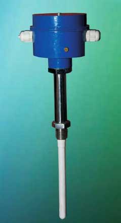
Transmitter & Probe Principle of OperationRF Capacitance/Admittance
Probe Fully Insulated (HDPE/PTFE)SS rod/Coaxial Probe
Probe LengthAs per the tank height
Enclosure Nylon
Compensation for moistureProvided
Enclosure ProtectionWeather proof- IP65
Wetted PartsSS 316/ HDPE/PTFE
Process ConnectionFlanged /screwed
Flange StandardANSI
Flange Size & Rating1 ½" 150 lb.
Mounting Silo Top
Electrical Connection¾" E.T
Power Supply 10 to32 V,DC(or from display unit)
Cable Type & Size3core x 0.75 sq.mm screened PVC cable
Output 4 - 20 mA
Dimensions 65 mm () x 100mm (H)

Control & Display Unit (Micro Controller Based)

Power Supply220V, AC,50 Hz./ 24V,DC
Power Consumption< 10 Watts.
Sensitivity AdjustmentProvided
Enclosure Weatherproof
Mounting Wall mounted / Panel Mounted
Alarms Upper & Lower limit,230V,5A change over contacts
Display 5 Digit LED Display /4Digit LED +20segment Bargraph
Calibration Field Calibration Facility
Accuracy 0.01% of FS
Resolution 1/65000
Dimensions 92mm x92mm x110mm /48mm x 92mm x110mm


Tell us your Buy Requirement to Get Instant Response
Tell us what you need?

Looking for Level Transmitters?

Quantity
Seller Contact Details
  • Seller Albertel Technologies
  • Address Kanjiramattom, Ernakulam, Kerala
Waiting for permission
To search by voice, go to your browser settings and allow access to microphone

Allow microphone access to search with voice