Our Products
We are leaders in the market for providing best range of DIGIMAG250 Full Bore Electromagnetic Flow Meter, Steam Flow Meter Orifice Flow Meter, Steam Flow Meter, Flow Meter and Ultrasonic Water Meter With Amr System

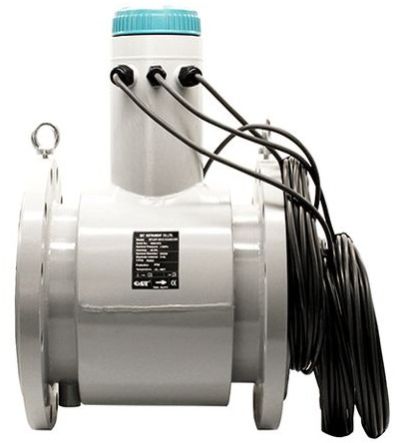
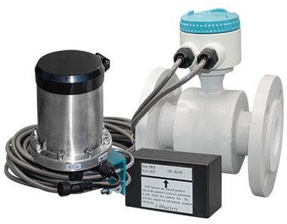
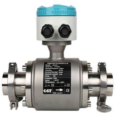
Electromagnetic flow measurement has been in use around the world for 50 years and more, as witnessed by the popularity of these meters that continues unabated in virtually all sectors of industry. Electromagnetic Flowmeters can be used to measure all electrically conductive liquids (> 5 µS/cm) with or without solids, e.g. water, wastewater, sludge, slurries, pastes, acids, alkalis, juices, fruit pulp, etc.
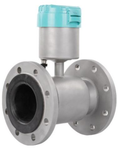
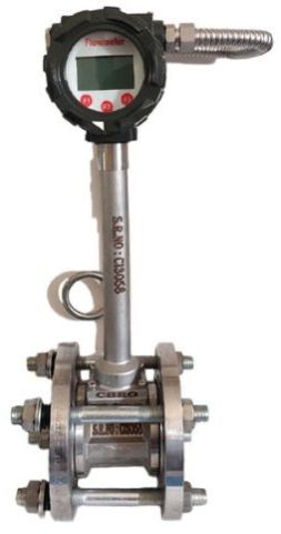
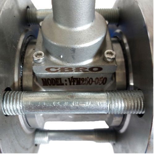
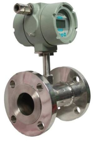
CBRO DIGIMAG250 Full Bore Electromagnetic Flowmeter is suitable for the most demanding applications. It is based on Faraday’s law of Electromagnetic Induction. The meter features flanged construction and is available with choice of liner and electrode material. All meters consist of a sensor and a converter that may be mounted either integral to the sensor or remotely with a field mount kit. CBRO Flowmeters are calibrated at our own Water Flow Calibration Facility. It uses the primary method of measuring the water flow by gravimetric principle. The facility is designed for calibration of flowmeters under controlled and stable flow conditions.
Salient Features:
Applications:
Technical Specifications
| Parameters | Specifications |
|---|---|
| Nominal dia (mm) | 10 to 3000 |
| Working pressure (kg/cm2) | 10, 16, 25, 40 |
| Working temperature | Integral PTFE – 120oC Remote PTFE – 180oC Others – 70oC |
| Electrode material | SS 316L Std.* |
| Sensor lining | Std. Rubber* |
| Display version | Integral/Remote |
| Measuring tube material | SS 304 Std.* |
| Sensor housing material | Std. CS* |
| End connection | Flange/Wafer/Tri-clamp/SMS |
| Flange standard | ANSI 150* |
| Measuring range | 0.2 to 12 m/sec. Bidirectional |
| Accuracy % of measured value | ±O.5% (±O.2% consult factory) |
| Repeatability | ±0.2% of Span |
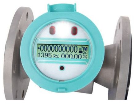
| Display | 2 line LCD |
| Display units | All standard engineering units in m3, litre, gallon, ft3, imperial gallon |
| Output | Std. 4 – 20 mA* |
| Power supply | 12 – 60 V DC or 80 – 300 V AC/DC Solar powered |
| Protection class for sensor | Std. IP 65 Option IP 67/IP 68 for flow tube in remote type |
| Protection class for transmitter | IP 67 |
| Cable length for remote | Std. 10 m* |
| Installation | Inline flanged type |

| Make | CBRO |
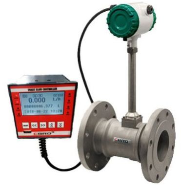
| Model Name/Number | SFM250 |
| Service | Saturated and superheated steam, hot water, thermic fluids in closed pipes |
| MOC of flanges | MS |
| Orifice flange assembly | WNRF class 300 |
| DPT | With display |
| Data logging | 3450 readings or 6900 readings (Optional) |
| Output | 4-20mA |
| Comm Protocol | RS232/485 Modbus Protocol |
| Typical turndown | 103 (Std) |
| Density compensation | Online monitoring and compensation of density |
| Pressure | 22 kg/cm2 Max |
| Size | Max 10 inch |
| Type of flow element | Orifice type |
| MOC of flow element | SS 316 |
| End connection | Sorf flange |
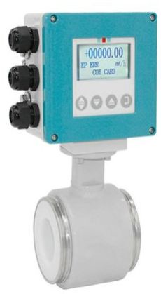
The SFM50 flow meter is applicable for measuring flow rates of saturated and superheated steam, mass flow rates of Boiler feed Water in closed conduits. It is best suited for applications where affordability, reliability and ruggedness are of prime concerns. It can be used as heat energy transfer meter to measure thermal energy using various fluids which are being used as the heat transfer medium. In the conventional system of measurement, the differential pressure generated by orifice plate is measured by DP transmitter. The output from DP transmitter after square rooting is accepted as proportional to flow rate. This assumption is true only when the density is constant. Unfortunately, the density of the compressible fluid is never constant. The density of compressible fluid changes with line pressure and line temperature. Thus, introducing errors in flow rate measurement. Features of Steam Flow Meter
Easy user-friendly programming
Password protected for all modes except display mode
Computer/Printer Interfacing with RS 232/RS 485 port with MODBUS RTU
Fault indication indicated by different error codes
Overflow indicated by blinking display up to 3000 readings (for more readings consult factory)
Data logging facility with 3450/ 6900 number of reading is available
Linear or square root operation
Universal power supply
Suitable for Saturated &/or Superheated Steam
Two-alarm setting configured on pressure input
Steam status indication (Saturated/ Superheated)
Pressure and temperature offsets generated by site condition can be compensated
Mass flow calculation as per ASME algorithm
Additional Information:
Payment Terms : T/T
Delivery Time : 3-4 Weeks or Earlier

The SFMc-150 flow meter is applicable for measuring flow rates of saturated and superheated steam, mass flow rates of Boiler feed Water in closed conduits. It is best suited for applications where affordability, reliability and ruggedness are of prime concerns.
It can be used as heat energy transfer meter to measure thermal energy using various fluids which are being used as the heat transfer medium.
In the conventional system of measurement, the differential pressure generated by orifice plate is measured by DP transmitter. The output from DP transmitter after square rooting is accepted as proportional to flow rate. This assumption is true only when the density is constant. Unfortunately, the density of the compressible fluid is never constant. The density of compressible fluid changes with line pressure and line temperature. Thus, introducing errors in flow rate measurement.
Features of Steam Flow Meter:
Technical Specifications
| Parameter | Orifice | Vortex |
|---|---|---|
| Well established standards | Available | Not Available |
| Suitability for high pressure & temperature application. | Most suitable | Seal fails in the majority of cases after the certain duration |
| Installation | Easy to install | Critical & expensive because of Requirement of specially machined pipe lengths. |
| Existing pipeline modifications for installation | No modifications required. | The design is based on velocity & not on line size. As a result, customer line size & selected flow meter size may differ. |
| Recalibration of transmitter | Easy & can be done in-house | Has to be done on a flow-rig and hence is expensiv |

The SFMc-150 flow meter is applicable for measuring flow rates of saturated and superheated steam, mass flow rates of Boiler feed Water in closed conduits. It is best suited for applications where affordability, reliability and ruggedness are of prime concerns.
It can be used as heat energy transfer meter to measure thermal energy using various fluids which are being used as the heat transfer medium.
In the conventional system of measurement, the differential pressure generated by orifice plate is measured by DP transmitter. The output from DP transmitter after square rooting is accepted as proportional to flow rate. This assumption is true only when the density is constant. Unfortunately, the density of the compressible fluid is never constant. The density of compressible fluid changes with line pressure and line temperature. Thus, introducing errors in flow rate measurement.
Features of Steam Flow Meter:

Accumax offers smart flow meter devices, which provide accurate, cost effective and contemporary flow measurement for household and industries application. It is an advanced and highly accurate ultrasonic water meter with AMR (Automatic meter reading) technology. It can be used for industrial application as well as for residentials application. The ultrasonic AMR water flow meter measurement is based on the transit time method also It has full information LCD display, which is easy to read the data and see the alarms. Ultrasonic AMR meter has wide applications as it’s based on LORA technology and automatic reading meter (AMR)
Features:
Application:-

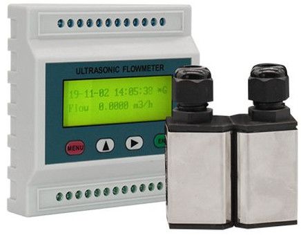
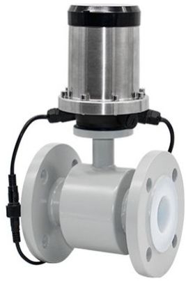
CBRO UFM250I inline type Flanged Battery Operated Ultrasonic Flowmeter provides abundant capabilities for accurate liquid flow measurement. It is widely used in remote location applications where Field Electric supply is not available.
Salient Features:
Applications:
Technical Specifications
| Parameters | Specifications |
|---|---|
| Make | CBRO |
| Model | UFM250! |
| Technical characteristics | Low power consumption, digital process technology with stable piezoelectric sensor |
| Accuracy | ±1% of reading (Optional ±0.5%) |
| Repeatability | 0.2% of Span |
| Display | Total flow, flow rate, velocity, working time & date, signal intensity, quality & battery status |
| Output | RS 485, 4 – 20 mA, Pulse for total flow (All outputs need external power supply 24 V DC) |
| Communication interface | GSM, RS 485 (Modbus RTU), UART |
| Operation | Inside keypad available |
| Sampling period | 0.5 sec |
| Environment temp. | Up to 65oC |
| Water temp. | 5 to 70oC |
| Power supply | Li-ion battery, solar powered |
| Enclosure class | IP 68 |
| Pipe size | DN 40 – 600 |
| Flange standard | ANSI, IS, DIN PN, BS |
| Pressure transmitter | Range 0-16 kg/cm2, IP 68, 1/2″ male threaded, accuracy 0.25% |

Salient Features:
Applications:
Technical Specifications
| Parameters | Single Path | Two Path | Four Path |
|---|---|---|---|
| General | |||
| Make | CBRO | ||
| Model | UFC250I | ||
| No. of Sensors | 2 | 4 | 8 |
| Operating principle | Transit time technology | Transit time technology | Transit time technology |
| Operating pressure | 20 kg/cm2 max | 20 kg/cm2 max | 20 kg/cm2 max |
| Application | Raw, clear, sewage water & homogeneous liquids | Raw, clear, sewage water & homogeneous liquids | Raw, clear, sewage water & homogeneous liquids |
| Transmitter | |||
| Power supply | 24 V DC ± 20% 110 V AC ± 15% 240 V AC ± 15% Solar powered | 24 V DC ± 20% 110 V AC ± 15% 240 V AC ± 15% Solar powered | 24 V DC ± 20% 110 V AC ± 15% 240 V AC ± 15% Solar powered |
| Velocity | ±12 m/sec. Bidirectional | ±12 m/sec. Bidirectional | ±12 m/sec. Bidirectional |
| Display | 2 lines, 16 characters LCD with backlight flow rate, velocity, totaliser | 2 lines, 16 characters LCD with backlight flow rate, velocity, totaliser | 2 lines, 16 characters LCD with backlight flow rate, velocity, totaliser |
| Units | User configurable English/Metric | User configurable English/Metric | User configurable English/Metric |
| Totaliser | FWD, NET, REV | FWD, NET, REV | FWD, NET, REV |
| Output – Analog | 4 – 20 mA Std.* | 4 – 20 mA Std.* | 4 – 20 mA Std.* |
| Accuracy | ±1% of reading @ rate >0.5 m/sec. | ±0.5% of reading @ rate >0.5 m/sec. | ±0.5% of reading @ rate >0.5 m/sec. |
| Repeatability | 0.2% of Span | 0.2% of Span | 0.2% of Span |
| Protection class | IP 65 | IP 65 | IP 65 |
| Dimensions | 251X190X96 mm | 500x400x300 mm | 500x400x300 mm |
| Weight | < 2.5 kg | < 4.5 kg | < 6.5 kg |
| Security | Keypad lockout, access code enabled | Keypad lockout, access code enabled | Keypad lockout, access code enabled |
| Self diagnostic feature | Available | Available | Available |
| Facility to measure and display each path velocity | NA | Available | Available |
| Ability to work even though one or more path does not work | NA | Available | Available |
| Flow and totaliser unit programmability | Available | Available | Provided |
| Password protection for configuration data | Available | Available | Available |
| Totaliser value retention in the event of power fail condition | Available | Available | Available |
| RS 485 Modbus RTU Protocol | Available | Available | Available |
| Lightening protection units | Available | Available | Available |
| Sensor | |||
| Suited temp. – Std. | -40oC to 1200C | -40oC to 1200C | -40oC to 1200C |
| Pipe size | 50 – 6000 mm dia | 350 – 6000 mm dia | 1000 – 6000 mm dia |
| Protection class | IP 65, IP 67, IP 68 | IP 65, IP 67, IP 68 | IP 65, IP 67, IP 68 |
| Sensor dimensions | 186 mm with 20 mm bore size | 186 mm with 20 mm bore size | 186 mm with 20 mm bore size |
| Weight | < 1.5 kg | < 1.5 kg | < 1.5 kg |
| Cable length | 6 m std. can be extended up to 300 m | 6 m std. can be extended up to 300 m | 6 m std. can be extended up to 300 m |

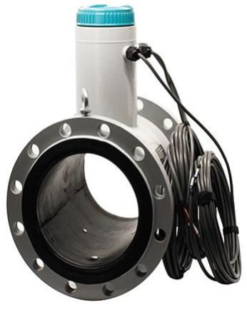
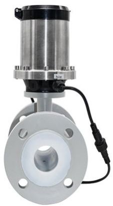
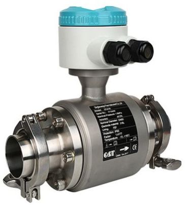
Electromagnetic Flow measurement has been in use around the world for 50 years and more, as witnessed by the popularity of these meters that continues unabated in virtually all sectors of industry. Electromagnetic Flowmeters can be used to measure all electrically conductive liquids (> 5 µS/cm) with or without solids, e.g. water, wastewater, sludge, slurries, pastes, acids, alkalis, juices, fruit pulp, etc.
Insertion Type Electromagnetic Flowmeter is suitable for the most demanding applications. They are based on Faraday’s law of Electromagnetic Induction. The meter features sensor tube and ball valve assembly.
Salient Features:
Applications:
Technical Specifications
| Parameters | Specifications |
|---|---|
| Nominal dia (mm) | > 100 |
| Working pressure (kg/cm2) | 20 |
| Working temperature | Up to 120oC |
| Electrode material | SS 316L Std.* |
| Sensor lining | NA |
| Display version | Integral/Remote |
| Measuring tube material | SS 316 Std.* |
| Sensor housing material | NA |
| End connection | NA |
| Flange standard | NA |
| Measuring range | 0.2 to 12 m/sec. Bidirectional |
| Accuracy % of measured value | ±2% |
| Repeatability | ±0.2% of Span |
| Display | 2 line LCD |
| Display units | All standard engineering units in m3, litre, gallon, ft3, imperial gallon |
| Output | Std. 4 – 20 mA* |
| Power supply | 12 – 60 V DC or 80 – 300 V AC/DC Solar powered |
| Protection class for sensor | Std. IP 68 |
| Protection class for transmitter | IP 67 |
| Cable length for remote | Std. 10 m* |
| Installation | Insertion type with use of isolating ball valve assembly on pipeline |

Benefits:
Applications:
This series of flow meters from CBRO is a high-resolution answer to your metering needs. Made of stainless steel, the meters in the HTFM series offer wide measuring ranges and low pressure loss. A helical-gear design gives these meters lower pressure drop compared to other meters and ideal for metering high viscosity polyurethanes, polymers, glues, sealants, and heavy fuel oils.
CBRO offers these specialized helical gear flow meters suitable for a variety of industrial application,
including:
CBRO Liquid Turbine Flow Meter is internally developed and perfected by CBRO Instrument. Over the years, CBRO Liquid Turbine Flow Meter has been commissioned in many parts of the world, received praise from end-users and industrial leaders. CBRO Instrument Turbine Flow Meter offers two accuracy classes, 0.5%R and 0.2%R. Its simple structure allows a small pressure loss and virtually no maintenance requirements. The Thread Connection Turbine Flow Meter offers two types of converter options, Compact Type and Remote Type. Our users can select the preferred converter type depending on the commissioning environment.
Advantages:-
Thread Turbine Flow Meter Advantages
CBRO strives to provide high-quality products with economical cost.
CBRO Instrument Liquid Turbine Meter provides high accuracy of 0.2% R and a wide range of applications to non-conductive liquids, such as fuel oil, ultrapure water and gasoline. These make the turbine meter more popular compare to Electromagnetic Flow Meter in the oil industry, purifying process and distilleries. The CBRO Instrument meter also has an amazingly wide turndown ratio of 20:1, combined operate reliably in both high and low flow rates and produce excellent repeatability as low as 0.05%.
The Thread connection Turbine Flow Meter is known for its application to smaller pipe sizes. limited installation space, Thread connection Turbine Flow Meter is always preferred over Flanged connection and Tri-Clamp connection Turbine Meters.
Application:-
Thread Turbine Flow Meter Applications
CBRO Instrument Liquid Turbine Meters offers both standard SS304 body and SS316 body. Because of its wide working temperature and pressure range, it is capable of measuring various mediums and commissioning into extreme working conditions.
CBRO Instrument Liquid Turbine Meters are popular in the Oil & Gas industry, Chemical industry, and Water industry. The Thread connection version is designed exclusively for smaller size pipes. Our standard size range for Thread Connection Turbine meter is from DN4DN100.
Due to its high accuracy and fast response time, CBRO Instrument Liquid Turbine is often integrated into the Industrial Internet of Things, together with valves and pumps to achieve smart process control, for example, solvents batching, blending, storage and off-loading systems. Kindly contact our sales engineers if there are questions related to integrating CBRO Liquid Turbine Meters into your existing plant IOT.
Installation :-
Tri-Clamp Turbine Flow Meter Installation and Maintenance
Before the installation, it is crucial to communicate with our sales engineers regarding the working conditions and medium the meter designs to measure.
The installation of the Q&T Tri-Clamp Liquid Turbine Meter involves minimal effort. Comes with the product, users will receive a pair of clamps. During installation, the users will not need additional tools for Tri-Clamp type Turbine Flow Meter.
The user needs to keep in mind these three factors while carrying out the installation.
1. There should be at least ten pipe diameter lengths of straight pipe upstream of the Turbine Meter and five pipe diameter length of straight pipe length downstream of the Turbine Meter, with the same nominal diameter size.
2. Valves and Throttling devices needed to install downstream of the flow meter.
3. The arrow indicated on the meter body is the same as the actual flow.
If there are specific questions regarding the installation of the Q&T Instrument Turbine Meter, kindly contact our sales engineers for assistance.

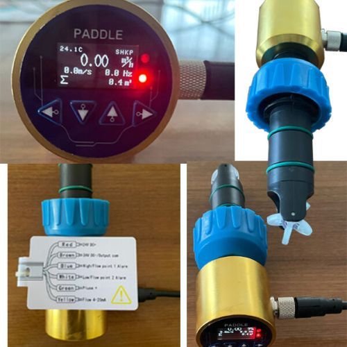
Paddle Wheel Flow Meter, which is easy to operate and gives accurate and reliable measuring of flow. The flow and the revolutions of the paddle wheel are proportional to each other. Thus, by spinning the paddle wheel with the force from the flowing fluid, it becomes possible to measure the rate of this flow from the number of revolutions. A paddle wheel flow meter is used for volumetric total flow and/or flow rate measurement since it has a relatively simple working principle. When fluid flows through the turbine meter, it impinges upon turbine blades that are free to rotate about an axis along the center line of the turbine housing. The angular (rotational) velocity of the turbine rotor is directly proportional to the fluid velocity flowing through the turbine.
Features:-
Application
Various Modes :-

CBRO Make Digital Flow Meter with Telemetry System as per the latest Central Groundwater Authority(CGWA) Guidelines. Also, this Digital Flow Meter with a Telemetry system is easy to install and user-friendly. It provides an IoT platform for water meters which is suitable for data acquisition from any remote location. Also, its Cloud platform having Real-Time Dashboard that allows viewing all analytical parameters as per CGWA guidelines.
Alerts or Notifications during parameter exceedance will be received through Email and SMS.
Features:
Two variants are available:
Applications:

Adept POWERMAG2500 Full Bore Electromagnetic Flowmeter is a battery Powered Electromagnetic Flowmeter. It is mostly used in the applications where Electric Supply is not available and accurate Flow measurement is essential. The battery powers the Flowmeter for minimum 5 years. AMR Facility like GSM or GPRS is available in the Model. We offer Water Flow Meters with high accuracy rate. Suitable for all types of conductive fluids and water and waste water applications. Measure the rate of flow of slurries or conducting liquids flowing in closed pipes.
Salient Features:
Applications:

\n
Salient Features:
\n\n
Applications:
\nTechnical Specifications
| Parameters | Specifications |
|---|---|
| Transmitter | |
| Make | CBRO |
| Model | UFC250W |
| Power supply | 24 V DC ± 20% 110 V AC ± 15% 240 V AC ± 15% Solar powered |
| Velocity | ±12 m/sec. Bidirectional |
| Display | 2 lines, 16 characters, LCD with backlight, flow rate, velocity, totaliser |
| Units | User configurable English/Metric |
| Totaliser | FWD, NET, REV, BATCH (Gallons, ft3, barrels, lbs, m3) |
| Output | 4 – 20 mA DC Std.* |
| Accuracy | ±1% of reading @ rate > 0.5 m/sec. (Optional ±0.5% of reading) |
| Repeatability | 0.2% of Span |
| Protection class | IP 65, IP 67 |
| Dimensions | 251x190x96 mm |
| Weight | < 2.5 kg |
| Security | Keypad lockout, access code enabled |
| Sensor | |
| Suited temp. – Std. | -40oC to 120oC |
| Suited temp. – High | -40oC to 250oC |
| Pipe sizeS Sensor M Sensor L Sensor |
15 – 80 mm 50 – 700 mm 400 – 6000 mm |
| DimensionsS Sensor M Sensor L Sensor |
45x30x30 mm 60x45x45 mm 80x70x55 mm |
| WeightS Sensor M Sensor L Sensor |
< 0.3 kg < 0.5 kg < 1.0 kg |
| Protection class | IP 65, IP 67, IP 68 |
| Cable length | 6 m std. can be extended up to 300 m |
| Flexible belts | SS belt according to pipe size |
| Portable case | NA |

CMF250-20 Series Coriolis mass flow meter is designed according to micro motion and Coriolis principle. It is a leading precision flow and density measurement solution offering .
The Coriolis flow meter worked on the Coriolis effect and was named. Coriolis flow meters are considered to be true mass flow meters because they tend to measure mass flow directly, while other flow meter techniques measure volume flow.
Advantages :-
Coriolis Type Flow Meter Advantages
It has high measurement accuracy, standard accuracy 0.2%; And the measurement is not affected by the physical properties of the medium.
Coriolis type flow meter provide a direct mass flow measurement without the addition of external measurement instruments. While the volumetric flow rate of the fluid will vary with changes in density, the mass flow rate of fluid is independent changes.
Flow meters are operated by flow characteristics such as turbulence and flow distribution. Therefore, upstream and downstream direct pipe operating flow regulation requirements are not required.
Application :-
Petroleum, such as crude oil, coal slurry, lubricant and other fuels.
High viscosity materials, such as asphalt, heavy oil and grease;
Suspended and solid particulate matter materials, such as cement slurry and lime slurry;
Easy-to-solidified materials, such as asphalt
Accurate measurement of medium- and high-pressure gases, such as CNG oil and gas
Micro-flow measurements, such as fine chemical and pharmaceutical industries;
Installation :-
Coriolis Mass Flow Meter Installation
1. Basic Requirements on installation
(1)Flow direction should be in accordance with PHCMF sensor flow arrow.
(2)Properly supporting is required for preventing tubes vibrating.
(3)If a strong pipeline vibration is inevitable, it is recommended to use a flexible tube to isolate the sensor from the pipe.
(4)Flanges should be kept parallel and their center points should be located on the same axis to avoid subsidiary force generation.
(5)Installation vertically, make the flow from the bottom up when measuring, meanwhile, the meter should not be installed on the top to prevent air getting trapped inside the tubes.
2.Installation Direction
In order to ensure the reliability of the measurement, the ways of installation should consider the following factors

CBRO series gas turbine flow meter is a new generation of high-precision and high-reliability gas precision measuring instrument, which is based on the advanced technology of flow meters domestic and abroad. It has excellent low-pressure and high-pressure metering performance, various signal output modes and low sensitivity to fluid disturbance. It is widely used for natural gas, coal-based gas, liquefied gas and other gases application.
Advantages :-
Gas Turbine Flow Meter Advantages and Disadvantages
Gas turbine flow meter is with advanced rectification technology and dust-proof structure. It is with built-in temperature and pressure sensors which can achieve automatically compensation to make sure high accuracy. Gas turbine flow meter provides good solution for custody transfer between parties.
Compared with precession vortex flow meter, gas turbine flow meter is with low pressure loss, low initiating flow and wider measurement range. The display of gas turbine flow meter support to rotate 350°, easy to read data in different directions.
Application Areas:-
Various Modes :-
Features :-
Important Tips :-
Electro-magnetic flow meters suffer from the drawback that the flowing media or liquid must be conductive in nature, whereas such is not the case with Turbine Flow meter, which provides excellent performance even in non-conductive liquids like kerosene, petroleum, vegetable oil etc
Modular type ultrasonic flow meter is one type ultrasonic flow meter with small size and competitive price. It’s working based on transmit-time working theory. One ultrasonic sensor send ultra-sound wave and another one sensor could receive this wave. The transmit time from send to receive have relationship with the velocity of flow speed. Then, converter could calculate the flow speed based the transmit time.
Advantages :-
Modular Type Ultrasonic Flow Meter Advantages and Disadvantages
1. Modular type ultrasonic flow meter is different with other type ultrasonic flow meters. It have much smaller size and could be installed into instrument box easily via DIN rail. It will save installation space.
2. It have multiple functions, such as LCD display, 4-20mA, pulse and RS485 output. No pressure loss, measurement is not affected by temperature and pressure changes. And the accuracy for it could reach ±1%.
3. Reliable empty full tube detection technology, Excellent low flow rate measurement performance, turndown ratio 100:1.
4. As a professional manufacturer, we could produce it with solar panel power system also. It’s very convenient for working site where don’ t have external power supply.
Application :-
Modular type ultrasonic flow meter used in tap water, heating, water conservancy, metallurgy, chemical, machinery, energy and other industries.
It can be used for production inspection, flow verification, temporary inspection, flow inspection, water meter horizontal debugging and energy saving monitoring.
It is a tool and meter for timely detection of flow.
Installation:-
Modular Type Ultrasonic Flow Meter Installation
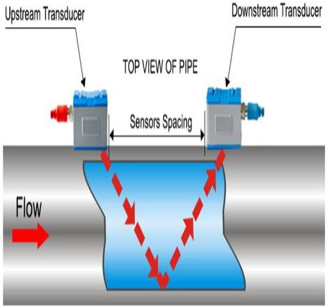
“V” method installation:
The “V” method installation is a relatively standard installation method, which is easy to use and accurate in measurement. When installing the two sensors, the center line of the two sensors can be aligned horizontally with the axis of the pipeline. It’s used on DN15mm and DN400mm.
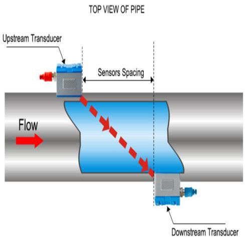
“Z” method installation:
“Z” method of installation is the most commonly used method also. It is characterized by direct transmission of ultrasonic waves in the pipeline, no reflection (called single sound path), low signal attenuation loss. It’s used on DN100mm to DN6000mm.
Modular Type Ultrasonic Flow Meter Maintenance
1. Always observe whether the sensor power cable and transmission cable (or wire) of the instrument are damaged or aging. You need to protect the rubber sheath outside the cable.
2. For the clamp on type transducer ultrasonic flow meter, it is necessary to check whether the transducer is loose or not; whether the adhesive between it and the pipe is normal.
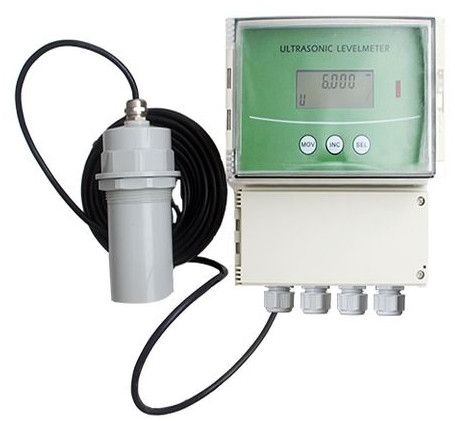
Partially filled pipe electromagnetic flow meter is a kind of volume flow meter. It was specially designed for partially filled pipe. It can measure liquid volume from 10% level of the pipe to 100% level of the pipe. It’s accuracy can reach to 2.5%, very accurate for irrigation and waste water liquid measurement. It use remote LCD display so users can read the flow measurement easily. We also provide solar power supply solution for some remote areas where has no power supply.
Advantages :-
Partially filled pipe electromagnetic flow meter Advantages & Disadvantages
Partially filled pipe electromagnetic flow meter can measure partially filled pipe liquid flow, it is very popular in irrigation.
Its can use solar power supply, this type is very suitable for remote areas where has no industrial power supply.
It adopts safe and durable material, service life is longer than normal products. Normally, it can work at least 5-10 years or longer.
We use an accurate mini ultrasonic level meter for its liquid level measurement then the flow meter will record the liquid use this parameter to measure liquid flow.
Application :-
Partially filled pipe electromagnetic flow meter can measure water, waste water, paper pulp, etc. We use rubber or polyurethane liner on it, so it can measure most of none corrosive liquid. It is mainly used in irrigation, water treatment, etc.
It withstand -20-60 deg C media temperature, and it was very durable and safe.
Installation :-
Partially Filled Pipe Electromagnetic Flow Meter Installation and Maintainance
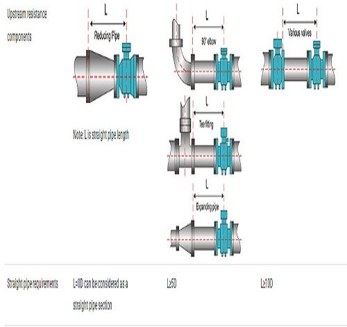
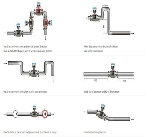
1.Installation Partially filled electromagnetic flow meter should be installed correctly to ensure good measurement. Normally we need leave 10D(10 times of diameter) straight pipe distance before partially filled pipe electromagnetic flow meter and 5D behind partially filled pipe electromagnetic flow meter. And try to avoid elbow/valve/pump or other device which will influent the flow speed. If the distance is not enough, then please install flow meter according to follow picture.
2.Maintenance Routine maintenance: only need to make periodic visual inspections of the instrument, check the environment around the instrument, remove dust and dirt, ensure that no water and other substances enter, check whether the wiring is in good condition, and check whether there are newly installed strong electromagnetic field equipment or newly installed wires near the instrument Cross-instrument. If the measuring medium easily contaminates the electrode or deposits in the measuring tube wall, it should be cleaned and cleaned regularly. 3.Fault finding: if the meter is found to work abnormally after the flow meter has been put into operation or normal operation for a period of time, the external conditions of the flow meter should be checked first, such as whether the power supply is good, whether the pipeline is leaking or in a state of partial pipe, whether there is any in the pipeline Whether air bubbles, signal cables are damaged, and whether the output signal of the converter (that is, the input circuit of the subsequent instrument) is open. Remember to dismantle and repair the flow meter blindly. 4.Sensor inspection 5.Converter check

Flange thermal gas mass flow meter is one of kind mass flow meter which Is popular in industrial applications is the way they are designed and built. The feature is no moving parts, nearly unobstructed straight through flow path, require no temperature or pressure corrections and retain accuracy over a wide range of flow rates. Straight pipe runs can be reduced by using dual-plate flow conditioning elements and installation is very simple with minimal pipe intrusions. Flange thermal gas mass flow meter size from DN10DN2000mm
Advantages :-
Flange thermal gas mass flow meter advantanges :
(1)Wide range ratio 1000:1;
(2)Large diameter, low flow rate, negligible pressure loss;
(3)Direct mass flow measurement without temperature and pressure compensation;
(4)Very sensitive for low flow rate measurement;
(5)Easy to design and select, easy to install and use;
(6)Suitable for all kinds of single or mixed gas flow measurement Could measure gas with flow velocity from 100Nm/s to 0.1Nm/s, which can be used for gas leak detection;
(7) No pressure loss or very small pressure loss.
Application :-
Flange thermal gas mass flow meter application:
Thermal gas air flow meter widely use for Electric power, Petrochemical industry, Glass, Ceramics and Building materials industry, and mainly be used to meausre Dry gas, such as Air, Natural gas, LPG gas, Biogas, ect. But thermal gas mass flow couldn’d be used to measure Vapour, Humidity gas and Ethyne.
Installation :-
nge thermal gas mass flow meter installation:
Observe the recommended inlet and outlet requirements.
Good engineering practice is necessary for the associated pipe work and installation.
Ensure correct alignment and orientation of the sensor.
Take measures to reduce or avoid condensation (e.g. install a condensation trap, thermal insulation, etc.).
The maximum permitted ambient temperatures and the medium temperature range must be observed.
Install the transmitter in a shaded location or use a protective sun shield.
For mechanical reasons, and in order to protect the pipe, it is advisable to support heavy sensors.
No installation in where large vibration exists
No exposure in the environment containing a lot of corrosive gas
No sharing power supply with frequency converter, electric welding machine and other machines which can make power-line interference.
Daily maintenance for flange thermal gas mass flow meter:
In the daily operation of the thermal gas mass flowmeter, check and clean the flowmeter, tighten the loose parts, find and deal with the abnormality of the flowmeter in operation in time, ensure the normal operation of the flowmeter, reduce and delay the wear of components, Extend the service life of the flowmeter. Some flowmeters will become fouling after being used for a period of time, and it must be cleaned by pickling etc. depending on the degree of fouling
Electromagnetic flow meter is one of the most popular flow meters. Flange type electromagnetic flow meter has been used for more than 50 years worldwide. It is widely used for all conductive liquids in every industry, such as water, acid, alkali, milk, slurry etc. Since founded in 2005, CBRO has sold more than 600 thousand electromagnetic flow meters to provide the solutions for clients in different work conditions.
Advantages :-
Electromagnetic Flow Meter Advantages and Disadvantages
The main advantages of using electromagnetic flow meter is that it is with no moving parts, no pressure loss and require very less maintenance.
Flange type magnetic flow meter can be made large size range from DN3-DN3000mm and with bi-directional flow measurement. CBRO mag flow meters are with built-in self-diagnosis function and support data record / bluetooth function and various kinds of output signals. Electromagnetic flow meter will be affected if there’s strong magnetic filed in the surrounding environment.
Application :-
Flange Electromagnetic Flow Meter Installation Requirement
Electromagnetic flow meter is widely used in water treatment, food industry, pharmaceutical, petrochemical, paper mill, chemical monitoring etc.
In the metallurgical industry, it is often used to control the flow of cooling water for continuous steel casting, continuous steel rolling, and steel-making electric furnaces;
In the field of water supply and drainage in public utilities, electromagnetic flow meters are often used for the transfer measurement of finished product water and raw water in water plants;
In the pulp process of the paper industry, electromagnetic flow meters are involved in the measurement of the flow of grinding pulp, water, acid, and alkali;
In the coal industry, measuring coal washing and pipeline hydraulic conveying coal slurry.
For food and beverage industries, it is used for beer and beverage filling measurement.
For chemical and petrochemical industries, it is used to measure corrosive liquids, such as acids and alkalis etc
Installation :-
Flange Electromagnetic Flow Meter Installation Requirement
In order to obtain a stable and accurate flow measurement, it is very important that the flow meter is installed correctly in the pipe system.
Do not install the meter near equipment that produces electrical interference such as electric motors, transformers, variable frequency, power cables etc.
Avoid locations with pipe vibrations for example pumps.
Do not install the meter close to pipeline valves, fittings or impediments which can cause flow disturbances.
Place the meter where there is enough access for installation and maintenance tasks.
Flange ultraosnic flow meter is one kind of economy liquid flow meter which mainly measure various of pure liquid, such as:Clean water, Sea water, Dringking water, River water, Alcohol etc. And it is suitable for continuously measuring flow and heat of clean and uniform liquids without large concentration suspended particles or gases industrial environment.
Advantages :-
Accuracy better than ±1.0% High reliability, high performance, low price
Bi-directional flow measurement No moving parts, no wear, no pressure loss, Maintenance-free Measuring conductivity liquid and Non-conductivity liquid Display instantaneous flow, Total flow, Heat, Positive flow, Negative flow High precision machined pipe sections, the sensor is installed before leaving the factory to ensure high measurement accuracy
Installation :-
Integral Display Flange Ultrasonic Flow Meter Installation Requirement
Generally, the following principles should be followed:
To select a pipe section filled with fluid, such as a vertical part of the pipeline or a horizontal pipe section filled with fluid.
The measuring point should be 10 times the diameter from the upstream and the straight pipe section within 5 times the diameter from the downstream, and the distance from the valve outlet should be as far as possible.
Ensure the temperature at the measuring point is within the working range.
Fully consider the fouling condition of the inner wall of the pipe, and try to select a non-scaling pipe section for measurement. When it cannot be satisfied, fouling should be considered as a lining for better measurement accuracy.
Select pipe sections with uniform and dense pipes that are easy for ultrasonic transmission.
Please refer to the two examples on the right for the selection of measuring points.
Water Temperature And Sound Speed Table
| TEMPERATURE(℃ ) | SOUND SPEED (M/S) | TEMPERATURE(℃) | SOUND SPEED (M/S) |
| 0 | 1403 | 50 | 1541 |
| 5 | 1427 | 55 | 1546.5 |
| 10 | 1447 | 60 | 1552 |
| 15 | 1464 | 65 | 1553.5 |
| 20 | 1481 | 70 | 1555 |
| 25 | 1494 | 75 | 1555 |
| 30 | 1507 | 80 | 1555 |
| 35 | 1516.5 | 85 | 1552.5 |
| 40 | 1526 | 90 | 1550 |
| 45 | 1533.5 | 95 | 1547 |
| 100 | 1543 | ||

Remote Wallmounted Vortex Flow Meter is used in numerous branches of industry to measure the volume flow of liquids, gases and steam. Applications in the chemicals and petrochemicals industries, for example, in power generation and heat-supply systems involve widely differing fluids: saturated steam, superheated steam, compressed air, nitrogen, liquefied gases, flue gases, carbon dioxide, fully demineralized water, solvents, heat-transfer oils, boiler feedwater, condensate, etc.
Advantages :-
Vortex flow meter advantages and disadvantages
Vortex flow meter body is robust and universally applicable for liquids, gases and steam, optimized for steam applications. In gas measurement, vortex flow meter could achieve high accuracy ±0.75%±1.0% of reading ( gas ±1.0%, liquid ±0.75%); which could use in custody transfer , while the metal tube rotameter or orifice plate usually use for process control. With a variety of signals outputs and selection, such as 4-20mA, pulse with HART or pulse with RS485 are selectable.
In the electronic device of measuring flow, vortex flow meter is the only one could resist wide temperature range up to highest temperature 350, digital flow meter highest process temperature.
Application :-
Vortex flow meter applications
Vortex flow meter is professional in measuring non-conductive liquids, gases, saturated and superheated steam, especially for steam measurement trade settlement.
Except work as flow meter, vortex flow meter can also work as heat meter to measure the Gross/net heat of steam and hot water.
Vortex flow meter usually monitor the compressor output and evaluation of Free Air Delivery (FAD)
There has lots of Industrial gases, such as natural gas, nitrogen gas, liquefied gases, flue gases, carbon dioxide etc, all could use vortex flow meter.
In many factories, compressed air monitoring is very important, vortex flow meter also could use for process control.
Besides the different gases measurement, vortex flow meter could also used for light oil or any purified watersuch as thermal oils, Desalinated water, demineralized water, RO water, boiler feed water, condensate water etc.
In the Chemicals and petrochemicals industries, there also has lots of gases or liquid could use vortex flow meter for monitoring.
Installation :-
Vortex Flow Meter Installation Requirements
The installation of vortex flow meter has higher requirements, to guarantee the better accuracy and working properly.
Vortex flow meter installation should keep away from the electric motors, big frequency converter, power cable, transformers, etc.
Do not install in the position where there has bends, valves, fittings, pumps etc, which could cause flow disturbances and influence the measurement.
The front straight pipe line and after straight pipe line should follow below suggestion.

Insertion type thermal gas mass flow meter is one of kind mass flow meter which. Is popular in industrial applications is the way they are designed and built. The feature is no moving parts, nearly unobstructed straight through flow path, require no temperature or pressure corrections and retain accuracy over a wide range of flow rates. Straight pipe runs can be reduced by using dual-plate flow conditioning elements and installation is very simple with minimal pipe intrusions. Insertion type thermal gas mass flow meter size from DN40DN2000mm.
Advantages :-
Insertion type thermal gas mass flow meter advantanges :
(1)Wide range ratio 1000:1;
(2)Large diameter, low flow rate, negligible pressure loss;
(3)Direct mass flow measurement without temperature and pressure compensation;
(4)Very sensitive for low flow rate measurement;
(5)Easy to design and select, easy to install and use;
(6)Suitable for all kinds of single or mixed gas flow measurement Could measure gas with flow velocity from 100Nm/s to 0.1Nm/s, which can be used for gas leak detection;
(7) No pressure loss or very small pressure loss.
Application :-
Insertion type thermal gas mass flow meter application:
Thermal gas air flow meter widely use for Electric power, water treatment, Petrochemical industry, Glass, Ceramics and Building materials industry, and mainly be used to meausre Dry gas, such as Air, Natural gas, LPG gas, Biogas, ect.But thermal gas mass flow couldn’t be used to measure Vapour, Humidity gas and Ethyne.
Installation :-
Insertion type thermal gas mass flow meter installation:
Regardless of whether the flowmeter is installed vertically or horizontally, keep the flowmeter in a horizontal state.
In situations where accidental gas stop or accidental gas stop will inevitably cause major irreversible losses, bypass must be installed.
There should be at least a 10D straight pipe section in the front of the flowmeter and a 5D (D is the pipe diameter) straight pipe section at the rear.
If the instrument is installed outdoors, a sunshade should be added to avoid the sun and rain.
Make sure that there is no strong magnetic field, strong electric field and strong mechanical vibration near the flowmeter.
The static grounding of the flowmeter should be reliable, but it cannot be shared with strong current grounding.
The surrounding environment should confirm that there is no corrosive effect on aluminum alloy.
Ensure that the gas flow direction is consistent with the arrow direction on the flowmeter.
Welding operations are prohibited in an explosive environment.
Insertion type thermal gas mass flow meter maintenance:
In the daily operation of the thermal gas mass flowmeter, check and clean the flowmeter, tighten the loose parts, find and deal with the abnormality of the flowmeter in operation in time, ensure the normal operation of the flowmeter, reduce and delay the wear of components, Extend the service life of the flowmeter. Some flowmeters will become fouling after being used for a period of time, and it must be cleaned by pickling etc. depending on the degree of fouling
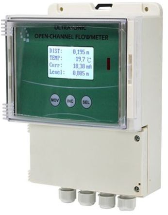
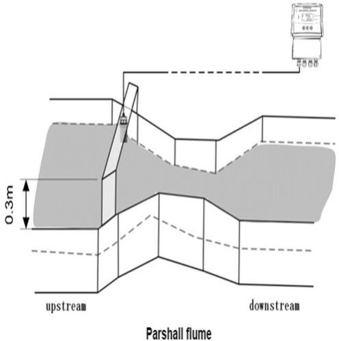
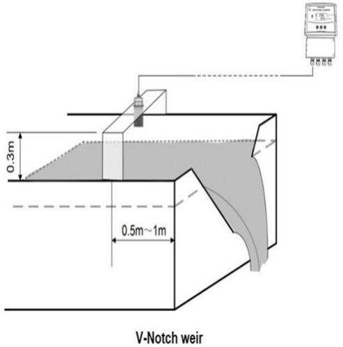
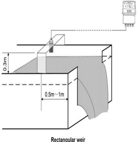
Open Channel Flow Meter is an economical solution for open channel measuring which measures level, flow rate and total volume of water flowing through weirs and flumes. The meter includes a non-contact ultrasonic level sensor to detect the water level and then calculates the flow rate and volume using the Manning equation and characteristics of the channel.
Advantages
Open Channel Flow Meter Advantages and Disadvantages
Economical and reliable. The accuracy of change in level is 1 mm. Suitable for a variety of weirs and flumes, Parshall flumes (ISO), V-Notch weirs, Rectangular weirs(With or Without End Contractions) and custom Formula type weir; Displays flow rate in L/S , M3/h or M3/min; Clear display with Graphical LCD(with backlight) ; The cable length between probe and host up to 1000m; The probe with leak-proof structure and IP68 protect grade; Chemically resistant probe materials for maximum application flexibility; Provided 4-20mA output and RS485 serial communication (MODBUS-RTU) output; Provided programmable 6 relays at most for alarms; Three button for programming easy configuration and operationopt.
Installation
Open channel flow meter Hints for probe mounting
1. The probe can be supplied as standard or with a screw nut or with an ordered flange.
2. For applications requiring chemical compatibility the probe is available fully enclosed in PTFE.
3. The use of metallic fittings or flanges is not recommended.
4. For exposed or sunny locations a protective hood is recommended.
5. Make sure that the probe is mounted perpendicular to the monitored surface and ideally, at least 0.25 meters above it, because the probe cannot get response in the blind zone.
6. The probe has a 10 inclusive conical beam angel at 3 db and must be mounted with a clear unobstructed sight of the liquid to be measured. But smooth vertical sidewalls weir tank will not cause false signals.
7. The probe must be mounted upstream of the flume or weir.
8. Do not over-tighten the bolts on flange.
9. The stilling well can be used when there is volatility in the water or needs to improve the accuracy of level measurement. The still well connect with the bottom of the weir or flume, and the probe measures the level in the well.
10. When install to the cold area, should choose the lengthen sensor and make the sensor extend into the container, shun frost and icing.
11. For Parshall flume, the probe should be installed in a position the 2/3 contraction away from the throat.
12. For V-Notch weir and rectangular weir, the probe should be installed on the upstream side, the maximum water depths over the weir and 34 times away from the weir plate.
CBRO handheld ultrasonic flow meter realizes non-contact measurement of liquid flow. Install the sensor on the outer wall of the pipeline to complete the flow measurement. It has the characteristics of small size. Convenient carrying and accurate measurement. Handheld Ultrasonic Flow meter Principle Working: Time-transit measurement principle is adopted, the signal transmitted by one flow meter transducer passes through the pipe wall, the medium, the second transducer also transmits the signal received by the first transducer. The influence of the medium flow rate, there is a time difference, flow value Q can be obtained.
Application
Handheld Ultrasonic Flow Meter Applications
This flow meter is widely used in tap water, heating, water conservancy, metallurgy chemical, machinery, energy and other industries. It can be used for production monitoring, flow verification, temporary detection, flow inspection, water meter balance debugging, heating network balance debugging, energy-saving monitoring, and it is a necessary tool and meter for timely flow detection.
Installation
Handheld ultrasonic flow meter installation requirements
The state of the pipeline for measuring the flow will greatly affect the measurement accuracy, the detector installation location should be selected in a place that meets the following conditions:
1. It must be ensured that the straight pipe section where the probe is installed is: 10D on the upstream side(D is the pipe diameter), 5D or more on the downstream side, and there must be no factors that disturb the fluid(such as pumps, valves, throttles, etc.) in the 30D on the upstream side. And try to avoid the unevenness and welding position of the pipeline under test.
2. The pipeline is always full of liquid, and the fluid should not contain bubbles or other foreign objects. For horizontal pipelines, install the detector within ±45°of the horizontal centerline. Try to choose the horizontal centerline position.
3. When install the ultrasonic flow meter, need to input these parameters: pipe material, pipe wall thickness and pipe diameter. Fulid type, whether it contains impurities, bubbles, and whether the tube is full.
CBRO Liquid Turbine Flow Meter is internally developed and perfected by CBRO Instrument. Over the years, CBRO Liquid Turbine Flow Meter has been commissioned in many parts of the world, received praise from end-users and industrial leaders. CBRO Instrument Turbine Flow Meter offers two accuracy classes, 0.5%R and 0.2%R. Its simple structure allows a small pressure loss and virtually no maintenance requirements. Our users can select the preferred converter type depending on the commissioning environment.
Advantages :-
Liquid Turbine Flow Meter Advantages and Disadvantages
CBRO strives to provide high-quality products with economical cost.
CBRO Liquid Turbine Flow Meter applies to viscous fluids, non-conductive fluids, solvents, liquefied gases and high-pressure applications.
CBRO Instrument Liquid Turbine Flow Meter provides high accuracy of 0.2% R and a wide range of applications to non-conductive liquids, such as fuel oil, ultrapure water and gasoline. These make the turbine meter more popular compare to Electromagnetic Flow Meter in the oil industry, purifying process and distilleries.
The Flange type connection Turbine Flow Meter is known for its application in oil & gas industry. It is compatibility with high temperature/pressure pipe and high durability makes it the most popular flow instrument in oil and gas industry.
Application :-
Liquid Turbine Flow Meter Applications
CBRO Instrument Liquid Turbine Flow Meters offers both standard SS304 body and SS316 body. Because of its wide working temperature and pressure range, it is capable of measuring various mediums and commissioning into extreme working conditions.
CBRO Instrument Liquid Flow Turbine Meters are popular in the Oil & Gas industry, Chemical industry, and Water industry. The Flange connection version is compatible with High pressure/temperature commission sites. It is the most popular meter in upstream oil production and transportation, off-shore exploration, water supply, and much more.
Due to its high accuracy and fast response time, CBRO Instrument Liquid Turbine is often integrated into the Industrial Internet of Things, together with valves and pumps to achieve smart process control, for example, solvents batching, blending, storage and off-loading systems. Kindly contact our sales engineers if there are questions related to integrating CBRO Liquid Turbine Meters into your existing plant IOT.
Application Areas :-
Various Modes :-
Features :-
Important Tips
Electro-magnetic flow meters suffer from the drawback that the flowing media or liquid must be conductive in nature, whereas such is not the case with Turbine Flow meter, which provides excellent performance even in non-conductive liquids like kerosene, petroleum, vegetable oil etc
Installation :-
Liquid Turbine Flow Meter Installation and Maintenance
Before the installation, it is crucial to communicate with our sales engineers regarding the working conditions and medium the meter designs to measure.
The installation of the Q&T Flange Type Liquid Turbine Flow Meter involves minimal effort. During installation, the users will need bolts, nuts, washers and appropriate tools for installation.
The user needs to keep in mind these three factors while carrying out the installation.
1. There should be at least ten pipe diameter lengths of straight pipe upstream of the Turbine Meter and five pipe diameter length of straight pipe length downstream of the Turbine Meter, with the same nominal diameter size.
2. Valves and Throttling devices needed to install downstream of the flow meter.
3. The arrow indicated on the meter body is the same as the actual flow.
If there are specific questions regarding the installation of the Q&T Instrument Turbine Meter, kindly contact our sales engineers for assistance.
Electromagnetic water meter is a kind of instrument for measuring the volume flow of conductive liquid based on Faraday’s principle of electromagnetic induction. It has the characteristics of wide range, low initial flow, low pressure loss, real-time measurement, cumulative measurement, bi-direction measurement, etc. It mainly uses DMA zoning, online monitoring, water loss analysis and statistical settlement of water supply mains.
Advantages :-
1 No blocking parts inside of measuring tube, low pressure loss and low requirements for straight pipeline.
2 Variable diameter design, improve measurement accuracy and sensitivity, reduce excitation power consumption.
3 Select suitable electrodes and liner, with good corrosion resistance and wear resistance.
4 Full electronic design, strong anti-interference ability, reliable measurement, high accuracy, wide flow range.
Application :-
Electromagnetic water meter is a metering instrument specially designed for the actual requirements of water supply enterprises, specially designed for water industry, which can optimize water supply and ensure accurate water trade measurement and settlement. Practice has proved that electromagnetic water meter is the ideal choice to solve the measurement contradiction of large water users. In addition, electromagnetic water meters are widely used in chemical industry, environmental protection, metallurgy, medicine, paper making, water supply and drainage and other industrial technology and management departments.
Installation :-
Installation environment selection
1. Stay away from devices with strong electromagnetic fields. Such as large motor, large transformer, large frequency conversion equipment.
2. The installation site should not have strong vibration, and the ambient temperature does not change much.
3. Convenient for installation and maintenance.
Selection of installation location
1. The flow direction mark on the sensor must be consistent with the flow direction of the measured medium in the pipeline.
2. The installation position must ensure that the measuring tube is always filled with the measured medium.
3. Select the place where the fluid flow pulse is small, that is, it should be far away from the water pump and local resistance parts (valves, elbows, etc.)
4. When measuring the two-phase fluid, choose the place which is not easy to cause phase separation.
5. Avoid installation in the area with negative pressure in the tube.
6. When the measured medium easily causes the electrode and the inner wall of the measuring tube to adhere to and scale, it is recommended that the flow rate in the measuring tube be no less than 2m/s. At this time, a tapered tube slightly smaller than the process tube can be used. In order to clean the electrode and measuring tube without interrupting the flow in the process tube, the sensor can be installed in parallel with a cleaning port.
Wafer electromagnetic flow meter is a kind of volume flow meter. It uses a new generation of special high-quality lining technology and a special mirror-polished PFA lining, which is especially suitable for the measurement of viscous pulp and gypsum slurry. Its detachable electrode makes maintenance more convenient. Principle of Wafer electromagnetic flow meter : The product is based on Faraday’s law of electromagnetic induction, conductance greater than 20 μS/cm volume of conductive liquid flow. In addition to measuring the general volume of conductive liquid flow, but also can be used to measure strong acid, alkali and other strong corrosive liquids and mud, pulp, etc.
Advantages :-
Wafer Electromagnetic Flow Meter Advantages and Disadvantages
Wafer electromagnetic flow meter has short body, it can be installed in narrow areas such as well, ditch, irrigation pipe, etc.
It matches all flanges like ANSI, DIN, JIS, etc. So if you don’t know the flange standards, you can choose this type.
And wafer electromagnetic flow meter adopts harmless and durable stainless steel as raw material(SS304 or SS316), so it can be used for drinking water, underground water, etc. For food grade measurement, we suggest customer use SS316 material.
Wafer electromagnetic flow meter is easy to delivery, save your freight fee. Not only its body is short and thin, but its weight is also very light.
Application
Wafer Electromagnetic Flow Meter Application
Electromagnetic flow meter is widely used in water treatment, food industry, pharmaceutical, petrochemical, paper mill, chemical monitoring etc.
In the metallurgical industry, it is often used to control the flow of cooling water for continuous steel casting, continuous steel rolling, and steel-making electric furnaces;
In the field of water supply and drainage in public utilities, electromagnetic flow meters are often used for the transfer measurement of finished product water and raw water in water plants;
In the pulp process of the paper industry, electromagnetic flow meters are involved in the measurement of the flow of grinding pulp, water, acid, and alkali;
In the coal industry, measuring coal washing and pipeline hydraulic conveying coal slurry.
For food and beverage industries, it is used for beer and beverage filling measurement.
For chemical and petrochemical industries, it is used to measure corrosive liquids, such as acids and alkalis etc.
Installation :-
Wafer Electromagnetic Flow Meter Installation & Maintainance
1. Installation
First of all, we need choose a pair of matching flanges. Then connect the flow meter with pipeline.
Wafer electromagnetic flow meter should be installed correctly to ensure good measurement. Normally we need leave 10D(10 times of diameter) straight pipe distance before wafer electromagnetic flow meter and 5D behind wafer electromagnetic flow meter.
And try to avoid elbow/valve/pump or other device which will influent the flow speed. If the distance is not enough, then please install flow meter according to follow picture.
2. Maintenance
Routine maintenance: only need to make periodic visual inspections of the instrument, check the environment around the instrument, remove dust and dirt, ensure that no water and other substances enter, check whether the wiring is in good condition, and check whether there are newly installed strong electromagnetic field equipment or newly installed wires near the instrument Cross-instrument. If the measuring medium easily contaminates the electrode or deposits in the measuring tube wall, it should be cleaned and cleaned regularly.
Battery-powered magnetic flow meter can be used in remote area where don’t have power grid . It is widely used for all conductive liquids in every industry, such as water, acid, alkali, milk, slurry etc. Since founded in 2005, CBRO has been focused in magnetic flow meter manufacturing for more than 15 years. More than 600 thousand mag meters had been provided to clients all over the world for different work conditions.
Advantages :-
Battery Powered Electromagnetic Flow Meter Advantages and Disadvantages
has a long life span, standard battery can work for 3-6 years, determined by the excitation current
2.Dual power supply: it’s equipped with external power supply interface, which
can be powered by external 12-24vdc power supply, enabling users to have a variety of power options;
3. Multiple network interfaces: W803 has GPRS, RS485, HART and other network communication for users;
4.Multiple work mode: W803E has ‘Flow Only’ mode, ‘Flow + Pressure’ mode, ‘Flow + Temperature’ mode for users.
Application :-
Electromagnetic flow meter is widely used in water treatment, food industry, pharmaceutical, petrochemical, paper mill, chemical monitoring etc.
In the metallurgical industry, it is often used to control the flow of cooling water for continuous steel casting, continuous steel rolling, and steel-making electric furnaces; In the field of water supply and drainage in public utilities, electromagnetic flow meters are often used for the transfer measurement of finished product water and raw water in water plants; In the pulp process of the paper industry, electromagnetic flow meters are involved in the measurement of the flow of grinding pulp, water, acid, and alkali; In the coal industry, measuring coal washing and pipeline hydraulic conveying coal slurry.
For food and beverage industries, it is used for beer and beverage filling measurement.
For chemical and petrochemical industries, it is used to measure corrosive liquids, such as acids and alkalis etc.
Installation :-
Battery Powered Electromagnetic Flow Meter Installation Requirement
In order to obtain a stable and accurate flow measurement, it is very important that the flow meter is installed correctly in the pipe system.
Do not install the meter near equipment that produces electrical interference such as electric motors, transformers, variable frequency, power cables etc.
Avoid locations with pipe vibrations for example pumps.
Do not install the meter close to pipeline valves, fittings or impediments which can cause flow disturbances.
Place the meter where there is enough access for installation and maintenance tasks.
Tri-clamp electromagnetic flow meter is a kind of volume flow meter. Tri-clamp electromagnetic flow meter is made of stainless steel, which can be easily disassembled and cleaned quickly, so it is not easily polluted during use, and can effectively prevent the accumulation of measuring fluid residues in the measuring tube.
Wafer electromagnetic flow meter working: The product is based on Faraday’s law of electromagnetic induction, used to measure the conductance greater than 20 μS/cm volume of conductive liquid flow. In addition to measuring the general volume of conductive liquid flow, but also can be used to measure strong acid, alkali and other strong corrosive liquids and mud, pulp, etc.
Advantages :-
Tri-clamp Electromagnetic Flow Meter Advantages and Disadvantages:
Tri-clamp electromagnetic flow meter is easy to be installed and dismantled. It adopts Harmless food grade stainless steel as raw material, so it can touch with food directly.
Stainless steel material has long service life, and SS316 is a kind of anti-corrosive stainless steel, so it can be used to measure most of drinks. It has small size and light weight so it can save your freight fee.
It has multiple output signals for choose. It has current output and pulse output for connecting with PLC or other devices. And you can also read flow measurement by RS485/HART/Profibus.
Application
Tri-clamp electromagnetic flow meter is mainly used in drinking water, milk, ground water, beer, wine, jam, juice and other food & drink industries. It is also widely used in paper pulp, gypsum slurry because it can be cleaned easily.
It adopts harmless stainless steel material so it can measure food directly. And it can withstand high temperature steam disinfection.
Local display type can withstand -20-60 deg C temperature, remote display can withstand -20-120 deg C
Flange vortex flow meter is used in numerous branches of industry to measure the volume flow of liquids, gases and steam. Applications in the chemicals and petrochemicals industries, for example, in power generation and heat-supply systems involve widely differing fluids: saturated steam, superheated steam, compressed air, nitrogen, liquefied gases, flue gases, carbon dioxide, fully demineralized water, solvents, heat-transfer oils, boiler feedwater, condensate, etc.
Advantages :-
Vortex flow meter advantages and disadvantages
Vortex flow meter body is robust and universally applicable for liquids, gases and steam, optimized for steam applications. CBRO Vortex flow meter adopt Japan OVAL technology and design. To protect the sensor, CBRO vortex flow meter choose embedded sensor, with 4 piezo-electric crystal encapsulated inside the sensor, which is our own patent. There is no moving parts, no abrasion, non-wearing parts inside the vortex flow meter sensor, fully welded SS304 body (SS316 selectable). With patented sensor and flow sensor body, CBRO vortex flow meter could eliminate drift & vibration influence from great aspect in the working site while compare with other flow meters.
Application :-
Vortex flow meter application
Vortex flow meter is professional in measuring non-conductive liquids, gases, saturated and superheated steam, especially for steam measurement trade settlement.
Except work as flow meter, vortex flow meter can also work as heat meter to measure the Gross/net heat of steam and hot water.
Vortex flow meter usually monitor the compressor output and evaluation of Free Air Delivery (FAD)
There has lots of Industrial gases, such as natural gas, nitrogen gas, liquefied gases, flue gases, carbon dioxide etc, all could use vortex flow meter.
In many factories, compressed air monitoring is very important, vortex flow meter also could use for process control. Besides the different gases measurement, vortex flow meter could also used for light oil or any purified watersuch as thermal oils, Desalinated water, demineralized water, RO water, boiler feed water, condensate water etc.
In the Chemicals and petrochemicals industries, there also has lots of gases or liquid could use vortex flow meter for monitoring.
Installation :-
1. The installation of vortex flow meter has higher requirements, to guarantee the better accuracy and working properly. Vortex flow meter installation should keep away from the electric motors, big frequency converter, power cable, transformers, etc.
Do not install in the position where there has bends, valves, fittings, pumps etc, which could cause flow disturbances and influence the measurement.
The front straight pipe line and after straight pipe line should follow below suggestion.
2. Vortex Flow Meter Daily Maintenance
Regular cleaning: The probe is an important structure of the vortex flowmeter. If the detection hole of the probe is blocked, or is entangled or wrapped by other objects, it will affect the normal measurement, resulting in inaccurate results;
Moisture-proof treatment: most of the probes have not undergone moisture-proof treatment. If the use environment is relatively humid or is not dried after cleaning, the performance of the vortex flow meter will be affected to a certain extent, resulting in poor operation;
Minimize external interference: strictly check the grounding and shielding conditions of the flow meter to ensure the accuracy of the flow meter measurement;
Avoid vibration: There are some parts inside the vortex flowmeter. If strong vibration occurs, it will cause internal deformation or fracture. At the same time, avoid the inflow of corrosive liquid.