Our Products
Our Complete range of products are Settable on off Long Duration Timer Circuit, Earthquake and Vibration Alarm, Listening Bug Circuit, Shadow Alarm and Infrared Burglar Alarm Circuit.

The Police Ambulance Siren Circuit uses two No. 555 ICs and generates police/ ambulance siren. Here, is the circuit diagram of a police siren based on NE555 timer IC. The circuit uses two NE555 timers ICs and each of them are wired as astable multi vibrator. The circuit can be powered from anything between 6 to 12V DC and is fairly loud. By connecting an additional power amplifier at the output, you can further increase the loudness. IC1 is wired as a slow astable multi vibrator operating at around 20Hz @ 50% duty cycle and IC2 is wired as fast astable multi vibrator operating at around 600Hz.The output of first astable multi vibrator is connected to the control voltage input (pin5) of IC2. This makes the output of IC2 modulated by the output frequency of IC1, giving a siren effect. In simple words, the output frequency of IC2 is controlled by the output of IC1. The component arrangement is low frequency and extension of production low frequency is obtained from IC1 connected to astable multi vibrator circuit frequency is set by R1, C2 frequencies that are coming out of pin 6, 7 is about 20 Hz through the circuit of IC1, a division produce high-frequency input at Pin 5 will tone the origin of oscillator IC2 is the ripple of voltage from the output of IC1 frequency of IC2 is being set by R2, C3, which, if C3 value. It will be very low tone if C3 is less treble.

20 To 30 Sec. Voice Recording / Playback (APR9301) Circuit is a re-recordable single chip Voice recorder with non volatile memory that can store up to 20-30 seconds of message and comes with playback facility. APR9301 is an ideal IC for automatic answering machines, door phones, etc. This IC has data storage capacity and requires no software and microcontroller. The APR9301 provides high quality voice recording and played back up to 30 seconds. The IC requires minimum components to create a voice recorder. The IC has non-volatile flash memory technology with 100 K recording cycles and 100-year message retention capacity. The IC utilizes the Invox proprietary analog / multi level flash non-volatile memory cells that can store more than 256 voltage levels. It requires a single 6-volt supply and operates in 25 mA current.
Record Mode : The LED glows when the IC records the voice obtained through the Mic. A single voice message up to 20 seconds can be recorded. The IC remains in the recorded mode as long as the RecL pin 27 is grounded. Recoding will be terminated with the last memory when 20 seconds is over. The Speaker driver will automatically mutes in the recording mode. By changing the value of the OscR resistor R1 it is possible to increase the recording period as follows :
Playback Mode : By pressing the play back switch S2, the play mode starts from the beginning of the message. The input section will be muted during play back. After completing the Record or Play back function, the IC will enters into the standby mode. Press, switch S1 and speak through the Mic or record music. LED will glow in the recording mode. Open S1 after recording. Use a small condenser Mic Close S2. Recorded message will be heard from the speaker. Use a 2 inch 8 Ohms speaker. Power supply 6 Volt regulated supply or 6 volt battery.


Quizmaster Board is designed to be used in quiz shows. Quizmaster determines who is first to press an answer button, is a problem since more than one person may appear to have pressed the button at same instant of time. To differentiate between the minute time differences in between two persons pressing the buttons is almost impossible for human being.
Only electronic device can do it with accuracy and therefore our Quizmaster is very popular now days with growing competitions being arranged. The circuit given here helps to make students familiar with an interesting device and helps develop understanding and interest of electronics bedsides commercial utilization.
About the circuit :As shown in the diagram, the circuit is designed around ICs 4012 (NAND GATES) and 4013 (D Flip flop).
The IC 4012 which has two dual FF with SET and CLEAR inputs; is used to set/ reset FFs. When the competitor presses a button/push switch (say S1), the FF1 gets SET (Q = 1, Pin13) irrespective of D and clock inputs. However to avoid action by noise pulses, the D input and Clock input is connected to logic HI.
This action forces Q output to go HI and Q- (pin12) to go LO. Hi at Q output will force LED D1 to glow through driver transistor T1. The Q- output is connected to inputs of all NAND gates
(N2, N3, N4) in the remaining FF circuits. The NAND gate outputs are in turn connected to CLEAR input of FF ( FF2, FF3, and FF4). This will produce LO state at all other FF outputs (Q) by virtue of being cleared.
The circuit is reset after a round is finished before the next round is to be started. The reset switch S5 shown here forces one input of all.
When next time another button is pressed, the corresponding FF gets SET and all other FFs gets reset thus glowing another corresponding LED.
Thus with press of a push switch, corresponding LED glows and all others get inhibited. The circuit also has a common buzzer, which gives audio alarm when any of the LED glows so as to attract attention of viewers and judges. The common buzzer is activated by another set of transistors driven from same output of FFs. All the buzzer signals are ORed through D5 – D8. The circuit can be easily extended to more number of competitors. For each additional competitor/participant an extra FF and a NAND gates is required to be connected. These NAND gates can be Red and the same result can be obtained. To avoid possibility of interference on account of long length of wires , the low impedance of RC network connected to SET input has to be kept low .If such problem is faced , value of R1 –R8 can be reduced to 1k.

Wireless Listening Bug is used to listen to the voices of people sitting in the nearby room on fm radio. The circuit can detect both incoming and outgoing calls, SMS and video transmission even if the mobile phone is kept in the silent mode. The moment the bug detects RF transmission signal from an activated mobile phone, it starts sounding a beep alarm and the LED blinks. The alarm continues until the signal transmission ceases. An ordinary RF detector using tuned LC circuits is not suitable for detecting signals in the GHz frequency band used in mobile phones. The transmission frequency of mobile phones ranges from 0.9 to 3 GHz with a wavelength of 3.3 to 10 cm. This handy, pocket-size mobile transmission detector can sense the presence of an activated mobile phone from a distance of one and-a-half meters. So it can be used to prevent use of mobile phones in examination halls, confidential rooms, etc. It is also useful for detecting the use of mobile phone for spying and unauthorized video transmission. So a circuit detecting gigahertz signals is required for a mobile bug. Here the circuit uses a 0.22µF disk capacitor (C3) to capture the RF signals from the mobile phone. The lead length of the capacitor is fixed as 18 mm with a spacing of 8 mm between the leads to get the desired The disk capacitor along with the leads acts as a small gigahertz loop antenna to collect the RF signals from the mobile phone Op-amp IC CA3130 (IC1) is used in the circuit as a current-to-voltage converter with capacitor C3 connected between its inverting and non-inverting inputs. It is a CMOS version using gate-protected p-channel MOSFET transistors in the input to provide very high input impedance, very low input current and very high speed of performance. The output CMOS transistor is capable of swinging the output voltage to within 10 mV of either supply voltage terminal. This will upset the balanced input of IC1 and convert the current into the
corresponding output voltage. Capacitor C4 along with high-value resistor R1 keeps the non-inverting input stable for easy swing of the output to high state. Resistor R2 provides the discharge path for capacitor C4. Feedback resistor R3 makes the inverting input high when the output becomes high. Capacitor C5 (47pF) is connected across ‘strobe’ (pin 8) and ‘null’ inputs (pin 1) of IC1 for phase compensation and gain control to optimize the frequency response. When the mobile phone signal is detected by C3, the output of IC1 becomes high and low alternately according to the frequency of the signal as indicated by LED1. This triggers monostable timer IC2 through capacitor C7. Capacitor C6 maintains the base bias of transistor T1 for fast switching action. The low-value timing components R6 and C9 produce very short time delay to avoid audio nuisance. Assemble the circuit on a general purpose PCB as compact as possible and enclose in a small box like junk mobile case. As mentioned earlier, capacitor C3 should have a lead length of 18 mm with lead spacing of 8 mm. Carefully solder the capacitor in standing position with equal spacing of the leads. The response can be optimized by trimming the lead length of C3 for the desired frequency. You may use a short telescopic type antenna. Use the miniature 12V battery of a remote control and a small buzzer to make the gadget pocket-size. The unit will give the warning indication if someone uses mobile phone within a radius of 1.5 meters.

Infrared Communication System is a device for I/R audio communication through transmitter and receiver up to a distance 10 meters. Infrared remote control devices are abundant in today's gadget-filled world. From the television and video recorder, through the Hi-Fi and on to the garage door that thankfully opens remotely on a rainy day, a remote controller of one form or another is never far from reach. Why use infrared light to send the control signals? Two reasons in particular stand out. The first is that the diodes used to emit infrared light are quite inexpensive and readily available. The second is the fact that infrared light is at a wavelength outside of the spectrum of visible light – so we can point and shoot our controllers and not get blinded in the process!
So how exactly does infrared remote control work? At the most basic level, the remote controller contains a transmitter circuit, part of which will be an Infrared Light Emitting Diode (IRLED). When a key is pressed on the controller, the command is sent as an IR signal to the device which you are aiming the controller at. The device being controlled will have a receiver circuit, part of which will be a photodiode with which to detect the IR signal and convert it into an electric current.
That's a very simplistic view of IR RC communications. However, when you factor in background infrared "noise" emitted by other heat-generating objects and multiple IR remote-controlled devices located in close proximity to each other, things quickly become more complicated. With simple infrared light, there is now potential for the command not getting to the receiver at all, let alone the receiver in the intended device. Using this circuit, audio musical notes can be generated and heard up to a distance of 10 meters. The circuit can be divided into two parts: IR music transmitter and receiver. The IR music transmitter works off a 9V battery, while the IR music receiver works off regulated 9V to 12V. Fig. 1 shows the circuit of the IR music transmitter. It uses popular melody generator IC UM66 (IC1) that can continuously generate musical tones. The output of IC1 is fed to the IR driver stage (built across the transistors T1 and T2) to get the maximum range. Here the red LED (D3) flickers according to the musical tones generated by UM66 IC, indicating modulation. IR LED D1 and LED D2 are infrared transmitting LEDs. For maximum sound transmission these should be oriented towards IR phototransistor L14F1 (T3).The IR music receiver uses popular op-amp IC µA741 and audio-frequency amplifier IC LM386 along with phototransistor L14F1 and some discrete components (Fig. 2). The melody generated by IC UM66 is transmitted through IR LEDs, received by phototransistor T3 and fed to pin 2 of IC µA741 (IC2). Its gain can be varied using potmeter VR1. The output of IC µA741 is fed to IC LM386 (IC3) via capacitor C5 and potmeter VR2. The melody produced is heard through the receiver’s loudspeaker. Potmeter VR2 is used to control the volume of loudspeaker LS1 (8-ohm, 1W). Switching off the power supply stops melody generation.

The Clap Operated Staircase Light is a useful device for staircase light, which can be turned ‘ON’ by clap & ‘Off’ as per delay setting. The Clap Operated Staircase Light is a solution for common habit of switching the light on and forgetting the same. Stairways, corridors or small indoor passages often tend to be dark throughout the day irrespective of the outdoor ambient light conditions. Therefore keeping such passages illuminated all the time becomes imperative, however this leads to unnecessary wastage of electricity.
This 9-12V battery-operated circuit triggers an Lights on when a sound is detected. It can also be used staircase light delay ON time setup as per your choice, which is as per person taking time to up or down period to complete staircase distance. The circuit has an ordinary condenser microphone MIC1 as a sound sensor. Sensitivity of this microphone can be changed to some extent by changing the value of the bias resistor R1. When the circuit is powered by a 9-12V battery supply to the circuit, transistor T1 acts as pre amplifier and T2 is again amplification the week signal of the mic and condenser C3 charge /discharge pulse fed to the IC1 of pin 2. This IC1 is in monostable mode the time starts up to the capacitor C5 will be discharge, and output pin 3 of IC 1 get firing the transistor T3 conduct, hence relay will be 'ON' and start the light / Bulb through relay in the series of the mains 220v will be 'ON'. The time period can be adjust by setting to VR2 Preset. VR1& R9 use for pull-up resistance for adjusting the avoid chattering the pin 2 of IC1.

The Whistle Responder beeps when it hears your whistle and this amazing invention is priced at a meager Rs 350/-. Some 20 years ago it was common to see small key-holders emitting an intermittent beep for a couple of seconds after its owner whistled. These devices contained a special purpose IC and therefore were not suited to home construction. The present circuit is designed around a general purpose hex-inverter CMos IC and, using miniature components and 9V batteries can be enclosed in a box. It is primarily a gadget, but everyone will be able to find suitable applications.
About the circuit :This device beeps intermittently for about two seconds when a person in a range of around 5 meters emits a whistle. The first two inverters contained in IC1 are used as audio amplifiers.IC1'A' amplifies consistently the signal picked-up by the small electret-microphone and IC1'B' acts as a band-pass filter, its frequency being centered at about 1.8KHz. The filter is required in order to select a specific frequency, the whistle's one, stopping other frequencies that would cause undesired beeper operation. IC1'C' is wired as a Schmitt trigger, squaring the incoming audio signal. IC1'D' is a 2 second-delay monostable driving the astable formed by IC1'E' & IC1'F'. This oscillator generates a 3 to 5Hz square wave feeding Q1 and Buzzer (BZ), thus providing intermittent beeper operation.

The +5v To +15v Regulated Power Supply Circuit gives regulated output of +5V to +15V and is available at a price of Rs 240/-. Integrated circuit voltage regulators are available in a range of output voltages and usually feature internal fold-back current limiting as well as thermal shut-down. The most popular series of fixed positive voltage regulators employ 78XX series voltage regulator. The circuit described here also uses 78XX regulator to give the fixed DC output voltage as +5V, +9V, +12V and +15V depends on type of regulator IC. The IC number and transformer rating for different output voltages are given in table.
About the Circuit :As shown in the circuit diagram, AC input is given through transformer. The transformer rating depends on the output DC voltage as shown in the table. The AC output voltage obtained from the transformer, is rectified through bridge rectifier designed using four diodes D1 to D4. Capacitors C3 and C4 are used to filter the AC signal. The rectified filtered output is given to positive regulator IC1. The output of IC1 gives the fixed DC voltage depending on the voltage capability. This output is again filtered through capacitor C5. LED D5 glows, which indicates output power.

The Dual Power Supply Circuit gives regulated Dual output of ±5V to ±15V and is available at a reasonable price of Rs 380/-. One often realizes the need for power supplies, which provide dual positive and negative output rails. This is particularly true with circuits, which contain operational amplifiers. Such devices require closely regulated supply rails of typically ±5V, ±9V, ±12V or ±15V. Integrated circuit voltage regulators are available in a range of output voltages and usually feature internal fold-back current limiting as well as thermal shut-down. A simple method of meeting such a requirement is shown in figure. Here two fixed voltage regulators of opposite polarity, are used in conjunction with a dual secondary transformer and single bridge rectifier. The current rating of the regulators should be greater than, or equal to, the maximum load current. Circuits which are solely based on operational amplifiers rarely require supply currents in excess of 100mA and thus 78XX/79XX series regulators will usually be adequate. The IC number and transformer rating for different output voltages are given in table.
About the Circuit :As shown in the circuit diagram, AC input is given through transformer. The transformer rating depends on the output DC voltage as shown in the table. The AC output voltage obtained from the transformer, is rectified through bridge rectifier designed using four diodes D1 to D4. Capacitors C1 and C2 are used to filter the AC signal. The rectified filtered output is given to regulator IC1 and IC2. The output of IC1 and IC2 gives the fixed DC voltage depending on the voltage capability. This output is again filtered through capacitor C5 and C6. LED D5 and D6 glows, which indicates positive and negative output.

Cordless FM Mike can effectively achieve 10-20mtr receptions from transmitters. You can listen your sound in any FM radio (Receiver) by tuning radio frequency in between 88 to 108 MHz. This FM circuit uses a medium power VHF oscillator built around BC547 transistor. The BC series transistors frequency is 200-250MHz.These can oscillate well in VHF range.
Audio is picked up from the room by an condenser microphone and transmit by T1. 10K resistor (R1) supplies the bias voltage for the microphone. A varicap based circuit is used for good quality frequency modulation. Operational frequency can be altered by adjusting spacing of coil L1. L1, C4 from LC circuit to produce oscillations. Coil L1 consists of 20 SWG wire, space wound air core. Antenna tap is taken at one turn from bottom end. By using 7cms wire arial, range up to 10 meters may be expected. The range can be extended by using a multi-element ground plane antenna. Output power of the transmitter can be raised by lowering value of resistor R5 connected between emitter of transistor T1 and ground to, say 27 to 39 ohms.

We bring forth L293D Motor Driver for driving DC motors and is ideal for robotics applications. L293D Motor Driver is a medium power motor driver perfect for driving DC motors and Stepper motors. L293D Motor Driver uses the popular L293D H-bridge motor driver IC. It can drive 4 DC motors in one direction, or drive 2 DC motors in both the directions with speed control. The driver greatly simplifies and increases the ease with which you may control motors, relays, etc. from microcontrollers. L293D Motor Driver can drive motors up to 12 V with a total DC current of up to 600mA
Detail :
Package Content : L293D motor driver board

line follower robots are a popular beginner’s choice. It’s the most basic example of adding small intelligence to a robot, but it’s actually the designer’s intelligence! after reading this documentation and going through the assembly video from our website, you will be playing with the one shown above. Moreover you can make line follower robot modular so that it can be easily modified in future. the main electronics and mechanical components that will be used in making this line follower robot are two sensors made using ir leds, a atmega8 based microcontroller board including motor driver circuitry, acrylic chassis set, two bo motors and wheels and battery holder.
features :

Robotic Arm Kit is a Degree of Freedom Robotic Arm: Base rotation, Shoulder, Elbow, Gripper. Available with IR Remote and RF Remote, Robotic Arm Kit operates from 9-12V DC and is also available in battery operated mode which is optional.
Features :

An Obstacle Avoiding Robot is an intelligent device, which can automatically sense and overcome obstacles on its path. It’s the most basic example of adding small intelligence to a robot, but it’s actually the designer’s intelligence! After reading this documentation and going through the assembly video from our website, you will be playing with the one shown above. Moreover you can make an Obstacle Avoiding Robot modular so that it can be easily modified in future. The main electronics and mechanical components that will be used in making an Obstacle Avoiding Robot are two sensors made using TSOP and IR LEDs, an ATmega8 based microcontroller board including motor driver circuitry, acrylic chassis set, two BO motors and wheels and battery holder.
Features :

a sound activated robot is an intelligent device, which can be programmed to act upon noise. A sound activated robot is the most basic example of adding small intelligence to a robot, but it’s actually the designer’s intelligence! after reading this documentation and going through the assembly video from our website, you will be playing with the one shown above. Moreover you can make it modular so that it can be easily modified in future. the main electronics and mechanical components that will be used in making this sound activated robot are sound sensor made using condenser microphone, an atmega8 based microcontroller board including motor driver circuitry, acrylic chassis set, two bo motors and wheels and battery holder.
features :

DTMF Controlled Robot uses the DTMF module and can be controlled from mobile using an Android phone app. After reading this documentation and going through the assembly video from our website, you will be playing with the one shown above. Moreover, you can make DTMF Controlled Robot modular so that it can be easily modified in future. The main electronics and mechanical components that will be used in making this DTMF Controlled Robot are DTMF Module, an ATmega8 based microcontroller board including motor driver circuitry, acrylic chassis set, two BO motors and wheels and battery holder.
Features :

we are offering bluetooth controlled robot uses the bluetooth module and can be controlled from the pc using a master bluetooth or using the bluetooth of an android phone via an app. After reading this documentation and going through the assembly video from our website, you will be playing with the one shown above. Moreover you can make a bluetooth controlled robot modular so that it can be easily modified in future. the main electronics and mechanical components that will be used in making this bluetooth controlled robot are bluetooth module, an atmega8 based microcontroller board including motor driver circuitry, acrylic chassis set, two bo motors and wheels and battery holder.
features :

Areduino Serial + Atmega 8 is a basic board that uses RS232 as an interface to a computer for programming or communication. It has 14 digital inputoutput pins (out of which 6 can be used as PWM outputs), 6 analog inputs, a 16 MHz crystal oscillator, a DB9 connection, a power jack, an ICSP header, and a reset button. Areduino Serial + Atmega contains everything needed to support the microcontroller; simply connect it to a computer with a Serial cable and power it with a AC to DC adapter or battery to get started. Areduino Serial + Atmega board comes fully assembled and tested with ATmega8 pre-loaded with boot loader.
Detail:

We are offering areduino usb + atmega 8.areduino usb + atmega 8 board is a microcontroller board based on the atmega8. Areduino usb + atmega 8 connects to the computer with a standard usb cable and contains everything else you need to program and use the board and has 14 digital inputoutput pins (of which 6 can be used as pwm outputs), 6 analog inputs, a 16 mhz crystal oscillator, a usb connection, a power jack, an icsp header, and a reset button. Areduino usb + atmega 8 contains everything needed to support the microcontroller; simply connect it to a computer with a usb cable or power it with a ac to dc adapter or battery to get started.
Detail :

we are offering areduino usb + atmega 328. areduino usb + atmega 328 board is a microcontroller board based on the atmega328. it connects to the computer with a standard usb cable and contains everything else you need to program and use the board. areduino usb + atmega 328 has 14 digital inputoutput pins (of which 6 can be used as pwm outputs), 6 analog inputs, a 16 mhz crystal oscillator, a usb connection, a power jack, an icsp header, and a reset button. areduino usb + atmega 328 contains everything needed to support the microcontroller; simply connect it to a computer with a usb cable or power it with a ac to dc adapter or battery to get started.
Detail :

We are offering Bcd to 7 Segment Display Circuit. Introduction : We see alphabets and numbers on many electronic machines in the market and public places. Seven segment display is now a days so popular that no electronic indicator can do without it .Ever gadget designer should learn about it. To display any number in English we require seven segment display. The drivers for driving these displays are abundantly available. As well as decoders from binary to seven segment code are also available. With the help of these decoders and drivers we can incorporate these display in any system where numbers are to be displayed. About the circuit : The IC 7447 is a decoder driver for seven-segment display, common anode CA type. It converts BCD code to seven-segment code and drives each segment of LED in seven segments LED display. Only current limiting resistances are required to be used in each segment. The seven segment displays fall in two categories of the CA (common anode) and CC (common cathode). 7- segment LEDs also have 8th segment, called decimal point. Thus it has 8 LEDs inside one body and have normally 10 pins . Two pins are allotted for common and 8 for segments (a to f and dp). CA has all anodes connected together, brought out as common pin and cathodes are available individually at terminal pins. Similarly in CC, all cathodes are connected together, brought out as common pin and anodes are available individually. When we need to glow a particular segment , we must pull it down by driving the individual pin low. Exactly same thing happens when we feed BCD code at input of 7447. It converts BCD code to seven segments as shown here in the table. The circuit here outputs the desired outputs i.e. Hi at those terminals which are required to glow as per the BCD input given to it. Besides these functions, the decoderdriver IC has additional function pins like LT, RBI and BIBRO LT (pin 3) when pulled Low shall lit all segments. This is provided to check all display segments for their functionality. RBI (pin 5) when low blanks the display only when input is BCD zero. BIBRO (pin 4) when pulled low shall put off all segments irrespective of input logic levels. This is useful when leading zero blanking is to be used to save power or control intensity. Since it is not totem pole output and has only a resistive pull up, it acts as input and output both. When used as input it can be forced low because of resistive pull up provided internally. To achieve leading zero blanking of displays in a multi digit display, RBI pin of a most significant decoder is connected to ground, and its BIRBO pin (which becomes low)is connected to next lower order decoder and thus cascading all will achieve leading zero blanking. For better understanding and grasp of the decoder and display function, the PCB is provided with facility to connect miniature toggle switches for applying individual logic signal (H & L) to all BCD inputs. This facility can be useful to practice for beginners. IC2 ( 7805) is a 5- v regulator provided to supply power to the IC 7447 and to display. Rectified DC filtered Input to this circuit can be between 8.5 to 12 volts. The decimal to BCD table and truth table for decoder are provided with literature.

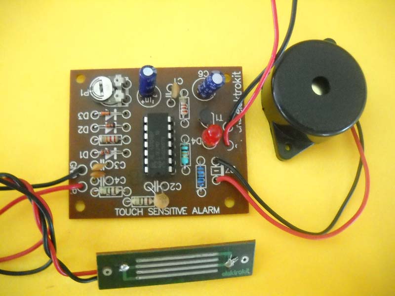
Touch Sensitive Musical Bell Circuit gives a different melody sound for every touch. This Touch Sensitive Musical Bell generates different musical tones every time the plate is touched. If the plate is touched for more than two seconds, it gives a sound (beep-beep) different from the musical tone. Musical tune is produced after removal of the hand touching the plate. Only a few additional components are required to achieve excellent results.
About the Circuit :The heart of the circuit is a musical tone generator IC APM993D (IC1). This is a programmed 1024 note ROM memory IC, which has inbuilt oscillator and tone generator. Touch plate is connected to base of transistor T1. When the plate is touched, T1 conducts and IC1gets triggered. Hence, it generates a musical tone. The output at pin 14 of IC is driven by transistors T2 in turn drives 8W Loudspeaker. Care should be taken that battery supply should not be greater than 3V.

Three Tune Musical Bell Circuit is a simple and low cost melody project. The UM 66T series are CMOS LS is designed for use in doorbell, telephone and toy applications. The Three Tune Musical Bell is a chip ROM programmed for musical performance produced by CMOS technology. It results in very low power consumption, since the UM 66T series include oscillating and mode selection circuit, a compact melody module can be constructed with only a few additional components.
About the circuit :The circuit uses UM 66T having 64 note ROM memory, which is capable to store three different tunes. The supply is given to IC through a switch S1. When the switch S1 is pressed, it will on the IC. The output of IC is in terms of sound. But, this signal is not enough to drive the speaker, so transistor T1 is used for amplifying the signal and to drive the speaker. Capacitor C1 is used as a filter capacitor. The power consumption of circuit is very low. It will work on supply of 3 volt.

This Multi-Tone Siren Circuit enables the users to select Police, Ambulance, and Fire & Staccato siren with 8W amp O/P. The siren kits available in the market generate normally a single tone. With Multi-Tone Siren, one can generate different types of siren tones for different purposes like ambulance, police fire, etc. This unique feature of the circuit makes it versatile and useful in wide range of applications like burglar system, lift door open alarm, smoke detector and any other alerting application.
About the circuit :Versatile UM 3561, 8 pin IC is used here to generate four different audible ones. Basically IC has built in oscillator, control circuit, address counter, ROM and Tone generator etc .The predefined programs generate different tones only with few external components. The IC operates at low voltage of 3 volts upwards. Its quiescent current is as low as 150 microamperes.
A single resistor between pin7 and pin 8 decides the frequency of oscillations. Pin 1 and 6 are tone selector pins. The center - off toggle switch S1 helps in selecting the tone desired in the output. Output is available on pin 3.The selection table gives the switch poison and tone selected. The power supply used is from eliminator or battery measuring about 3-9 volts. A zener D1 of 2.7 volts is used to regulate the supply forIC1. R2 is the biasing resistor for zener D1.
The AF section consists of IC2, which is low power audio amplifier IC specially designed to deliver 1 – 8 watts of power at 4 ohms load (Speaker).The output of this amplifier exhibits low distortion and low noise. The input to this amplifier is fed through pin 3 through variable resistance VR1 to adjust the input signal. This acts as volume control. The output of this amplifier (pin 7) is fed to the speaker.

Electronics hobbyists are always trying to design such circuits which gives flashing effect and looks decorative. It is not a critical job now. The use of few ICs makes it possible to give such an effect. We offer LED Circle Effect Circuit, which is a light that produces wheel effect due to the flashing of LEDs. In its simplest form, the circuit needs an oscillator for the flash timing, a divider and the LED driver. The 41 number of LEDs are arranged in such a way that produces circle effect. The frequency of flashing can be varied by preset VR1.
About the Circuit :The circuit is built around two ICs as shown in the circuit diagram. IC1 is used as an oscillator. When power is on, IC1 starts oscillating. The frequency of oscillation is determined by timing components designed around R2/R1-VR1/C2, which can be preset to individual requirements by setting preset VR1. Firstly, capacitor C2 starts charging. This is taken as on time and when its voltage reaches to 2/3Vcc, its starts discharging. Now off time starts. When capacitor discharges to a voltage less than 1/3Vcc, it stars charging again. This process repeats and charging and discharging of capacitor produces square pulses at the output pin3 of IC1. These pulses are given to counter IC2. It has total ten outputs. But, in this project only first four outputs are used. At fifth output, IC2 gets reset and process repeats again. At every clock input at pin14, output at pin 3, 2, 4 and 7 of IC2 goes high one by one. Accordingly, transistor T3, T2, T1 becomes on one by one, which are used as a driver.
At first clock pulse, pin3 becomes high, LED connected at pin3 through R9 glows. At second clock pulse, transistor T3 becomes on and 8 LEDs connected at the collector terminal of T3 through resistor R8 becomes on. At third clock pulse, transistor T2 becomes on and 16 LEDs connected at the collector terminal of T2 through resistor R7 glows. At fourth clock pulse, T1 becomes on and 16 LED connected at its collector terminal glows. At fifth clock pulse IC2 gets reset and above procedure repeats again. The circuit requires DC power supply of 12V, which is designed using rectifier diodes D1 and D2 and capacitor C4 to filter the rectified signal.

Many times, it is required to control the power of incandescent lamps. This simple triac Light Dimmer Circuit circuit of Light Dimmer can control power up to 1000W. The circuit operates on the phase-control principle. The power-operated devices like diac and triac are used for controlling the output power.
About the Circuit :The circuit of Light Dimmer is shown in figure. The main control is provided by P2. This determines the rate at which C2 charges and hence the point along the mains waveform at which the voltage on C2 reaches the breakdown voltage of the diac, which is when the triac is triggered. P1, in conjunction with R1 and C1, determines the minimum brightness level, or alternatively may be used as a fine brightness control. Interference suppression is provided by R2 and C3.

We offer Welcome LED Display Board Circuit that is designed using 5/3mm LEDs which, flashes each character one after another. Hobbyists can use this simple, low cost and effective ‘WELCOME’ Display Board at many places for decoration purpose. One can also change the alphabets by arranging the number of LEDs as shown in the circuit diagram. In speller displays each letter of the sign glows one after another until all are “ON”. After a few seconds, they will go out one by one and repeat thereafter.
About the Circuit :The circuit is built around shift register IC3, which has eight outputs. Every eight speller are driven by eight outputs. IC3 consists of two identical 4-stage serial-input/parallel output registers. Each register has independent CLOCK and RESET input as well as a single serial DATA input. The logic level present at the DATA input at pin7 of IC3 is transferred into the first register stage and shifted by one stage at each positive going clock transition. Resetting of all stages is accomplished by a high level on the reset line. The clock circuit is designed around IC1, which provides clock input to IC3 at pin1 and pin9. The duration of the clock pulse is determined by timing components R1-R2/P1-C1. Adjusting preset P1 can change this frequency, which in turn change the speed of spelling output. At every clock transition, output of IC3 goes on shifting. IC2 is designed to provide data input to IC3. For correct logic data input, preset P2 is adjusted. Output of IC3 drives transistor T1 to T8 to light the letter composed of from LEDs on display board. Diodes D1, D2 and capacitor C7 is used for DC rectifier circuit. You can fabricate desired letters/alphabets out of LEDs by adjusting suitable PCB.

As compared to conventional night lamps that consume maximum 15W, our Power Saver LED Lamp Circuit will consume only 0.5W. Power Saver LED Lamp is a great energy saver lamp can be used as a night lamp, path lamp or mandir lamp. In addition, Power Saver LED Lamp has a very high intensity and has a life of 100, 000 hours against 1000 hours for conventional lamps. Power Saver LED Lamp features nine light emitting diodes and doesn't have a filament, ensuring long lasting working life.
About the Circuit :As shown in the circuit diagram LED D5 to D10 are powered from mains without the use of a transformer. Here capacitor C1 is used as a 'AC voltage dropper'. The forward conduction voltage drop required for the LED chain is provided by C1 alone. C1 discharges through R1 immediately after the circuit is disconnected from mains, which prevents a fatal shock. The AC voltage is rectified by diodes D1 through D4 and filtered by capacitor C2. Resistor R2 acts as a bleeder.
Note :

By simply touching Touch Dimmer Circuit, the light intensity of incandescent lamps can be increased. Touch Dimmer is built around 8-pin CMOS IC TT6061. Touch Dimmer is specifically manufactured for touch dimmer applications. Initially, when mains switch is ‘on, ’ the bulb is ‘off’. Now, if touch plate is touched, the bulb illuminates dimly. On second touch, the bulb gives medium light. At the third touch, the bulb is driven fully. Another touch puts off the light. Since the IC is highly sensitive, use a long wire to connect the IC to the touch sensor. The circuit uses minimum external components. For touch plate, a simple copper plate of 1cm×1cm or even the end of the lead wire can be used. Touch plate is coupled to the touch detector through 820pF, 2kV capacitors C1, C2, and C3 connected in series. Internally IC TT6061A’s touch signal is connected to the counter/decoder via a resistor and clock input CK is connected to the counter/decoder via a frequency generator. Line frequency signal is taken through R4 at pin 2 of IC TT6061A. At zero crossing, the triac (BT136) triggers to drive a 200W bulb. The 6.8V power supply is taken directly from mains through resistors R1 and R3, diode D3, capacitor C4, and zener diode and fed to power-input pin 3 of the IC. Capacitors C1, C2, and C3 connected between touch input pin 4 and touch plate remove the shock potential from the touch plate, so do not replace these capacitors with a single capacitor or with a capacitor of a lower voltage rating. Mains potential exists in the circuit. It is dangerous to touch the circuit when mains is ‘on.’ Simply touching this touch dimmer you can increase the light intensity of incandescent lamps in four steps.

Short Delay Timer Circuit is useful for providing controlled ‘ON’ times for such equipment as small heaters, incandescent lamps and many time operated devices. The working of the Short Delay Timer is based on the operation of timer IC555 (IC1). As IC555 is very reliable, it is the most popularly used circuit. Short Delay Timer has settable timings between 1sec to 100sec.
About the Circuit :Here IC1 operates as a mono stable multi vibrator. In this mode of operation, the timer functions as a one shot. The capacitor C1 is initially held discharged by a transistor inside the timer. On pushing switch S1, a negative trigger pulse of voltage less than 1/3Vcc is applied to trigger pin2 of IC1. Hence, IC1’s output at pin3 goes high and relay connected across it, thus it is energized. The voltage across C1increases gradually. At the end of time ‘t’, when its voltage becomes 2/3Vcc, it discharges and drives the output to its low state. As a result, relay becomes off. The timing interval between 1sec to 100sec is set by preset P1. It is independent of power supply. During the timing cycle, when the output is high, the further application of a trigger pulse will not affect the circuit. The output remains in low state until the trigger pulse is again applied.

During summer seasons, we all us knows the need of coolers. If cooler is on for long time, then the requirement of water is also very large. To minimize this problem to a large extent cooler timer is designed. Cooler Timer Circuit controls the ON and OFF time of cooler water pump according to the user’s requirement. The minimum and maximum time setting is fraction of second and one-and-a-half minute respectively. Our valued clients can avail Cooler Timer in different specifications.
About the Circuit :Cooler Timer is designed using popular timer IC named as IC1. The circuit facilitates time adjustment of both charged and discharged states of the relay. IC1 is used is a stable mode. When power is ON, capacitor C3 starts charging via R1/VR2/R2 and on time of pump starts. When its voltage reaches to 2/3Vcc, it starts discharging via R2/VR1/R1. Now, OFF time of pump starts and when its voltage reaches to a value less than 1/3Vcc, it starts charging again and procedure repeats again. At the output of IC1 at pin3, on and off pulses are obtained. During on time transistor T1 turns ON, relay connected at the collector terminal energizes, and in turns pump becomes on. During off pulse, T1 turns off and relay becomes off which in turn makes pump off.
Separate delays for charged and discharged states of the relay are achieved by using two diodes (D1 and D2) and two preset VR1 and VR2 between pins 2 and 7 of the IC1. The preset VR1 and VR2 provide control over the ‘on’ and ‘off’ stages of the relay, respectively.
Features :

Settable On Off Long Duration Timer Circuit is useful in turning air conditioner ON and OFF as per the requirement to reduce the power consumption without affecting the cooling considerably. Settable On/Off Long Duration Timer gives you adjustable ON & OFF timings from minutes to hours e.g. 4 minutes ON, 15 minutes OFF or 70 minutes ON, 10 minutes OFF. Other applications of this circuit can be household water pump ON/OFF, compressor ON/OFF in any compressed air system, blower ON/OFF in explosive gas environment.
About the circuit :The circuit is built around two CMOS 4060 IC’s both working as independently settable oscillator cum counter /divider. Pin 9 & 10 have R, C components which decides the frequency of oscillator. This oscillator frequency is fed to chain of binary counters (14) through a resistance (R1, R6). Pin 7 is the output of fourth counter. LEDs D5, D6 indicates the clock pulses. Relay driver T3 is driven by pin 3 (last counter output) of IC2.When pin 3 of IC2 goes high, IC2 output is latched by pulling down pin11 through T2 and LED D6 becomes steady. ON time starts here. Hi state at pin 3 drives the relay ON. At the same instance IC1 is resets through C2, R5 & oscillation and counting of IC1 starts. LED D5 starts pulsating. IC1 timing progresses. When pin 3 (of IC1) goes high IC2 gets reset pulse through C4, R10. Oscillator and counter of IC2 start again. LED D6 starts pulsating. Pin 3 of IC2 goes low on reset. Relay is switched OFF. ON time (IC1 timing) ends.IC2 oscillations start and the timing progresses through the chain of counters. The last output of counters that is pin 3 output goes high after the set (P2) timing i.e. OFF time. Load can be connected to NO and P ( Pole) of the relay output. The Relay can switch current up to 5 Amps. Settable On/Off Long Duration Timer can be set ON time & OFF time separately with relay O/P.

We are offering Two Digit Up Down Counter Circuit enables users to count from 0 to 99 in up as well as down mode at any instant of counting. two digit updown counter is suitable for many applications such as clock generator, frequency meters etc. The circuit uses updown counter ic1 & ic2 and bcd to seven-segment decoder ic3 & ic4. The clock circuit and updown switching is neither designed using four nor gate ic5. Two 7-segment displays in common cathode configuration are used to display the count.
About the circuit :When power is switched on, the clock pulses generated by rc network build around two nor gates in ic5 is fed to the clock input pin1 of ic1 & ic2. As a result counting starts in up or down mode depending on the logic present at updown mode pin10. If pin10 is at high level, counter starts up counting and starts down counting when it is at low level. This logic is set with two nor gates in ic5 and toggle switch s1. When s1 is in up position, pin 10 goes logic high and when s1 is in down position, it gives logic low. Reset switch s2 is used to reset the counter. In this case, displays show 00 in two 7- segment displays and counting starts again.
At every clock pulse, count increases by one in up mode and decreases by one in down mode. The clock-in terminal (pin5) of ic1 is connected to clock-out terminal (pin7) of ic2. Thus when ic1 completes counting from 0 to 9 in up mode or 9 to 0 in down mode ic2 starts counting. The display can be shown on two 7- segment displays named as dis1 and dis2.
The speed of counting can be set with the aid of pot p1. The number of digits the counter provides can be extended by adding more counterdecoderdisplay stages.

We are offering Three Digit Up down Counter Circuit enables users to count from 0 to 999 in up as well as down mode at any instant of counting. three digit updown counter can be used for many applications such as clock generator, frequency meters etc.
The circuit uses three updown counter ic1, ic2 & ic3 and three bcd to seven segment decoder ic4, ic5 & ic6. The clock’ circuit and updown switching are designed using nor gate as ic5. Three 7-segment displays in common cathode configuration are used to display the count.
About the circuit :
When power is switched on, the clock pulses generated by rc network build around two nor gates in ic5 is fed to the clock input (pin1) of ic1, ic2 & ic3. As a result counting starts in up or down mode depending on the logic present at updown mode pin10. If pin10 is at high level, counter starts up counting and starts down counting when it is at low level. This logic is set with the aid of logic circuit design using two nor gates in ic5 and toggle switch s1. When s1 is in up position, pin10 gives logic high and when s1 is in down position, it gives logic low. Reset switch s2 is used to reset the counter. In this case, displays show 000 in two 7- segment displays and counting starts again.
At every clock pulse, count increases by one in up mode and decreases by one in down mode. The clock-out terminal (pin 7) of ic1 is connected to clock-in terminal (pin 5) of ic2. Similarly, clock-in terminal of ic2 is connected to the clock-out terminal of ic3. Thus, when ic1 completes counting from 0 to 9 in up mode or 9 to 0 in down mode, ic2 starts counting. In the similar way, ic3 counts. The display can be shown on three 7- segment displays named as dis1, dis2 and dis3.
The speed of counting can be set with the aid of pot p1. The number of digits the counter provides can be extended by adding more counterdecoderdisplay stages.

Two Digit Counter Circuit is used as model racetracks. As compared to mechanical lap counters, which suffers from poor contacts or the mechanism easily jam, this electronic lap counter is based on the principle characteristics of phototransistor. Hence, it has very high reliability and efficiency. The counter can count maximum 99 laps, which can be preset to individual requirements. The display is shown on two 7-segment displays.
About the Circuit :The circuit uses six ICs and two 7-segment displays. The triggering circuit is built around IC1, which consists of four NAND gates and phototransistor T1. IC2 and IC3 are used as a counter ICs, IC4, and IC5 are used to drive two 7-segment displays.
When any object passes the “checkpoint”, it interrupts the light falling T1. T1 has a feature that in presence of light it has very low resistance but when light falls on it interrupted its resistance increases to a very high value. Hence the flip-flop designed around IC1 gets set, which provides clock input to IC2. Now IC2 starts counting. After counting from 0 to 9 it gives clock input to IC3 and now IC3 starts counting. Thus, we can count maximum 99 laps. The output of IC2 and IC3 are in BCD form. To convert this BCD logic into 7-segment display, IC4 and IC5 are used, which are BCD to 7-segment display driver. The display is reset by pressing switch S1.
Power can be restored and the counter reset by pressing the Reset switch RS. The phototransistor T1 should be mounted in a cylindrical tube to screen it from ambient light, which might otherwise keep the phototransistor resistance low and block the circuit. The sensitivity may be adjusted by P1.
Power Supply :The circuit requires a DC power supply of 5V, which is designed using regulator IC6. Diodes D1 and D2 are used as a rectifier diode and capacitor C1 are used as a filter capacitor.

Timer Circuit With Buzzer Indicator is used as portable parking meter timer and egg timer. The 14 stage binary ripple counter type IC 4060 has an on chip oscillator capable of stable operation over a relatively wide frequency is determined by an external RC network connected to pins 9, 10 and11. Our valued clients can avail Timer With Buzzer Indicator at pocket friendly price.
Circuit operation : When the circuit is switched on with S1, the pulse at junction R4-C2 resets the counter and counting starts, when the count reaches bit 14 (Q14), pin3 goes high so that the self-oscillating piezo-electric buzzers, a 12V type is turned on via driver T1. The timer is powered by 9V battery. Light emitting diode D1 does not affect the operation of the circuit and is included merely to show that the timer works. Diode D1 and resistor R3 are, therefore optional components. With the buzzer actuated, the timer draws a current of about 10 mA. Calibration: The time delay is set with aid of P1.Time delays of between one minute and two hours are possible by appropriate dimensioning of the timing components. 1 - 30 minutes: C1 = 220 nF; P1 =500K 1 - 60 minutes: C1 = 470 nF, P1 = 500K 1 - 120 minutes: C1 = 470 nF, P1= 1M

We are offering Listening Bug circuit .how great, if you are able to listen the people sitting in the adjoining room. Our listening bug provides an effective way to this imagination. Listening bug is a very simple and inexpensive circuit uses an operational amplifier ic 741 (ic1) and push-pull amplifier using transistors for amplification of a signal.
About the circuit :
The sound signals generated in the nearby room (even at a distance of 5 meters) are received by condenser microphone shown in the circuit diagram. The microphone converts the sound signals into electrical signals that are amplified by ic1. The output is again amplified by push pull amplifier, which consists of npn and pnp transistors namely t1 and t2 respectively. This amplified output is then given to 8w loudspeaker, which converts these electrical signals into corresponding sound signals that can be heard.
Note :The microphone should be placed near to pcb for good results. If you want to locate it at 6 to 8 inches longer then shielding cable must be used with respect to ground for good results.

Nowadays sound operated switches becomes very common in our modern life. Here is a simple and inexpensive design of clap operated switch, which is very easy to assemble by hobbyists at any level. With this circuit, the device switches on by first clap and it switches off by the next clap. The circuit is designed using four transistors and a very few number of components. About the Circuit: The sound signals generated by making a clap are received by condenser microphone, shown in the circuit diagram. Microphone converts these sound signals into equivalent electrical signals. These signals are amplified by transistors Q1, Q2 and Q3. The amplified signal is given to driver transistor Q4. During the first clap, Q4 turns on and relay connected to the collector of Q1 gets energised. On next clap, Q4 turns off and relay goes off. Again when the next clap comes, the procedure repeats as above.C1, C2 & C3 are coupling capacitors. D6 LED indicate the realy is on condition.

The name of the project itself suggests its application. Liquid Level Indicator With Alarm can be used for level control in hydro culture project. It is also used for kitchen purpose like detecting the level of water in washing machine. The main feature of this circuit is that it shows each level in meaningful English letters. It displays letter ‘E’ for Empty, ’L’ for Low, ’H’ for Half, ’A’ for Above Average and ‘F’ for Full Tank. The sensors for each level are immersed in tank. The other end is connected through four NOR gates N1 to N4 which uses IC 4001(IC1). The output is then given to IC 4055 (IC2) which is BCD to seven segment display driver IC. The level of fluid is indicated on 7- segment display. Also when the tank is full, the piezobuzzer raises a noticeable alarm.
About the Circuit :As shown in the circuit diagram, when tank is low, N1 of IC1 gives output high, whereas N2, N3 are at logic zero. Their logics are applied to BCD inputs of IC2. Hence IC2 drives 7- segment display according to the BCD Code present at inputs. For low level BCD logic is ‘1010’. For this logic, display will indicate ‘L’. As the level increases, BCD logic changes, and display will indicate accordingly. That is ‘H’ for half and ‘A’ for above average. You can see the code generation table or logic table.
Note that there is no display pattern like ‘E’ or ‘F’ available from IC2. Therefore to obtain these pattern transistors T1 and T2 are used. These transistors blank out the unnecessary segments from 7- segment display. It can be seen that the letter ’E’ is generated by blanking ‘b’ and ‘c’ segments while it decodes digit ‘8’. Letter ‘F’ is obtained by blanking segment ‘b’ while it decodes letter ‘P’.
In addition the piezobuzzer connected to transistor T3 raises alarm when tank is full. In this case, N4 of IC1 gives logic high and makes T3 to conduct.
Note :

This Two Way Intercom Circuit provides a simple way by which we can communicate in two ways i.e. send a signal as well as receive a signal. The circuit is build around timer IC555 (IC1) and low power audio amplifier IC386 (IC2). The circuit is designed in two parts. Here the circuit diagram of one part is shown in figure. The output of one unit is given to the input of other unit. The two parts are co`nnected by three way wire connection points. These points are denoted by 'S' for supply, 'O' for output and 'G' for ground.
About the Circuit :
Note on IC386 :As stated earlier, IC386 is a low power audio amplifier IC, which is very inexpensive and widely used. Some of the important features of this IC are :
Power supply :The circuit requires a regulated DC power supply of 9V. For this, the power supply design is shown in figure. The assembled module of power supply is to be kept inside one intercom hand set.

We are a noted Manufacturer and Supplier of Infrared Remote Switch Circuit in India. The circuit described here can be used for any simple on/off function such as controlling a lamp or fan. The major advantage is that this circuit is absolutely free from ambient light interference and provides controlled range of about 10 mt without the use of any focusing lens. Transmitter and receiver circuits are described below:
Transmitter Circuit :Transmitter section consists of a power supply, an oscillator and an output stage. The circuit diagram for transmitter is shown in fig. IC1 is wired as an astable multivibrator with a center frequency of about 26 KHz. When switch S1 is pressed, the circuit gets energized, output of IC1 is a square wave. The infrared LED connected at its output transmits IR beams modulated at the same frequency. The oscillator frequency can be shifted slightly by adjusting preset VR1.
Receiver Circuit :
Protect the circuit :High frequency produces a lot of harmonics act as a source sustained noise. To minimize this effect, the sensor should be covered with a dark red glass plate light from other sources like fluorescent lamps. IR candescent lamps and sunlight do not have any effect on the circuit.
Calibration :

Today the ‘fresh air’ can only be imagining. Because, nowadays due to the big industrial developments, the air becomes so polluted that most of the people have to suffer from lot of diseases. But now because of the magic of this small unit, you may say bye-bye to all of these disorders. Although it has lot of advantages, it is a very simple and inexpensive circuit that the people can use it very easily for several years. Room Air Freshener Circuit works on the principle of ionization, which, helps to remove polluted air
Pure air has positive and negative ions in 1:1 ratio approximately. Air becomes polluted due to the ionic imbalance. Ionic imbalanced air has less negative ions and more positive ions. The idea mainly employs here is to apply a high negative voltage, several KV in fact, to a sharply pointed emitter. The negatively charged air is repelled from the emitter resulting in an ‘ion breeze’ you will feel if you put your hand close to the ionizing point.
About the Circuit :
Testing :
Precautions :Although the circuit as a whole has a very high output resistance, individual capacitors don’t work, so please take care when you are testing the circuit. The capacitors will retain their charge for some time after the circuit is unplugged, and a painful shock can be received from the back of the PCB if you are careless. The circuit can be discharged by touching the mains plug to the ionizing point for a few seconds, and just to be certain you can run the mains plug down the line of diode connections on the PCB.

Infrared Burglar Alarm gives alarm on interruption of IR beam. The entry of undesirable person from the gate produces an alarm which is much more pronounced and the alarm can be either fitted inside the house or outside as desired. By using this circuit, residents need not spend on watchdog or watchman to restrict the entry of unwanted elements. This IR circuit i.e. transmitter and receiver is mounted on two side of gate. The intruder while passing through the gate obstructs the IR (non visible) beam and produce a remote alarm to be fitted as desired by the house owner.
About the circuit :

Infrared Light Gate Circuit has is ON/OFF by a transmitter and receiver. This IR light gate describes an infrared light source and detector, which can be used in a wide variety of applications ranging from intruder alarms to automatic garage door openness. When the light beam the infrared source interrupted, the receiver circuit detects this and energizes a relay.
The use of an infrared light source is an obvious choice for this type of application. The circuit described here uses the infrared emitter and photodiode.
For a given range the transmission system should be as efficient as possible and the receiver must have high gain. Such a high gain can be achieved from AC modulated light beam and AC coupled receiver.
Transmitter circuit :
Receiver circuit :
About TBA120 :The TBA120 is produced by several manufactures and several different versions are available. All of these should function satisfactorily in the receiver circuit. However, in some cases it may be necessary to omit R6 or connect it to ground instead of +V, to obtain the best signal to noise ratio. Care should be taken when alerting R6 not to disturb the relative positions of the receiver and transmitter, as this could give false results.

Light Operated Switch is a very commonly used circuit to control outside lighting or used for driveways and garage entrances. Light Operated Switch is very simple and inexpensive design, which uses timer IC555 (IC1) and Light Dependent Resistor or LDR as a sensor. LDR has unique feature that in presence of light it has very low resistance. However, when light falls on it is interrupted, its resistance increases to a very large value. This feature is used to trigger IC1, which operates in monostable mode.
About the Circuit :In presence of light, LDR or R3 as shown in the circuit diagram has very low resistance. Hence, voltage at trigger pin2 of IC1 is above 1/3Vcc. In this case, the output of IC1 at pin3 remains low and relay is not energized.
As soon as light falls on LDR gets obstructed due to the movement of some objects, the voltage at pin2 goes below 1/3Vcc. At this moment, IC1 is triggered and the circuit is switched on. The output at pin3 becomes high and relay is energized. The output remains high as long as light is obstructed.
Here diodes D3 and D4 are used as a rectifier diode and capacitor C3 as a filter.
Calibration :The preset VR1 is used to adjust the sensitivity of the circuit. Initially make lights off on LDR and slightly go on adjusting VR1, till the circuit is switched on.

Musical Entrance Alarm has a musical light operated burglar alarm. The circuit generates musical tone when light falls on LDR gets interrupted. This can be used to detect an unknown person when he tries to open the door. Working of the circuit is based on LDR and musical tone generator IC APM993D (IC1). LDR triggers IC 993D when light falls on it gets interrupted by a person. IC 993D is a programmed 1024 note ROM memory, which generates 16 musical tunes. It has inbuilt oscillator as well as preamplifier circuit.
About the circuit :

Twilight Switch is a light dependent switch, which automatically turns ON when it gets dark. This is one of the simplest light dependant switch, which automatically turns on when it gets dark. It is based on the characteristics of light sensitive resistor R1. During the day time, the value of R1 is very low. But in dark, it has very high value. This feature makes this simple circuit to operate as an automatic twilight switch.
About the Circuit :
Calibration :

Ultrasonic Radar is used as an obstacle detector using ultrasonic frequency. This project brings you the latest application in the field of security systems. Also it can be used as a burglar alarm for homes etc. It consists of a set of ultrasonic transmitter and receiver transducers, which operate at the same frequency. When any object moves in the area covered by the circuit, the circuit’s fine balance is disturbed and the alarm is raised.
The circuit is very sensitive and can be adjusted to reset itself automatically or to stay triggered till it is reset manually after an alarm.
About the Circuit :
Calibration :Trimmer P1 is set at its middle position. Turn then P2 slowly tills the LED lights when you move your fingers slightly in front of the transducers. Adjust then P1 for maximum sensitivity. Connecting together pins 7 & 8 will make the circuit to stay triggered till it manually reset after an alarm. This can be very useful if you want to know that there was an attempt to enter in the place, which are protected by the radar.

Griposcope Circuit makes it possible to know the muscle power. Griposcope can also be used as a lie detector and moisture level monitoring or simply for conjuring tricks.
Two probes are left to calibrate you. Hold them tight. As you, increase your grips on these wires, the LED dot jumps into lower order. The stronger the grip, lower the position of the dot. If you cannot keep a steady hand, the LED dot oscillates up and down.
About the Circuit :Griposcope is designed using linear voltage display IC3914 (IC1). Griposcope consists of 11 comparators and associated network in a single chip packed.
The resistance of the body RB, applied to the input pin 5 of IC1 changes according to the grip of the leads. The proportional voltage is applied to the inverting input of each 11 comparators, which compares this voltage with non-inverting voltage set by battery, pot VR1 and chain of 1K resistors internally designed. Depending on the output of comparators, corresponding LED will flash. The position of glowing LED changes with the change in resistance across points X and Y. As the position of glowing LED increases, strength decreases. Glowing of Green LED D1 indicates minimum strength.
Calibration :Preset VR1, VR2, and resistor R1 can set the sensitivity and the range of deviation. In the absence of body resistance RB, VR1 is adjusted so that LED D10 glows.
Note on Probe Wires :Two highly insulated wires such as multimeter probes, can act as a sensor. The area of contact between the probes and skin plays an important role in varying the resistance between them.
Power Supply :A mains derived power supply is not used for the circuit. Operational voltage is derived from two 1.5V batteries. The operation of the device becomes critical if the supply voltage falls below 2.25V approximately.
Resistor R2 sets the current to around 1mA through the LED. The power set by the device is well below 40mW in all the positions.

Many people forget to switch off lights, especially the toilet light at night. This results in wastage of electric power. Toilet Lamp Controller is specially designed to overcome this problem. After switching on the toilet lights, Toilet Lamp Controller automatically turns off the lights after a few minutes, which can be preset to individual requirements. You can set timing from 20 sec to 5 min.
About the Circuit :Toilet Lamp Controller is built around the popular timer IC, used in monostable mode. For triggering in this mode, the IC requires a negative pulse, which brings the trigger input below 1/3Vcc. The normally low output then goes high for a period determined by the RC network comprising VR1, R1, and R2. The output pulse length is 1.1RC seconds approximately.
The tolerance of timing components makes it impossible to get highly accurate timing. This is overcome by the inclusion of potentiometer P1. The threshold voltage, which is 2/3Vcc can be raised or lowered to get accurate timing by P1.

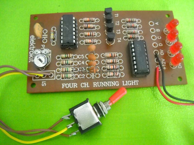
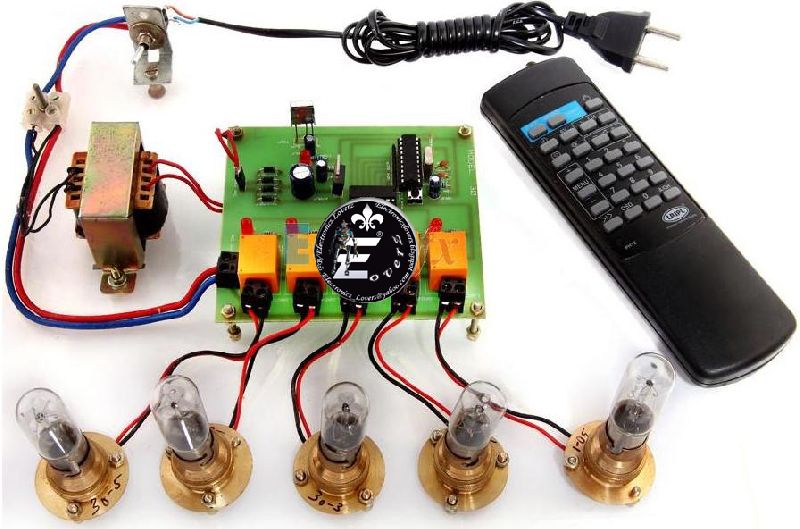
We are a noted Manufacturer and Supplier of Four Channel On/Off Control Circuit in India. This four-channel control uses only one D type latch IC1, and some associated circuitry to control four different gadgets. To control more devices, identical circuits, in multiples, can be used. IC1 consists of eight latches, out of which four are used here. The circuit incorporates the following features :
About the Circuit :
Details
The following table will help you to select the channel and corresponding on/off switch.
| Channel | On Switch | Off Switch |
|---|---|---|
| Channel-1 | S1 | S5 |
| Channel-2 | S2 | S6 |
| Channel-3 | S3 | S7 |
| Channel-4 | S4 | S8 |
| All Channels | S9 | S10 |
Power Supply : It requires +5V DC supply for circuit operation and +12V for activating the relay as shown in the circuit diagram.

We are a prominent name offering efficient Rain Alarm. Based on advanced technology, Rain Alarm alerts the people when it begins to rain. The circuit of Rain Alarm is built around monostable multi vibrator IC1. The sensor connected to trigger pin2 of IC1, is made from resistor leads or small metal foil pieces. When sensor detects rain, IC1 gets triggered and raises the alarm. In addition, when the rain stops, the circuit switches off automatically. Our esteemed customers can avail Rain Alarm at economical price.
About the Circuit :
Note on Sensor :One can make a suitable sensor according to one’s choice. A model of the sensor is shown in figure. The distance between the rails is made as small as possible so as to have a more compact and reliable sensor.

Today all of us recognize the importance of sump tanks. In many places such as hostels, apartments, hospitals or even for household purposes, we use sump water. Hence, it is very necessary to control the sump tank. We bring forth an efficient Sump Tank Controller for our customers. Sump Tank Controller is a simple and inexpensive sump tank controller, which requires only one IC1, which consists of four NAND gates. The motor turns OFF when water level in the tank goes below low level and it becomes on when water level reaches to low level and it remains on until it goes high level. The motor turns OFF again as the water goes below low level.
About the Circuit :

In many places such as hostels, apartments, school/colleges, hospitals, etc, overhead tanks are used for storing the water. As the requirement of water is large, controlling of tank is very important. Overhead Tank Controller is a specially designed circuit to overcome this problem. Overhead Tank Controller has two sensors named as HIGH and LOW immersed into the tank with reference, which is at positive potential. The motor is on until the tank is full. When it reaches to HIGH level, the motor automatically turns OFF and it remains OFF until water level goes below LOW sensor and then it becomes on again. Thus, Overhead Tank Controller prevents the overflow of water.
About the Circuit :

Our esteemed customers can avail Electronic Dice from us. A dice when thrown can take any position to give the players random number out of six. The effect can be very well experienced and even commercially exploited to play actual game of electronic dice with this kit.
In the conventional game, a dice is thrown and the player watches what position it takes out of six possible positions. The dice needs to be positioned randomly at every throw. This effect is practically implemented by a small inexpensive electronic circuit.
About the Circuit :

Earthquake/Vibration Alarm converts mechanical vibration into electrical vibration and gives alarm. The Piezo electric sensor is used to sense any kind of vibration /jerk. It produces small ac signal when activated by a jerk or vibration. Since it is very sensitive to any kind of vibration it can serve as earthquake alarm also. A piezo electrical sensor is available in market in the form of a round disc. It has two terminals for output. When we want to use it, it can be placed on the surface or can be adhered to the surface with the help of cello tape or a general purpose chemical adhesive. When the surface encounters any vibrations, these are transferred to this piezo sensor and it produces a signal.
About The Circuit : A simple circuit is built around a 555 timer IC. The output from sensor is fed to a transistor T1. Capacitor C1 and Resistor R1 act as fixed bias to the transistor T1. T1 amplifies the signal and delivers amplified output at the collector. This output is again fed to another transistor through ac coupling in order to further amplify the signal. Since T1 is weekly biased, it automatically rectifies the ac signal and only pulsating dc waveform is amplified and delivered by T2. Output of this T2 is fed to trigger input of IC555 through capacitor C3. Capacitor C3 differentiates the rising and falling edge of the signal produced at the collector of T2. The positive going pulse will not have any effect on trigger input. However negative going pulse will trigger the timer and produce HI state at its output. This HI state will glow LED D1. Also buzzer starts sounding when the sensor signal is detected. The 555 configuration is a monostable flipflop and the signal goes on retriggering this monostable. Therefore output is continuously available as long as signal is present. VR1 sets the sensitivity of the circuit and VR2 sets the timing of the monostable. If the trigger pulses which triggers the mono are generated at delayed intervals, the output may not be continuous. TO make it continuous at even the lowest frequency of signal, VR2 should be set. The circuit can be powered either from 9 v battery or from mains through eliminator.

Shadow Alarm detects moving shadow on LDR and starts a melodious sound alarm. This shadow alarm can be used as a simple burglar alarm that produces a loud beep when somebody crosses a protected area or door. The circuit is highly sensitive and can detect the shadow of the moving person from a distance of 1 meter. It does not require an aligned light beam to make the circuit standby. The beep generated from the circuit will be loud enough to detect the entry of a person in the room or the protected area being guarded. It is portable and can be places anywhere for monitoring.
About The Circuit :The circuit uses a voltage comparator and a monostable timer to give the warning alarm on detecting a moving person. IC LM741 (IC1) is used as a voltage comparator with two potential dividers in its inverting and non-inverting inputs. Resistors R2 and R3 provide half-supply voltage of near about 4.5 volts to its inverting input (pin 2). LDR1 and preset VR1, R1 form another potential divider to provide a variable voltage input to the non-inverting input (pin 3). If VR1 is properly adjusted for the required light level, the output of IC1 will be high, which drives pnp transistor T1 out of conduction. This is due to the high potential at the base of T1. The emitter voltage of T1 will be high in this condition, which inhibits IC2 from oscillation and LED1 from lighting. IC2 is wired as a monostable timer. VR2 and C1 provide a preset time delay. As a person crosses the protected area, his shadow will be sensed by LDR1 due to change in the light intensity level and the voltage at the non-inverting input of IC1 will drop momentarily. The output of IC1 suddenly becomes low, allowing T1 to conduct. This triggers the monostable (IC2) and the alarm sounds. Adjust preset VR1 until LED1 turns off at the particular light level. Keep LDR1 facing the entrance of the room or the area to be protected. Sensitivity of the circuit depends on the proper adjustment of VR1. If VR1 is correctly adjusted, the circuit can detect a moving person from a distance of about 1-3 meters.

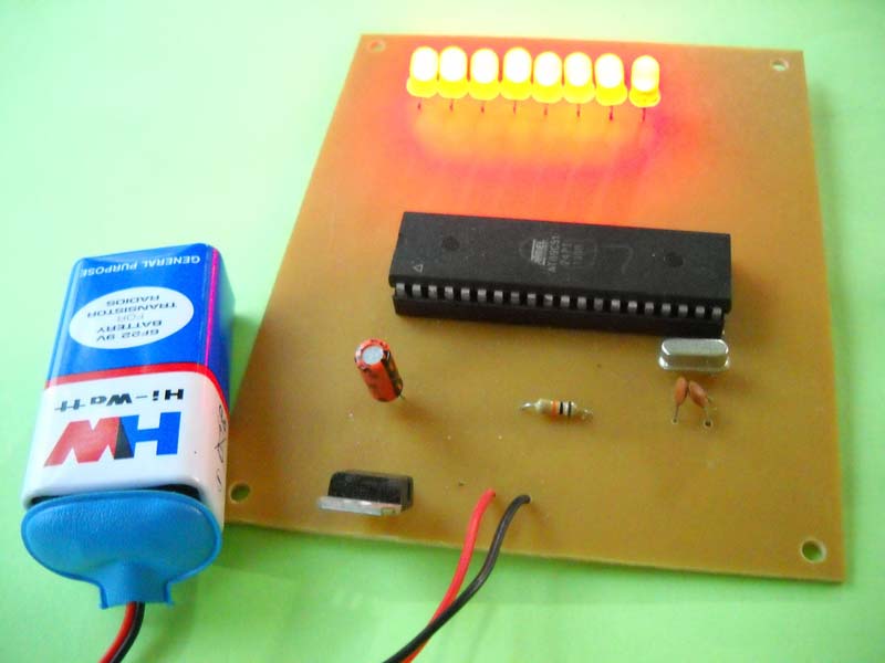
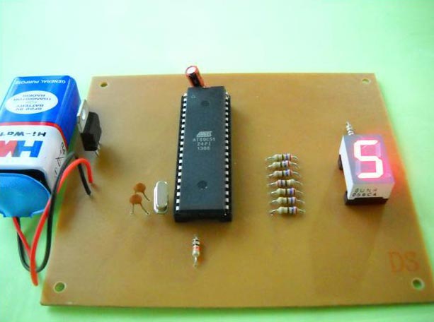
Microcontroller (89C51) Based Seven Segment Number Selector displays 0 to 9 numbers by pressing push on switches. This circuit is a simple application built around the seven segment display. The circuit has ten inputs corresponding to digits zero to nine. Whenever an input is pressed the corresponding digit is displayed on the seven segments. The microcontroller used is AT89C51 which belongs to the 8051 series of microcontroller. The circuit can be divided into two units: the controller unit and the display unit. The controller unit consists of a microcontroller circuit. The microcontroller used here is AT89C51. The display unit consists of a seven segment circuit which is interfaced to the microcontroller. The circuit is similar to the seven segment circuit with the only difference that here we have ten input pins. Each input pin corresponds to one of the digits to be displayed on the seven segments. Here the pin 0 to pin 7 of port P3, pin 6 and pin 7 of port P 1 are made the input pins. The output is sent to the seven segments through Port 2 of the microcontroller.

The circuit shown below is of an 89S51 based bi directional motor whose direction can be controlled using 2 push button switches. The circuit is very similar to the previous one except for the two push button switches. These pushbutton switches are interfaced to P0rt 3 of the microcontroller. Resistors R2 and R3 are the pull down resistors for P3.0 and 3.1 respectively. Push button controlled bi-directional DC motor the code for the above project is so written that initially when power is switched ON, the motor remains OFF. When push button switch S2 is pressed P1.0 goes high and P1.1 remains low. The motor run in the clockwise direction and this condition is maintained until S3 is pressed. When push button switch S3 is pressed the logic of P1.0 and P1.1 toggles making the motor to run in the opposite direction and this condition is maintained until the next press of S2. We are a reliable Manufacturer and Supplier of Microcontroller (89S51) Based Bi-Directional Motor With Pushbutton Controller in India.
Program :
About the program :Checking whether a particular push button is pressed is done using the CJNE (compare and jump if not equal) instruction. In simple words the CJNE instruction compares two operands and jump to a predefined LABEL if the operands are not equal. If the two operands are equal nothing happens and the next instruction is executed. Whenever push button S2 is pressed the status of P3 will be 00000001B .This status is moved to accumulator A and compared with 00000001B using the CJNE instruction. Both operands are equal means S2 is pressed and the next instruction (MOV P1, #00000001B)which makes the motor run clockwise is executed. If the operands are not equal that means the S2 is not pressed and the controller jumps to LABEL1 which is to check the S3. To check S3, status of P3 is moved to A again and it is compared with 00000010B using the CJNE instruction. Both operands are equal means the S3 is pressed and the next instruction (MOV P1, #00000010B) which makes the motor run anti clockwise is executed. Both operands are not equal means S3 is not pressed and the controller goes to check S2 again and this cycle is repeated.

Infra-Red Object Counter With Alarm can be installed at the entry gate to count the total number of people entering any venue. For example, it can be used at the railway stations or bus stands to count the people arriving per day or week. Infra-Red Object Counter With Alarm uses an infrared transmitter-receiver pair and two 7-segment displays for counter display. Infra-Red Object Counter With Alarm works even in the presence of normal light. The maximum detection range is about two meters. No focusing lens is required.
About the Circuit : The transmitter is built around IC1, which acts as an oscillator. The frequency of oscillation is determined by timing components designed around R2/R3/P1/C2.When power is on, pulse at junction of C1-R1 resets IC1 and oscillation starts. The output at pin7 given to transistor T1 which, drives IR LED denoted by D1, transmits IR radiation, which are received by IR sensor used in receiver circuit.
Receiver Circuit : The receiver circuit is designed using IR sensor, transistor T1, timer IC1, which act as a one shot multivibrator. The output of IC1 is given to transistor T2, which drives buzzer. The transmitter and receiver units are aligned such that the IR beam falls directly on the IR sensor. As long as IR beam falls on the sensor, its output remains low, T1 does not conduct and trigger pin2 of IC1 remains high. When anyone interrupts the IR beam falling on the sensor, its output goes high to drive transistor T1 into conduction and pin2 of IC2 goes low shortly. As a result, IC1 gets triggered and its pin3 goes high, transistor T2 conducts and buzzer raises an alarm. Also IC3 being a decade counter receives clock pulse at pin1. It starts counting, which is shown on 7-segment displays. At every interruption, counter increases by one. You can also reset the counter by pushing switch S1. You can count maximum 99 interruptions. After 99 interruptions, counter gets reset to ‘00’.

Auditorium Attendance Counter is very useful for counting the number of people in a hall or in a conference room. You can use it at any place. Auditorium Attendance Counter will count the difference between the number of people leaving the room and entering the room.
Auditorium Attendance Counter is based on IR interruption to detect the object. Two IR circuits are used for detecting the object moving in forward and reverse direction. Associated logic circuit makes the count up or down depending upon the direction. Two up/down counter ICs are used for counting up/down pulse. For display the count, two BCD to seven segment display driver and two common cathode displays are used. The circuit will count maximum 99 objects. Logic circuit is designed using Schmitte trigger inverter, NAND Gate, and timer circuit. The power supply section comprises mains step down transformer, full wave rectifier, 12V regulator IC and filter capacitors.
About the Circuit :
Two IR sensors detect the movement of object. It comprises two IR transmitters and associated receiver module.
The simple transmitter circuit is shown in figure. It consists of 555 Timer connected as an astable multivibrator driving an output transistor which switches the IR emitter ON and OFF. The duration of the transmitted light pulses is about 10ms and the repetition rate is just less than 1 KHz. The average current drawn by the circuit is about 12mA and the peak current through the IR diode is around 700mA.
The power supply for the transmitter is not critical provided the output voltage is not greater than 9V as this could result in the maximum current rating of IR diode.
The receiver circuit is shown in figure. An infrared photodiode is operated in the reverse bias mode. The leakage current of this diode varies with the light received from the transmitter, which causes a varying voltage to appear across the resistor of the transistor T1. The signal appearing at the collector T1 is fed to IC1, which is used as an amplifier and limiter. P1 varies the sensitivity by altering the reverse bias voltage of the diode D1.
When light pulses are being received from the transmitter a negative going pulse train with amplitude in excess of 1V peak to peak appears at the output of IC1 (pin8). This turns T2 ON and OFF continuously, charging up C11. T3 is thus always turned on T4 is turned OFF.
When the light beam between the transmitter and receiver is interrupted, the amplitude of the pulse train from the output of IC1 will fall. T2 will be cut OFF, C11 will discharge, T3 will turn OFF, and T4 will turn ON. This energizes the relay. Once the light beam is restored the relay will of course, drop out again but can be made to hold in for several seconds after the light beam has been restored by adding the components shown dotted. R12 and C12 are designed according to holding time. Alternatively latching arrangement may be used that will hold the relay on a reset button is pressed.
Initially consider the object is moving from A to B. When first IR beam is interrupted, transistor T4 is turned ON and logic ‘0’ is fed to pin1 of IC1(A), which is a Schmitte trigger inverter. The high output at pin2 of IC1(A) is given to the inputs of NAND Gate IC2(A). The output of NAND Gate is zero and this output is given to trigger pin2 of timer IC3. The output of NAND gate acts as a trigger input to timer. The output of timer remains high depending on the setting time, which varies from 1sec to 100sec. The requirement is that the timer output remains high until second IR beam is interrupted. This timer output acts as one of the input of NAND gate IC2(C). When the second IR beam is interrupted, second IR receiver is triggered. The output transistor turns on shortly and a short low pulse acts as another input of NAND Gate IC2(C). Thus, output of this NAND Gate IC2(C) becomes shortly low and acts as a UP pulse to counter IC6 (40192). Thus, counter is incremented and the count is displayed on seven-segment display. The output of 40192 is in BCD format. For converting BCD input to seven-segment code BCD to seven-segment decoder IC 4055 is used, which drives seven-segment display. Here maximum count is 99, which can be increased by cascading more counter and display stages.
When object is moving from B to A, the same operation is repeated as above. The low pulse at output of NAND Gate IC2 (D), acts as a down pulse to counter IC. Thus, the counter is decrement by one. The resultant count is displayed on two seven-segment displays.
Installation :Install the two IR transmitter detector pairs and connect them to the respective logic circuit. The first IR pair comprises IR LED1 and PHOTODIODE1. The second pair comprises IR LED2 and PHOTODIODE2. Orient the two IR LED transmitters such that their IR beams fall on the respective detector. Also, ensure that the IR beam off one pair doesn’t affect the other pair’s IR beam.
Counter will count will only when somebody interrupts IR rays of the first pair and then second pair sequentially. It will count down when second IR rays interrupted first and then first IR beam.

Committed to quality, we have established ourselves as a Manufacturer and Supplier of AVRoN16. AVRoN16 is a low cost, versatile ATMEGA16 based development board for beginners and researchers, best suited for the AVR Based Robotics and Embedded Project. Precision designs and efficient performance are the prominent attributes of our AVRoN16.
Detail
Package Content :

CoRePro Breakout Board is a full-featured development board for the NXP's P89V51RD2 microcontroller, which is most popular in industry. CoRePro is cost effective 40 pin, features rich microcontroller that offer real value to developer in terms of capabilities and features. CoRePro has 64KB of flash memory and 1024 bytes on chip SRAM. CoRePro is an ideal platform to build and execute numerous projects on P89V51RD2 microcontroller. All the pins of the controller are user accessible for performing their own customize project.
Detail :
Package Content :

Ultrasonic Range finder: HC-SR04 provides 2cm-4meter non-contact measurement function, the ranging accuracy can reach to 3mm. The modules include ultrasonic transmitters, receiver and control circuit. Typical application of Ultrasonic Range finder: HC-SR04 is measurement of distance.