Our Products
Our offered Product range includes Treadle Guillotine Shearing Machine, Portable Shearing Machine, Hand Operated Shearing Machine, Plywood Hot Press Machine and Hand Press Machine.

Treadle guillotine shearing machines are indispensable in sheet metal industries as they lead amongst all on account of versatile design, rigid construction, rigorous tests for the capacities and appearance. They are specially designed for rapid and continuous cutting of steel sheets of varied widths and trimming them in unlimited lengths. Available in cast iron body or in all steel construction.
Features :
Tradle guillotine shearing machines are designed to cut sheets of ferrous and non-ferrous metals of the following capacities.
| Inches | S.W.G. | |
| Mild steel, 26 tons tensile | 0.048 | 18 |
| Stainless steel annealed, 50 tons tensile | 0.022 | 24 |
| Brass, hard, 36 tons tensile | 0.032 | 21 |
| Brass, half hard, 30 tons tensile | 0.040 | 19 |
| Copper, hard 20 tons tensile | 0.064 | 16 |
| Copper, soft annealed 16 tons tensile | 0.072 | 15 |
| Aluminium, half hard, 16 tons tensile | 0.072 | 15 |
| Aluminium, copper alloy 40 tons tensile | 0.028 | 22 |
| Duraluminium, 28 tons tensile | 0.040 | 19 |
| Model No. | AMI-6 | AMI-12 | AMI-18 | AMI-24 | AMI-36 | AMM-40 | AMI-48 |
| Y- Maximum width of cut | 6" | 12" | 18" | 24" | 36" | 39" | 48" |
| Capacity in mild steel S.W.G. | 24 | 24 | 20 | 20 | 20 | 20 | 20 |
| Blade size | 7" | 13" | 19" | 25" | 37" | 40" | 50" |
| Treadle design | Single pad | Single pad | Open pad | Open pad |
Open pad |
Open pad |
Open pad |
| No. of tension springs provided | 1 | 2 | 2 | 2 | 2 | 2 | 3 |

The portable electric shear model 'AMI-3' is very useful and an indispensable tool in all workshops, assembly line, erection sites, coach building shops, tin smith and alike industries as it is handy, convenient and easily accessible to different types of shearing jobs in various materials upto 3 mm thickness (in M.S. with tensil strength 45kg sqr. mm.) for straight, round, ovel, curved andor irregular shapes at rapid speed reducing thereby the production and maintanance cost considerably. A moving cutter moves against a stationary one in the anvil. The cutting speed is high and there is no loss of material. While a shear can be used for splitting sheets where the resistance to bending is not great, they are not recommended for cutting across wide and thick plates. On heavier gauges of material they should be regarded as trimming shears, main portion remaining flat; while the cut portion is bent away beneath the anvil. The anvil is designed so that scribed lines are well in view and are easily followed allowing straight lines and curves to be easily cut. The minimum cutting radius is approximately 3.12lnch. Blades are of special die steel and are of simple design. They are of sufficient length to stand fro 10 to 15 grindings. The motor is for intermitent operation and is of fan cooled type, suitable for operation on AC. 220 volts, single phase, 50 cycles with built-in "ON" "OFF" Switch, 2 meter long cable and plug.

hand lever shearing machines fitted with blades and handle, suitable for cutting sheets in unlimited length, rounds, flates, etc.
.


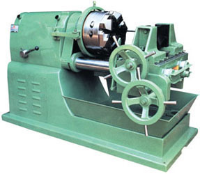
Pipe Threading Machines are designed to give maximum efficiency and reliable performance under the most severe conditions of service with minimum maintenance cost. All the necessary requirements are combined in this model to form the basic fundamentals of correct threadings. All the gears are made of case hardened steel with extra large face width and tooth thickness and cut on hobbing machine for noiseless operation even at high speeds. Naturally they are built with high standards of workmanship, material and quality.

Pipe Threading Machines are designed to give maximum efficiency and reliable performance under the most severe conditions of service with minimum maintenance cost. All the necessary requirements are combined in this model to form the basic fundamentals of correct threadings. All the gears are made of case hardened steel with extra large face width and tooth thickness and cut on hobbing machine for noiseless operation even at high speeds. Naturally they are built with high standards of workmanship, material and quality. The Headstock is of top quality casting proving support to the spindle bearings. The spindle swing or taper roller bearings are of best steel with a grounded finish to give accurate results. Gears of Head Stock are running in Oil Bath with Oil level window.


| TECHNICAL FEATURES : | |
|
|
STANDARD ACCESSORIES :
EXTRA ACCESSORIES :
| Model | AMI - 12 | AMI - 18 | AMI - 24 | AMI - 30 | AMI - 36 | AMI - 42 |
| A - CAPACITY | 12" | 18" | 24" | 30" | 36" | 42" |
| Length of Ram Stroke | 305 mm | 457 mm | 610 mm | 762 mm | 915 mm | 1070 mm |
| Length of Ram | 711 | 991 | 1232 | 1474 | 1651 | 2108 |
| Length of Width of Ram bearing | 724 x 203 | 686 x 273 | 867 x 30 | 975 x 325 | 1130 x 300 | 1600 x 330 |
| Max. & Min. distance from Table of Ram | 257 x 41 | 381 x 83 | 508 x 76 | 610 x 102 | 525 x 102 | 530 x 102 |
| B- TABLE | ||||||
| Working Surface of Table | 305 x 228 | 457 x 305 | 610 x 356 | 762 x 406 | 915 x 457 | 196 x 533 |
| Max. Table Travel Horizontal | 330 | 483 | 635 | 787 | 860 | 1050 |
| Max. Table Travel Vertical | 140 | 305 | 406 | 483 | 525 | 455 |
| Angular Movement of Table on either sides | 60 L 60 R | 60 L 60 R | 60 L 60 R | 60 L 60 R | 60 L 60 R | 60 L 60 R |
| C - TOOL HEAD | ||||||
| (Max. Vertical Traval of Tool Slide) | 140 | 152 | 204 | 203 | 225 | 300 |
| Maximum Swivel of Tool Head | 60 L 60 R | 60 L 60 R | 60 L 60 R | 60 L 60 R | 60 L 60 R | 60 L 60 R |
| D - BASE | ||||||
| Length of Width of Base | 940 x 483 | 1346 x 502 | 1676 x 610 | 1829 x 660 | 1980 x 660 | 2286 x 762 |
| E - SPEEDS & FEEDS | ||||||
| Dia of Clutch Pulley | 235 | 311 | 311 | 311 | 380 | 380 |
| Range of Ram Speeds | 3 | 4 | 4 | 4 | 4 | 4 |
| Stroke per minute | 30, 60, 90 | 16, 32, 64, 96 | 12, 24, 48,72 | 8,16, 32, 48 | 10, 20, 30, 50 | 8, 16, 32, 48 |
| Dia of Motor Pulley | 51 | 70 | 70 | 76 | 88 | 88 |
| Range of Table Feed per Stroke of Ram | 0.299 | 0.220 | 0.229 | 0.229 | 0-22 to 0-88 | 150 to 600 |
| Range of Tool Head Feed | Hand Feed | Hand Feed | Hand Feed | Hand Feed | Hand Feed | Hand Feed |
| Automatic Tool Head Feed & Tool Lifting | On Order | On Order | On Order | On Order | On Order | On Order |
| F- DRIVE ELECTRICAL EQUIPMENTS | ||||||
| Power Supply | 1 HP (75kw) | 2 HP (1.5kw) | 15 HP (12.2kw) | 5 HP (3.75kw) | 7.5 HP (5kw) | 10 HP (7.5kw) |
| Speed RPM | 1440 RPM | 1440 RPM | 1440 RPM | 960 RPM | 960 RPM | 960 RPM |
| V. Belt Section | B-55 | B-55 | B-55 | B-58 | B-70 | B-75 |
| Main Switch Starter (Push Button Type) | 3.5 AMP | 3.5 AMP | 5 AMP | 5 AMP | 5 AMP | 3.5 AMP |
| G - OVERALL DIMENSIONS & WEIGHT | ||||||
| Length | 1219 | 1580 | 1981 | 2150 | 2500 | 2875 |
| Width | 762 | 948 | 1092 | 1219 | 1350 | 1500 |
| Height | 1371 | 1400 | 1600 | 1550 | 1700 | 1850 |
| Weight (Approx) | 700 Kgs | 1500 Kgs | 2000Kgs | 2700Kgs | 3500 Kgs | 4000 Kgs |

Treadle guillotine shearing machines are indispensable in sheet metal industries as they lead amongst all on account of versatile design, rigid construction, rigorous tests for the capacities and appearance. They are specially designed for rapid and continuous cutting of steel sheets of varied widths and trimming them in unlimited lengths. Available in iron body or in all steel construction. FeaturesHigh tesile spings for quick return of treadle.4 Cutting edged hardened and ground quality blades.Rigid and Streamlined construction .Spring loaded sheet holding device.
In every machine, the bed and top beam have full adjustments for correct settirig and easy removal of blades for accurate cuttirig and for regrinding. The spring loaded pressure pad holds the sheets firmly while shearing thereby giving the perfect parallelism of cutting on either side. The adjustable front and back gauges with running Tee slots facilitate adjustment of various widths of the cuts and avoid any kind of twistings, turning of sheets while cutting. Square guide on the side of the table facilitates square cuts. The cutting edge blades avoid frequent grinding and adjustment and also very easy to grind to the rectangular shape and are manufactured in collaboration with very good German firm. Highly compared English springs balance the treadle to correct level. The top beam guides are adjustable for compensating wear and tear as also setting of the upper blade. These blades can be used with slight change in cutting angle to ribs, plastics, card board, rubber, mica etc., without any sign of squeezing or crushing.
| Model | AMI-6 | AMI-12 | AMI-18 | AMI-24 | AMI-36 | AMI-40 | AMI-48 |
| Y-Maximum width of cut | 6" | 12" | 18" | 24" | 36" | 39" | 48" |
| Capacity in mild steel S.W.G. | 24 | 24 | 20 | 20 | 20 | 20 | 20 |
| Blade size | 7" | 13" | 19" | 25" | 37" | 40" | 50" |
| Treadle design | Single Pad | Single Pad | Open Pad |
Open Pad |
Open Pad |
Open Pad |
Open Pad |
| No. of tension springs provided | 1 | 2 | 2 | 2 | 2 | 2 | 3 |

Universal Ironworker so far as the shearing, punching, notching / coping and cropping of flats, plates, squares, rounds and structural sections of any shape are concerned. The coping head is of vary study design and construction and can be easily and quickly turned into a notcher or alternatively into a punching head. Agin it can be fitted with special tool holder and tools for notching T section in both flanges simultaneously. Back stops and gauges can be supplied for production job at extra cost and they will in no way interfere with the shearing of plates or other operations. The standard machine is equipped with clutch : Mechanical hand lever operatedGears : Made of steelMotor : AC, 440/3/50 totally enclosed fan cooled with V belts, pulley, Starter and sturdy guards.Blades : To cut sheets, flats, angles, T, Round, Square bar cutting, V notching or punching attachment (specify while ordering)
OPTIONAL ATTACHMENTS :
| Modol No. | AMI-1 | AMI-2 | |
| M.S. Plate upto | mm | 8 | 10 |
| Flat Bar upto | mm | 75 x 12 | 100 x 12 |
| Length of Blade | mm | 175 x 175 | |
| CROPPING | |||
| Round Bars | mm | 25 | 30 |
| Square Bars | mm | 22 | 25 |
| Angles at 90° | mm | 63 x 6 | 75 x 6 |
| T Section | mm | 50 x 6 | 60 x 6 |
| PUNCHING | |||
| Dia x Thickness | mm | 18 x 9 | 20 x 10 |
| NOTCHING | |||
| With Triangular Blade angle or square | mm | 38 x 6 | 38 x 6 |

The thread rolling is basically a cold-forging process that forms the entire length of an external thread by displacing the bla^E. material. Threads are produced on the blanks of predetermined diameter by a rolling action under pressure and between two rotating cylindrical steel roll dies whose working faces are suitably threaded. This action plastically deforms the blank in such a manner that a portion of the blank metal is displaced to form the root of the thread and raised in unbroken fibw-flow lines to form the crest of the thread. The roll dies rotate synchronously on parallel or slightly tilted horizontal spindle shafts that are adjustable by sliding laterally. The dies are made of special steel alloy with an exceptional hardness and toughness resulting in maximum wear resistance. The blank is placed on a carbide tipped work rest blade or center support disposed between the dies and after a complete cycle v of approach, rolling and release of the hydraulically operated right hand spindle shaft the rolled thread is removed. The blank is placed in the rolling position, either by hand or automatically. A timer built into the machine release the hydraulic pressure on the roll dies when the required diameter is completed and returns the right hand spindle head to its starting position.

APPLICATIONS : This machine is best suited for small batch production or when cost of press tools and dies is prohibitive. It enhances quality and productivity by doing such jobs which used to be done by skilled men and hand tools. The machine has eliminated expensive trimming dies in many modern workshops. Fabricators, Control panel manufacturers, cabinet & vehicle body makers, fan & impeller industry in addition to many others find it a most valuable asset. While the capacities indicated below are for mild steel, the machine is often used for many other materials as well.
DESCRIPTION : The Sheet Metal Nibbling Machine is a rugged, sturdy and reliable multipurpose machine capable of sheet cutting & forming operations. Its verstility is best expressed by terming it the Sheet Metal Workers lathe. The working principle on which nibbling operates is the sheet is cut or formed between the fast reciprocating motion of an upper tool (powered by an electric motor and driven by an ecentric crank) and a stationery lower tool, by progressive punching, as the sheet is fed.
OPERATIONS :
Accessories : Complete electricals, a set of straight cutting tools with the holders, necessary keys, spanners for the operation of machine, feeler gauge & operation manual form the std. accessories supplied with the machine. Various attachments for straight sheet feeding, circle guiding, louvre cutting, rotary nibbling copy & coordinate table with scales & ball tops antivibration pads etc. are available.
Tools : Straight, figure and circle cutting tools, Flanging tools, beading tools, flouring tools etc. are available at extra cost.
STANDARD ACCESSORIES :
OPTIONAL ACCESSORIES :
| MODEL | PN-3 | PN-5 | PN-8 | ||
| CAPACITIES | M. Steel 45 kg. / mmz | M. Steel 45 kg. / mm2 | M. Steel 45 kg./mm2 | ||
| From the edge | mm | 3.2 | 5 | 8 | |
| STRAIGHT CUTTING | Inside With starting hole | mm | 3.2 | 5 | 8 |
| Sheet Without starting hole | mm | 2.5 | 4 | 6 | |
| FIGURE CUTTING | Sheet thickness | mm | 1.5 | 2 | 2.5 |
| LOUVER CUTTING | Sheet thickness | mm | 2.25 | 3 | 4 |
| From the edge | mm | 2.5 | 4 | 6 | |
| NIBBLING | Inside With starting hole | mm | 2.5 | 4 | 6 |
| Sheet Without starting hole | mm | 2 | 3 | 4 | |
| SLOT CUTTING | Sheet thickness/width of slot | mm | 2.5/8 | 4/10 | 5/10 |
| RECT CUTTING | Sheet thickness/width of notch | mm | 2/8 | 3/10 | 4/12 |
| FOLDING | Sheet thickness/depth of fold | mm | 2/6 | 2.5/8 | 3/10 |
| BEADING | Sheet thickness/depth of bead | mm | 2/4 | 2.5/5 | 3/6 |
| FLANGING | Sheet thickness/height of flange | mm | 2/8 | 3/12 | 3/15 |
| DISHING | Sheet thickness | mm | 2 | 2.5 | 3 |
| MACHINE SPECIFICATIONS | |||||
| Throat depth | mm | 900 | 1000 | 1250 | |
| Minimum circle dia. cut from square blanks | mm | 740 | 830 | 1000 | |
| Net weight approximate | Kgs. | 700 | 1600 | 2200 | |
| Length of stroke | mm | 1 to 8 | 1.5 to 9 | 2 to 10 | |
| No. of strokes per minute | No. | 1440 | 1440 | 720/1440 | |
| Maximum tool lift | mm | 15 | 15 | 25 | |
| Motor 3 Phase | H.P. | 2 | 3 | 5 | |