Our Products
Our offered Product range includes Shimoga Model Heavy Duty Lathe, Tap Grinder, CNC Cutting Machine, Wire Straightening and Planner Bed Change Gear Heavy Duty Lathe Model Roll Master.


Conrete Mixers, SMM - 1 (107) Concrete Mixer With Mechanical Hopper, Our product portfolio now includes over 300 cutting-edge products that meet various requirements & specifications. Atlas Machines also has presence in the global markets, and exports Machinery & Equipment World Wide.


STANDARD ACCESSORIES :
| Model | AMI - 1 | AMI -2 | AMI -3 | AMI-4 | AMI-5 | AMI-6 | AMI-7 | AMI-8 |
| Length of bed | 4.1/2' | 6' | 6'6" | 8'6" | 6'6" | 8'6" | 10' | 12' |
| Width of bed | 12" | 12" | 14" | 14" | 17" | 17" | 17" | 17" |
| Height of centre | 10" | 10" | 12.1/2" | 12.1/2" | 16" | 16" | 16" | 16" |
| Swing over bed | 20" | 20" | 25" | 25" | 30" | 30" | 30" | 30" |
| Swing in gap | 30" | 30" | 34" | 36" | 46" | 46" | 46" | 46" |
| Swing over saddle | 13" | 13" | 15" | 17" | 22" | 22" | 22" | 22" |
| Width of gap in front of face plate | 10" | 10" | 12" | 12" | 12" | 12.1/2" | 12.1/2" | 12.1/2" |
| Admit between centre | 26" | 36" | 36" | 60" | 36" | 40" | 60" | 84" |
| Spindle Bore | 2.1/8" | 2.1/8" | 2.3/8" | 2.3/8" | 3.1/8" | 3.1/8" | 3.1/8" | 3.1/8" |
| Spindle speed | 6 | 6 | 6 | 6 | 6 | 6 | 6 | 6 |
| Size of morse taper No. | 4 | 4 | 4 | 4 | 4 | 4 | 4 | 4 |
| Lead screw pitch | 2 | 2 | 2 | 2 | 2 | 2 | 2 | 2 |
| Power required HP | 2 | 2 | 3 | 3 | 3 | 3 | 5 | 5 |
| Dog chuck size | 12" | 12" | 14" | 16" | 20" | 20" | 20" | 20" |

standard equipment :
extra equipment :
| AMI-60GN | AMI - 50 GN | AMI - 40 GN | AMI-25 G | AMI - 25 S | |
| Spindle Hollow | 62 | 52 | 42 | 32 | 28 |
| Maximum Collet Capacity | 60 | 50 | 40 | 25 | 25 |
| Range of Spindle Speeds | 90 - 1000 | 100-1050 | 100-1050 | 275-900 | 650-1660 |
| Effective Strokes of Turret Slide | 180 | 175 | 165 | 130 | 110 |
| Bore Size in Turret Hex Head | 32 | 32 | 32 | 25 | 25 |
| Center of Holes above Turret Slide | 55 | 55 | 55 | 55 | 55 |
| Max. distance between spindlenose to turret face | 430 | 430 | 430 | 400 | 375 |
| Cross Slide Transverse Travel | 150 | 150 | 150 | 95 | 95 |
| Cross Slide Longitudinal Travel | 300 | 300 | 300 | 300 | 300 |
| Length of Bed | 1375 | 1375 | 1375 | 1275 | 1050 |
| Width of Bed | 230 | 230 | 230 | 178 | 178 |
| Height of Center above Bed | 190 | 190 | 190 | 165 | 165 |
| Floor Space required | 3m x 1m | 3m x 1m | 3m x 1m | 3m x 1m | 2.5m x 1m |
| Net Weight of Machine | 1850 | 1850 | 1850 | 850 | 650 |
| Packing Size (Approx.) in fts | 5 x 3 x 5 | 5 x 3 x 5 | 5 x 3 x 5 | 4.5 x 3 x 5 | 4 x 3 x 5 |
| MODEL | AMI-42G-TT | AMI-32G-TT |
| Spindle Hollow | 50 mm | 38 mm |
| Maximum Collet Capacity | 42 mm | 32 mm |
| Range of Spindle Speed | ||
| Slow Group (RPM) | 60-95-150-240 | 240-152-380 |
| Fast Group (RPM) | 380-600-950-1500 | 950-600-1500 |
| Turret Feed Rates | .05-.1-.2 mm/rpm | 40-82-160 RPM |
| Effective Strokes of Capstan Slide | 150 mm | 130 mm |
| Bore Size in Hexagonal Turret | 25 mm | 25 mm |
| Centre of Holes above Turret Slide | 54 mm | 45 mm |
| Maximum Distance between Spindle Nose to Turret Face |
400 mm |
360 mm |
| Cross Slide Traverse Travel | 140 mm | 140 mm |
| Cross Slide Longitudinal Travel | 230 mm | 200 mm |
| Length of Bed | 1330 mm | 1200 mm |
| Width of Bed | 190 mm | 180 mm |
| Height of Centre above Bed | 170 mm | 160 mm |
| Floor Space Required | 800 mm x 1600 mm | 750 mm x 1400 mm |
| Net Weight of Machine | 1500 Kgs. | 1100 Kgs. |
| Gross Weight of Machine | — | 1250 Kgs. |
| Packing Case Size | 1800 x 900 x 1425 mm | 800 x 1500 x 1400 mm |
| MODEL | AMI S - 32 | AMI S - 38 |
| Collet capacity | 32(1.1/4") | 38(1.1/2") |
| Hole through spindle | 32 | 38 |
| Height of centres | 135 | 135 |
| Maximum turning dia over Truco slide | 120 | 120 |
| Transversal stroke of Truco cutting of slide | 173 | 173 |
| Useful stroke of turret carriage | 125 | 125 |
| Number of spindle speed | 6 | 6 |
| Spindle speed | 300 to 1400 RPM | |
| Spindle speed (with gear box) | 50 to 3000 RPM | |
| Bore of hexagonal turret (Norm CM) | 25.4 | 25.4 |
| Average distance between spindle & turret carriage | 220 | 220 |
| Width of bed | 150 | 150 |
| Cross section of tool to use | 10 | 10 |
| Average Horse-Power of motor | 2 H.P. double speed | |
| Floor space required without bar-feed device | 42" x 24" | 42" X 24" |
| No. of feeds | 3 | 3 |
| Net weight approximate (Kgs) | 600 | 650 |
| Gross weight approximate (Kgs) | 800 | 850 |

standard accessories : two dead centres, centre sleeves, square tool post, tool post key, gear set for mm & inch thread, carrier plate, motor pulley, thread chart, suitable electric motor, dog chuck with flangue, r/f switch, v belt. optional accessories :quick change norton gear box, rear tool post, taper turning attachment, coolant unit with assembly, machine lamp, 3 jaw true chuck, chuck flange, face plate, steady rest & follow rest, revolving centre.
.
| Model | Upper Side Counter | |
| Size | 3'.6" / 4'.6" | |
| Inch. | mm | |
| Length of Bed | 42/54" | 1050/1370 |
| Width of Bed | 9-3/8" | 238 |
| Height of Centre | 6-1/2" / 8" | 165/200 |
| Admit between Centres | 15"/27" | 354/675 |
| Dia. of Hole through Spindle | 1-5/8" / 2" | 41/50 |
| Swing over Bed (Max.) | 13"/14" | 355/400 |
| Swing in Gap (Max.) | 20"/24" | 508/508 |
| Swing over cross slide | 8"/10" | 203/203 |
| Tail Stock Spindle Travel | 5" | 127 |
| Spindle Speeds No. | 8 | |
| Range | 25-796 RPM | |
| Spindle Morse Taper | MT-4 | |
| Lead Screw Dia. | 1" x 4 T. P. I. | |
| Threading Range | 0.5 to 40 T. P. I. & 0.5 to 8 mm pitch | |
| or | ||
| Dia Threading Range | 1" x 6T. P. I. 1 to 45 T. P. I. & 0.5 to 6 mm pitch | |
| Required H.P. | 1 H.P. | |

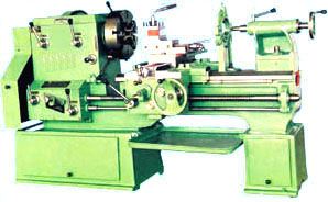
DESIGN & WORKMANSHIP : AMI lathe machines have been designed to cater need of sustained accuracy and superb finishing. AMI lathes are guaranteed for their original design, and are tested to the graded limits with specially imported precision tools. BED : The bed being the foundation of the lathes is carefully designed and is of high grade cast iron. It has cross-ribs to support its walls and three inverted 'VEES' assembled with a removable gap for large swing. HEAD STOCK : The head-stock is of top quality castings providing support to the spindle bearings. The bearings are of the following three types: (a) Parallel Brass with thrust Bearing, (b) Conical Brass, (c) Taper Roller Bearing. The inain spindle is the best steel with a finish to give accurate results. Head Stock gears are of "Clutch system" of high production in small machines & "Kirloskar system" in large machines. SADDLE : The 'V ways running on the bed and the slides are most accurately hand scrapped and aligned accurately with the bed and the headstock. The saddle is fitted with 'Hand' and 'Automatic' transfers along the bed with steel rack and Pinion.It is assembled with cross and upper slide graduated to give desired angles. TOOL POST : The Toll-Post is made out of one piece steel block and can hold four different tolls at a time and can be swivelled to any desired angle. APRON : The apron gives movement to the saddle for screw cutting sliding and surfacing by means of enclosed gears and half nut. All gears are of steel and are well tempered. TAIL STOCK : The tailstock is designed to give maximum strength bolt operation. It has long bearing within the barrel and ensures true alignment. THREE SPEED GEAR BOX : The Three speed gear box is provided with the lathe to obtain coarse, medium and fine cutting ranges, both long and cross on the feed bar through gears. The lead screw with accurate threads is to be used only for thread cutting & can be engaged or disengaged with a handle provided on the gear box while the other handle is for obtaining the desired three speeds.
STANDARD ACCESSORIES :
|
|
| EXTRA ACCESSORIES : |
| Bed Standard Length | 10' | 13 1/4' |
16' | 18' | 20' | 10 1/2' |
12' | 16' | 18' | 20' | 14' | 16' | 18' | 20' | 22' | 16' | 20' | 22' | 24' | 26' | 28' | 30' |
| Height of Centre | 161/2" | 161/2" | 161/2" | 161/2" | 161/2" | 24" | 24" | 24" | 24" | 24" | 18" | 18" | 18" | 18" | 18" | 36" | 36" | 36" | 36" | 36" | 36" | 36" |
| Width of Bed | 20" | 20" | 20" | 20" | 20" | 30" | 30" | 30" | 30" | 30" | 24" | 24" | 24" | 24" | 24" | 42" | 42" | 42" | 42" | 42" | 42" | 42" |
| Swing over Saddle | 24" | 24" | 24" | 24" | 24" | 38" | 38" | 38" | 38" | 38" | 25" | 25" | 25" | 25" | 25" | 60" | 60" | 60" | 60" | 60" | 60" | 60' |
| Swing in Gap | 52" | 52" | 52" | 52" | 52" | 74" | 74" | 74" | 74" | 74" | 50" | 50" | 50" | 50" | 50" | 106" | 106" | 106" | 106" | 106" | 106" | 106" |
| Swing over Bed | 32" | 32" | 32" | 32" | 32" | 47" | 47" | 47M | 47" | 47" | 35" | 35" | 35" | 35" | 35" | 71" | 71" | 71" | 71" | 71" | 71" | 71" |
| Width of Gap in front of Face Plate | 11" | 11" | 11" | 11" | 11" | 20" | 20" | 20" | 20" | 20" | 12" | 12" | 12" | 12" | 12" | 20" | 20" | 20" | 20" | 20" | 20" | 20" |
| Admit Between Centres | 60" | 100" | 130" | 154" | 178" | 48" | 72" | 120" | 144" | 168" | 100" | 124" | 148" | 172™ | 196" | 107" | 155" | 179" | 203" | 227" | 251" | 275" |
| Spindle Bore | 4 1/4" |
4 1/4" |
4 1/4" |
4 1/4" |
4 1/4" |
4 3 /4" |
4 3 /4" |
4 3 /4" |
4 3 /4" |
4 3 /4" |
4 1/4" |
4 1/4" |
4 1/4" |
4 1/4" |
4 1/4" |
5" | 5" | 5" | 5" | 5" | 5" | 5" |
| Spindle Speed | 8 | 8 | 8 | 8 | 8 | 8 | 8 | 8 | 8 | 8 | 8 | 8 | 8 | 8 | 8 | 8 | 8 | 8 | 8 | 8 | 8 | 8 |
| Size of Morse Taper | 3MT | 3MT | 3MT | 3MT | 3MT | 4MT | 4MT | 4MT | 4MT | 4MT | 4MT | 4MT | 4MT | 4MT | 4MT | 5MT | 5MT | 5MT | 5MT | 5MT | 5MT | 5MT |
| Pitch of Change Wheel | 7DP | 7DP | 7DP | 7DP | 7DP | 6DP | 6DP | 60P | 60P | 6DP | 7DP | 7DP | 7DP | 7DP | 7DP | 6DP | 6DP | 6DP | 6DP | 6DP | 6DP | 6DP |
| Cone Width of Belt | 3 1/2" |
3 1/2" |
3 1/2" |
3 1/2" |
3 1/2" |
4" | 4" | 4" | 4" | 4" | 3 1/2" |
3 1/2" |
3 1/2" |
3 1/2" |
3 1/2" |
4" | 4" | 4" | 4" | 4" | 4" | 4" |
| Speed of Countershaft | 100 | 100 | 100 | 100 | 100 | 80 | 80 | 80 | 80 | 80 | 80 | 80 | 80 | 80 | 80 | 80 | 80 | 80 | 80 | 80 | 80 | 80 |
| Dia of Lead Screw | 2 1/4" |
2 1/4" |
2 1/4" |
2 1/4" |
2 1/2" |
2 1/2" |
2 1/2" |
2 1/2" |
2 1/2" |
2 1/4" |
2 1/4" |
2 1/4" |
2 1/4" |
2 1/4" |
2 1/4" |
2 3 /4" |
2 3 /4" |
2 3 /4" |
2 3 /4" |
2 3 /4" |
2 3 /4" |
2 3 /4" |
| Lead Screw Pitch (TPI) | 2 | 2 | 2 | 2 | 2 | 2 | 2 | 2 | 2 | 2 | 2 | 2 | 2 | 2 | 2 | 2 | 2 | 2 | 2 | 2 | 2 | 2 |
| Power Required (HP) | 3 | 7.5 | 7.5 | 7.5 | 7.5 | 10 | 10 | 10 | 10 | 10 | 7.5 | 7.5 | 7.5 | 10 | 10 | 15 | 20 | 20 | 20 | 25 | 25 | 30 |

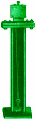
The performance of a Diesel Engine depends upon its injection pump. Diesel fuel pump test benches records and sets the performance of the fuel injection pump to the maximum accuracy.

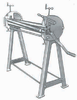
Automatic wire straightening and cutting machine having an exclusive and elite combination of speed and accuracy backed by intensive research of experts. These machines are used where wire is further processed in rods, coiled wire accurate straightening, close length tolerances and high output are of importance, widely used by electric welding rods manufactures, electric fan guards, refrigerator racks, cloth hangers, automobile parts, electric parts industry, gives you both financial and inner core satisfaction as it is very easy to use requires no special skill. Indefinite length of wire can be cut out without automatic attachment. The machine operates by drawing the wire from the coil through the fast rotating spinner, passes through a cutting of tool into the scaling bar where it strikes at the adjusted length and this stroke makes the cutting mechanism complete. This straightening function is performed by 5 straightening blocks which are adjustable and contains a simple to use straightening bush lets the user to make replacement to his own work
| Type | AMI - 40 |
AMI - 25 |
AMI - 20 |
AMI - 16 | AMI - 15 | AMI - 13 | AMI - 10 | AMI - 8 | AMI-7 | AMI-5 |
| Thickness of Wire | mm 15-40 .590-1.500 |
mm 10-25 .375-1" |
mm 7.7-20 0.320-0.787 | mm 7.7-16.2 0.320-0.625 | mm 8-15 0.315-0.590 | mm 3.2-12.7 0.125-0.5 | mm 3.2-10 0.125-0.375 | mm 3.2-8 0.125-0.315 | mm 2-7 0.80 - 0.250 B.W.G. 14.3 | mm 1.6-5 .062 - 0.192 B.W.G. 16.6 |
| Length of Wire to be cut | mm 300-3600 | mm 300-3600 | mm 75-1800 | mm 75-1800 | mm 75-1800 | mm 50-1200 | mm 25-1000 | mm 25-1000 | mm 25-1000 | mm 26-300 |
| Automatically | 12" - 144" | 12" - 144" | 3" - 72" | 3" - 72" | 3" - 72" | 2" - 48" | 1" - 36" | 1" - 36" | 1" - 36" | 1" - 12" |
| Capacity per Min. | Ft. 30 | Ft. 35 | Ft. 40 | Ft. 40 | Ft. 40 | Ft. 45 | Ft. 50 | Ft. 55 | Ft. 60 | Ft. 70 |
| Power of Motor | HP 35,10 & 5 | HP 20, 5 & 5 | HP 15 & 3 | HP15&3 | HP10 & 3 | HP 10 | HP 5 | HP 5 | HP 5 | HP 2 |
| Floor Space required | 160" x 40" | 122" x 32" | 105" x 27" | 80" x 25" | 83" x 21" | 56" x 22" | 50" x 20" | 48" x 20" | 42" x 18" | 30" x 16" |
| Net Weight | 4000 kg |
3000 kg |
2500 kg |
1250 kg |
1150 kg | 950 kg |
550 kg |
450 kg |
410 kg |
325 kg |


Bed is hyperbolic bridge constructed type and specially designed wide opening to easy chip disposal. It is heavily ribbed and robust constructed in Banka 35, 36, 43 and 60 models. Hardened & ground bed ways, gears, spindle, spline, shaft, quill, etc. (Turcite B) Linear Bearing System on Carriage.
Head stock body is of latest specially designed. The spindle is mounted on selected precision bearings. Spindle speeds in geometric progress ratio. Oil infiltration splash lubrication. American Lo type spindle nose.
Gear box arrangement for real time saving equipment. Quick change gear box provides changes of feeds & threads. Separate lead screw & feed shaft for threading pitch accuracy.
Apron is totally enclosed oil bath system. T-slot on carriage for mounting special features. Lever type arrangement for automatic feeds.
Graduation dial for tail stock & wheel movement. Metric system micro collar for all screws & nuts. Tail stock sleeve is tang shank type for heavy drilling. Easy to operate & Inter changeable parts. Trolley type chip disposal system.
| STANDARD ACCESSORIES : | OPTIONAL ACCESSORIES : | EXTRA ACCESSORIES : |
|
|
|
| SPECIFICATIONS | ||||||||||||||||||||||||||||||||||||||||||||||||||||||||||||||||||||||||||||||||||||||||||||
|

STANDARD ACCESSORIES:
| EXTRA ACCESSORIES:
|
| SPECIFICATIONS | ||||||||||||||||||||||||||||||||||||||||||||||||||||||||||||||||||||||||||||||||||||||||||||||||||||||||||||||||||||||||||||||||||||||||||||||||||||||||||||||||||||||||
|

| Main SpindleType of spindle nose : A2-6Spindle nose taper: MT-6Spindle adaptor morse : MT-4Taper spindle speeds :12 [30, 43, 55, 85, 115, 160, 210, 285, 400, 545, 785, 1060RPM]Centre height 267mmTaper spindle speeds : 12 [20, 28, 38, 55, 75, 105, 140, 190, 265, 365, 525, 705RMP Centre height 300mmSpindle mounting on : Taper rotter bearings |
| Tail Stock SpindleDiamter :6:3mm/Travel:180mm/Morse Taper:MT-4Landing Screw Dia/threads: 38mm/4TPI |
| FeedsNos of feeds /rangeFor fully longitudinal : 40/0, 066 to 2mm/rev , of spindleNorton gear box cross : 40/0, 0165 to 5mm/rev , of spindle |
| Center heighte 400mm |
| Tail Stock SpindleDiameter : 80mm diaLending screw dia threade : 500mm TPI |
| ThreadsNos of threads Range of fully matric : 1 to 14 mmNortor Gear box inch : 1 to 30 TPI |
| FeedsNos of feedsRange for fully longitudinal : 30 nosRange of longitudinal feed : 0.05 -28mmRange of Transverse Feed : 0.025-1_4mm |
| Standard Accessories: Face plate, carrier plate spiash guard steady rest, follow rest coolant system with littings, electrical, motor panel bored , wiring push button switches , v belts and tittings , Electrical switch shift and chip guard, 4 jaws dog chuck with chuck plate , 3jaws true chuck with chuck plate centre adaptor Dead centres [MT4] 2 nos, Tool post spanner motor pulley Thread dial indicator change gear set 1for metric and inch both |
| Extra Accessories: Tapper turing Attachment, quick change tool post Rear tool post DRO units food break recving centre machine lamp |
| SPECIFICATIONS | |||||||||||||||||||||||||||||||||||||||||||||||||||||||||||||||||||||||||||||||||||||
|

DESIGN & WORKMANSHIP :AMIlathe machines have been designed to cater need of sustained accuracy and superb finishing.AMIlathes are guaranteed for their original design, and are tested to the graded limits with specially imported precision tools.
BED :The bed being the foundation of the lathes is carefully designed and is of high grade cast iron. It has cross-ribs to support its walls and three inverted 'VEES' assembled with a removable gap for large swing.
HEAD STOCK :The head-stock is of top quality castingsprovidingsupport to the spindle bearings. The bearings are of the following three types:
(a) Parallel Brass with thrust Bearing, (b) Conical Brass, (c) Taper Roller Bearing. The inain spindle is the best steel with a finish to give accurate results. Head Stock gears are of "Clutch system" of high production in small machines & "Kirloskar system" in large machines.
SADDLE :The 'V ways running on the bed and the slides are most accurately hand scrapped and aligned accurately with the bed and the headstock. The saddle is fitted with 'Hand' and 'Automatic' transfers along the bed with steel rack and Pinion.It is assembled with cross and upper slide graduated to give desired angles.
TOOL POST :The Toll-Post is made out of one piece steel block and can hold four different tolls at a time and can be swivelled to any desired angle.
APRON :The apron gives movement to the saddle for screw cutting sliding and surfacing by means of enclosed gears and half nut. All gears are of steel and are well tempered.
TAIL STOCK :The tailstock is designed to give maximum strength bolt operation. It has long bearing within the barrel and ensures true alignment.
THREE SPEED GEAR BOX :The Three speed gear box is provided with the lathe to obtain coarse, medium and fine cutting ranges, both long and cross on the feed bar through gears. The lead screw with accurate threads is to be used only for thread cutting & can beengaged or disengaged with a handle provided on the gear box whilethe other handle is for obtaining the desired three speeds.
STANDARD ACCESSORIES :
|
|
| EXTRA ACCESSORIES : |
| SPECIFICATIONS | |||||||||||||||||||||||||||||||||||||||||||||||||||||||||||||||||||||||||||||||||||||||||||||||||||||||||||||||||||||||||||||||||||||||||||||||||||||||||||||||||||||||||||||||||||||||||||||||||||||||||||||||||||||||||||||||||||||||||||||||||||||||||||||||||||||||||||||||||||||||||||||||||||||||||||||||||||||||||||||||||||||||||||||||||||||||||||||||||||||||||||||||||||||||||||||||||||||||
|