Our Products
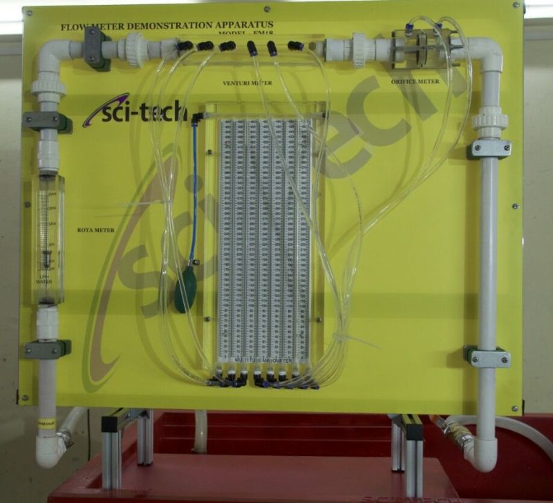
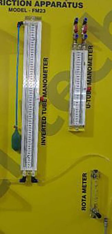
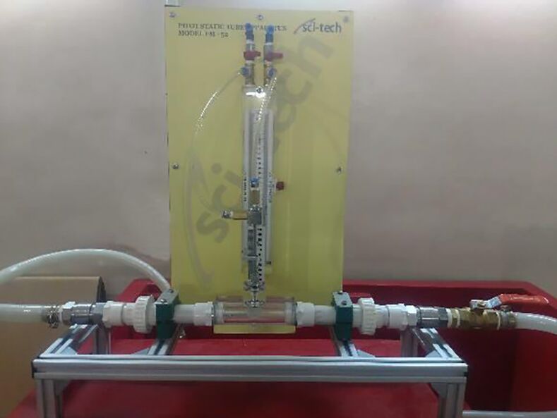
Leading Manufacturer, Supplier & Retailer of Flow Meter Demonstration Apparatus Model FM 18, orifice-meter set up, Fluid Statistics & Manometry Apparatus Model FM 56, pressure distribution venturi nozzle apparatus and Electrostatic Precipitator (ESP) Trainer Model Env 003.


Sci-tech Vapour Compression Refrigeration Air-Conditioning Trainer Model RAC 023 is an invaluable aid in the effective understanding of the air-conditioning process. The equipment is a comprehensive plant, which incorporates an axial flow fan, damper and test duct sections, flow meter, electronic control panel and loading arrangement. Temperature sensors at various points facilitate psychometric studies.
System Components
Compressor; Hermetically sealed rotary compressor; Power @ 500W
Refrigerant Type R134a or R1234yf (environmentally friendly)
Evaporator Type: Finned-tube air heat exchanger with fan
Condenser Type: Finned-tube air-cooled condenser with axial fan
Expansion Device: Capillary tube or thermostatic expansion valve (TEV)
Evaporator Air Flow: 100 300 m/h with adjustable speed fan
Condenser Air Flow: 100 300 m/h with adjustable speed fan
Working Pressure Range: 1 to 12 bar (depending on refrigerant)
Temperature Range: -5C to 50C air temperature
Instrumentation (11: Touch Screen Display):
- Pressure sensors (P) at key points (evaporator inlet/outlet, condenser inlet/outlet)
- Temperature sensors (T) at same points
- Refrigerant flowrate sensor (optional)
- Airflow velocity sensor (optional)
- Power meter (compressor electrical input)
- Energy consumption (kWh counter)
- Date and time display
Control Interface: Basic digital control (ON/OFF, fault reset, fan speed control)
Sci-Cal computer interface & DAQ with LabView Data Logging (Optional)
Safety Features: High/low pressure cutouts, overheat protection, electrical fuse, refrigerant sight glass
Frame/Structure: Aluminum profile or powder-coated steel frame with Casters
Transparent acrylic guards for visibility
Optional
Computerised AC trainer
Experiments
Study of a typical air-conditioning cycle
Humidification and dehumidification
Heat balance at evaporator, condenser and the overall system
Compressor efficiency at various loads
Psychometric charts
Determination of coefficient of performance
Re-circulation of air
Additional Information:
Payment Terms : T/T
Delivery Time : 8 weeks

Study of power generation using steam boiler and performance of steam generator is
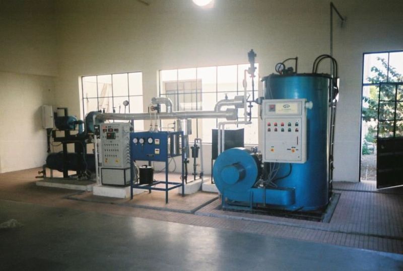
focus of this trainer. Sci-tech 1.5KW Steam Power Plant Model BSG 002, is designed the system in such fashion that enables students to investigate all the parameters governing the utilization & maintenance of a typical power plant. The system uses a small sized boiler unit that runs on LDO/gas. The generated steam is then used to run the steam turbine which in turn, runs the coupled A.C. Generator to produce the electricity or loading can be done by using Alternator & Bulb bank. A loading arrangement is also given for load test. The unit is fitted with a colored mimic diagram that illustrates the constructional and operational features. The various aspects of boiler and turbine operation and maintenance can be studied. Instrumentation is provided to measure Temperatures and Pressures. Temperature pressure characteristics of boiler can also be plotted.
System Components
Boiler 200 Kg/Hr at 11 bar
Single-stage Steam turbine with Curtis wheel and hydraulic speed regulator: 1.5 KW @ 3000RPM
Fuel consumption: 12L/h
Heat-up time: 8min
Max. pressure: 13bar
Heater: power 24 KW (In case of Electrically fired Steam Generator)
Condenser Shell & Tube Type.
Pressure measurements: 3 x 0 to 16 bar; 2 x 0 to 4 bar; 1 x -1 to 1 bar
Chimney
Orifice meter
Control valve: Electric Solenoid Type
Pump Centrifugal pump: 23 HP capacity & Piston Reciprocating Pump.
Flow meter: Flow rate 0 to 160L/min (Cooling)
Water Softener (Optional)
Steam Calorimeter- Separating & Throttling calorimeter
Temperature Indicator: 12 channel input: K Type thermocouple
Fuel supply system: Volumetric Type capacity 50Liter
K Type Thermocouple temp. Sensor
Temperature measurements: 12 x 500 to 4000C; 1 x 0 to 1000C
Torque measurement: 0 to 10 Nm
Digital Tachometer 0 -9999rpm.
Voltmeter 0-500 V.
Ammeter 0-10 Amp.
Loading arrangement- Electrical Alternator
Lamp Bank
Control panel
Cooling Tower (Optional)
Computerized Data Acquisition System
Options
Super Heater
Blow Down Tank
Sci-CalRComputer Control Software & Interface
Additional Information:
Payment Terms : T/T


Sci-tech has designed the system in such a fashion that easily operated demonstrated & requisite experimentation can be performed. Sci-tech provides a comprehensive unit; The Sci-tech Boiler Drum Simulation Trainer Model BSG 003 is able to exhibit realistic response times, uses standard industrial process instruments and process equipments and designed to study the response of type 0, 1, and 2 control system. It is a P.C. based system with visual display of the process on the monitor screen. The software used in this system is a windows-based software and is completely menu driven for experimentation. Visual display of MIMIC is provided with this system and graphics is viewed on monitor screen. Printing of data in tabular and graphical form is provided.
Sci-tech Boiler Drum Simulation Trainer Model BSG 003 is able to perform Level Studies and Shell & Tube heat Exchanger Studies function. In Level Studies the level transmitter is capable of measuring drum level in open or close tank application using the differential pressure method or other suitable method
A heater is provided to heat up water in the drum and act as energy input to the boiler.
Level switch installed in the boiler drum to cut off the electric heater if drum level is low-pressure transmitter must be provided to measure the pressure.
In Shell and Tube heat Exchanger Studies consists of two main circuit: Hot water Circuit and Cold water Circuit
SYSTEM FEATURESv Compact, comprehensive sturdy design
v Full instrumentation for experimentation on boiler control system.
v A pilot plant of boiler
v High - speed dynamic signal acquisition is possible.
v Menu driven screens with comprehensive HELP menu
v Displays graphically both on-line and historical trends
v PC based system.
v System having all process indication in color mimics.
v System is able to exhibit realistic response times, use standard industrial process instruments and process equipment
v System having facility of on line measurements for boiler drum level, feed water in flow, hot water outflow, drum pressure hot and cold water circuit temperature for heat exchanger and other instrumentations.
v Temperature, level and pressure indicator are provided for indication.
v Rota-meter is provided to measure flow rate.
v Air release valve is provided to release excess pressure to atmosphere, in case for over-pressure in the boiler drum for safety purpose
v Pressure and temperature gauges are provided.
v Provided with Alarm Annunciation
v Provided with Fault Stimulation Switches
v Powder coated structured is provided.
Additional Information:
Payment Terms : T/T

Sci-tech Utility Boiler Model BSG 004 is a typical drum-type boiler widely used in the oil refinery and petrochemical plants for steam generation.
Sci-tech Bench Top Utility Boiler Simulator Model BSG 004 is designed to demonstrate the thermodynamic basic principles of boiling phenomenon.
BSG 004 enables user to study the fundamental pressure- temperature relationship of saturated steam in equilibrium with water.
The Boiler consists of a stainless-steel pressure vessel fitted with a high pressure immersion electrical heater.
It comes with a safety valve, temperature sensor and Bourdon type pressure gauge. Water inlet valve and discharge valve are also installed.
BSG 004 comes with transducers for temperature and pressure for students to enable to take readings for respective values on a digital indicator.
Heater power supply is controlled through control panel. The heater is protected from burn-out by setting the maximum operating temperature on the temperature controller.
Optionally Data Acquisition System can be offered for Data Logging; Signal Analysis; Process Control; Real-time Display; Tabulated Results & Graph of Experimental Results
The highlights of Utility Boiler Simulator
Specification
Capacity: 5 50 liters
Material: Stainless steel (304 or 316)
Type: Bourdon type
Range: min. 0 to max. 20 bar
Range: min. 0 to max. 200 C
Temperature and pressure
Max. 5 15 bar
Power: 2 20 kW
Type: Immersion type
Thermocouple/PT100 input
Temperature controller: pressure relief valve
Electronic signal conditioning system
Windows based software:
- Data Logging
- Signal Analysis
- Process Control
- Real-time Display
- Tabulated Results
- Graph of Experimental Results
Additional Information:
Payment Terms : T/T
Delivery Time : 8 weeks

Sci-tech Computer Interfaced Continuous Distillation Column Model BSG 007 has been developed to permit the students to study the fundamentals of a continuous distillation system encountered in modern industrial processes. The solution to be distilled is stored in the feed tank. The solution is pumped from the feed tank via the feed metering pump. The distillation column consists of re-boilers, glass column sections, column packing, four packing support plate assemblies, reflux separator assembly, condenser and cap assembly. The distillate feed consists of a reflux three way control valve, distillate spiral cooler, and distillate storage tank. The residue feed comes from the re-boilers through the residue spiral cooler to the residue storage tank. The distillate of the residue may be pumped back into the feed tank for reprocess. Sampling ports are provided on all packing support plates, feed input, feed output, reflux, distillate tank, residue tank, and re-boiler. Thermocouples are used to take all temperature readings
Sci-CalR Data Acquisition Software provides real time data on computer screen along with graphs & tabular results.
Detailed Operation & Maintenance Manual is provided along with the trainer.
Experiment Capabilities
Pressure drop across the column as a function of boil-up rate.
Column efficiency as a function of boil-up rate, at total reflux
Binary mixture separation of components with changes in the feed flow rate, feed temperature, reflux ratios, and re-boiler temperatures.
Comparing Raoult-Dalton Law using the method of McCabe-Thiele
Taking samples and performing appropriate analytical procedures.
Distillation at constant reflux ratio: variation of top product composition with time
Mass balance across the system
Technical Specifications
Additional Information:
Payment Terms : T/T
Delivery Time : 8 weeks

Sci-tech Marcet Boiler Model BSG 008 is designed to study the relationship between the temperature and pressure of the steam. Marcet Boiler is made of heavy-duty stainless steel shell. It has a Mercury thermometer for readout of temperature inside the boiler. A water heater has been provided as a heating element. Heater control device also has been provided. The panel will be housed in the Tripod for easy indicator / readout.
Specifications
1. Measuring a vapour pressure curve for saturated vapour
2. Stainless Steel Pressure Boiler with insulating jacket
3. Temperature limiter and safety valve protection against overpressure in the system
4. Bourdon tube pressure gauge to indicate pressure
5. Digital temperature display
System Components
Safety valve,
Boiler with insulating jacket,
Bourdon tube manometer,
Switch box with temperature display,
Drain valve,
Heater,
Overflow Valve,
Temperature sensor
Optional Sci-Cal Sci-tech software for data acquisition via USB under Windows 7, 8.1, 10
Technical Specifications
Insulated vessel (water boiler); material: stainless steel, capacity: 2 L. approx.
An immersion heating element (computer controlled), power: 2000W., limit of the maximum heating temperature: 200C.
A security valve and a high-pressure switch to limit the working pressure to 18 bars.
For safety purposes, a pipe with a regulation valve, situated in the lower side of the boiler allows the boiler, to be filled with water using a hose. Another pipe with a regulation valve, situated in the upper side of the boiler, allows the checking of the water level using a hose. Both pipes allow the draining of the water from the boiler and to direct any vented steam away from the working area to a suitable drain.
A "J type " temperature sensor to measure the steam temperature at the water boiler.
One pressure sensor to measure the steam pressure at the boiler, range: 0-25 bar.
This unit is protected by transparent sheets with orifices to allow handling the valves.
A PID control enables to get a constant saturated steam temperature with the heating element.
Measuring Ranges:
Safety Valve: 20 bar
Dimensions: 600Lx400Wx700H in mm
Weight: @ 35 Kgs
Optional
Sci-CalR Computer Control Software
Experiments
Study of Boiler (Study type experiment)
Study of relation between pressure and temperature of wet steam may be found
experimentally.
Variation of saturated steam pressure with temperature
Confirmation of the Antoine equation
Additional Information:
Payment Terms : T/T
Delivery Time : 6 weeks
Sci-tech Rankine Cycle Steam Turbine Model BSG 012 is used to drive bulb loads or for heating system. Steam generators and steam engine together form a steam power plant. Steam power plants work according to the Rankine cycle which is still one of the most important industrially used cyclic processes. Steam power plants are mainly used for electrical power generation. The steam generator and the axial steam turbine together form a complete laboratory-scale steam power plant. Sci-techRankine Cycle Steam Turbine Model BSG 012trainer serves to familiarize students with the components and principle of operation of a steam generator and enables them to examine the characteristic values of the system. The numerous safety devices of the steam generator can be tested and checked using various monitoring devices. If the steam generator is operated without the steam turbine, the generated steam is directly liquefied in a condenser and fed back into the evaporation circuit via a tank. As all components are clearly arranged on the front panel, the cyclic process can be easily monitored and understood. Sensors record the temperature, pressure and flow rate at all relevant points. The measured values can be read on digital displays. At the same time, the measured values can also be transmitted directly to a PC viaUSB. Optionally Sci-CalR data acquisition software DAQ or SCADA can be included. The steam generator has been constructed according to the Technical Regulations for Steam, pressure-tested and is equipped with all legally required safety devices. Shown below is an example model of a steam turbine system based on the Rankine Cycle. The cycle includes superheating and reheating to prevent condensation at the high-pressure turbine and the low-pressure turbine, respectively. The cycle also has regeneration by passingextracted steam through closed feed-water heaters to warm up the water and improve cycle efficiency. The Saturated Fluid Chamber block models a separate saturated liquid volume and saturated vapor volume and is used to create the boiler and the condenser Specifications 1) Boiler: Independently certified electric boiler with manual control, pressure switches, safe pressure cut out and large capacity relief valve Rated Steam generation@ 100 DegreesC: 100Kg/Hr Steam Pressure: 10Kg/cm sq. SteamTemperature: 184 degrees C Efficiency:@ 85 90% Heater: a) Electrical Heaters @ 18KW b) Fuel: Propane consumption@ 5.5Kg Hr Heater or Burner: ON/OFF Electrical Power: 400440V, 3 Ph, 50Hz OR 200V, 3 Ph, 60Hz Feed Water Pump: 0.38KW Burner Motor: 0.20KW - Boiler Coil (Pressure Parts) (W.P.@10Kg/cm2): Vertical, Coil Type, three pass Design. Fabricated out of SS304 Tubes. Hydraulically tested at 20 Kg/cm2 - Shell Assembly:Insulated with Mineral Wool & cladding with CR sheet. - Base Frame: Fabricated in MS - Economizer: Fabricated from SS304, plates & pipes - Backfire Relief Valve: Reputed make, to release gases at the time of back firing. - Burner assembly: Long lasting - Steam Pressure Gauge: Wika/Baumer make or provision for sensor for digital signalling to computer - Feed Water Pump:Reciprocating Type with surge suppressor.Variable Pulley- With this pulley we adjust the feed water accurately which results in less condensate & good quality of steam. - Mountings & Fittings:Main Steam Stop valve- 20NB- 1 no Auxiliary steam stop valve- 15NB- 1 no Safety valve- 15NB- 1 no Non-return valve on feed water line- 15NB- 1 no Blow down valve-1 no Water Relief Valve (for Feed Water Pump Safety) - 1 no. Parts meeting water / steam will be as follow:Coil- SS304, Water Pump- Brass, Stea
Additional Information:
Payment Terms : T/T
Delivery Time : 12 weeks
In a biogas plant, microorganisms biologically depredate the organic starting substances (substrate) under exclusion of light and oxygen. The product of this anaerobic degradation is a gas mixture, which primarily consists of methane. This gas mixture is called biogas. The experimental Sci-tech Biogas Plant Model BSG 014 serves to demonstrate the generation of biogas in a practical manner. The substrate is a suspension of shredded organic solids. It is hydrolyzed and acidified in the first stirred tank reactor. Here, anaerobic microorganisms convert the long-chain organic substances into short-chain organic substances. The biogas forms in the second stirred tank reactor in the last step of the anaerobic degradation. It contains mainly methane and carbon dioxide. This two-stage method enables the ambient conditions to be adjusted and optimized in both reactors separately. The digestate is collected in a separate tank. Temperature and pH value are controlled in both reactors. The resulting biogas is dried in a column. The column is filled with silica gel. Subsequently, the flow rate, humidity, methane content, carbon dioxide content and temperature of the biogas are measured. The system is controlled by means of aSci-CalR PLCwhich is operated via a touch screen. The measured values can be transmitted to a PC viaUSBand analyzed with thesoftware. The experimental plant enables both a continuous and a discontinuous (batch) operation mode. Anaerobic biomass from a biogas plant is required for the experiments. E.g. potatoes or maize can be used to produce the substrate. An inert gas (e.g. carbon dioxide) is required to flush the experimental plant. Specifications 1. Two-stage biogas plant (continuous or discontinuous operation possible) 2. 2 stirred tank reactors made of stainless steel with capacitive level sensors 3. Separate supply unit with substrate tank and feed pump 4. Control of temperature and pH value in the reactors 5. 2 metering pumps for acid and caustic 6. Heating water circuit with tank, heater, temperature controller and pump 7. Biogas is dried with silica gel 8. Biogas analysis: flow rate, methane content, carbon dioxide content, humidity and temperature 9. Control of the experimental plant using aSci-CalR PLC, operated by touch screen 10. Optional Software for data acquisition viaUSBunder Windows 7, 8.1, 10 Technical Specifications Tanks made of stainless steel Reactor (stage 1): approx. 20L Reactor (stage 2): approx. 70L Substrate tank: approx. 25L Digestate tank: approx. 25L Pumps 3 peristaltic pumps: each max. 25L/h 2 metering pumps: each max. 2, 1L/h Heating water pump: max. 480L/h Stirring machines Substrate tank: max. 200min-1 Reactors: each max. 120min-1Measuring ranges Methane content: 0100%, Carbon dioxide content: 0100% Flow rate (biogas): 030NL/h pH value: 2x 114 Humidity: 0100% Temperature (reactors and biogas): 3x 0100C Optional: Sci-Cal Computer Control Software & Interface Sci-Cal software & hardware has been designed for use with more than 200 Sci-tech trainers. Sci-Cal comes in a module that can be fitted or mounted on the Sci-tech trainers very easily. Sci-Cal box has 10 inches front HMI interactive panel, inside are i3 processor computer with its own hard drive & software processor with 16 to 32 analog and 16 to 32 digital signal data-loggers. The Labview processes the input signal with in-built data and formulae to tabulate results for the Sci-tech trainers. Sci-Cal box has HDMI output for connection to a projector or an electronic whiteboard or a monitor. Sci-Cal box has input ports for inputs from the Sci-tech trainer sensors. Sci-Cal eliminates requirement of external computer. Experiments: Achieving a stable operating state Influence of the following parameters on the biogas generation o temperature o substrate o volumetr
Additional Information:
Payment Terms : T/T

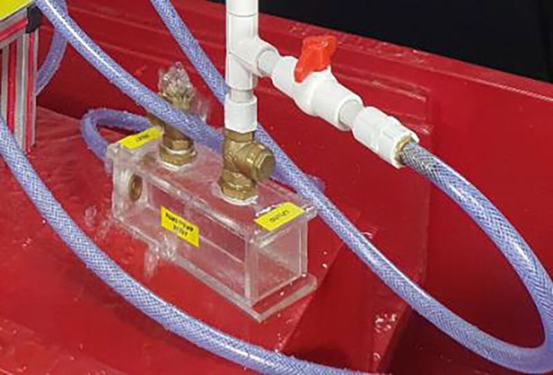
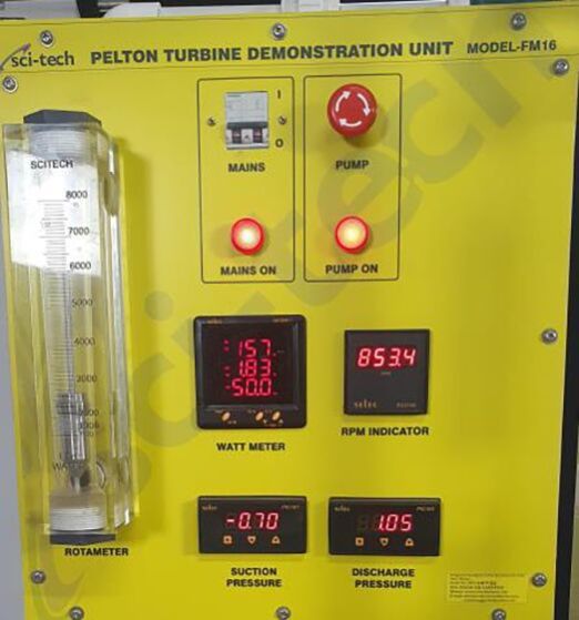
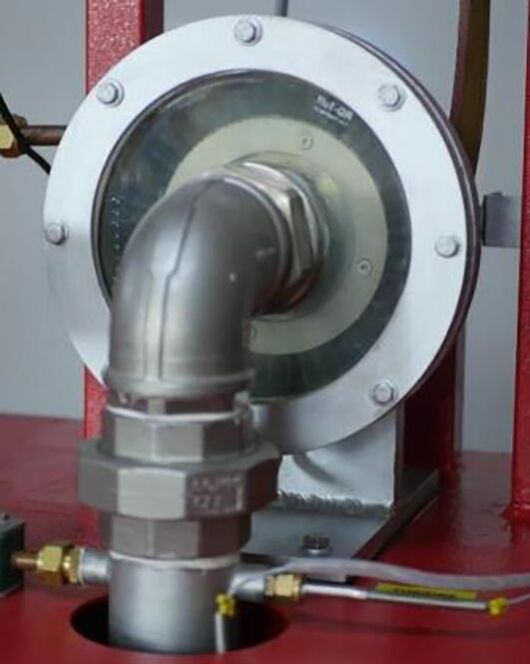
Energy saving and environmental pollution reduction are crucial global issues. Using renewable energies as alternative sources to fossil fuels can address both issues, with great benefits especially in countries where traditional energy sources are scarce. Sci-tech Hydro-Electric Power Plant Model BSG 017 enables experimental investigation on the conversion of hydraulic energy into electricity by means of a Pelton turbine. The system configuration is stand- alone (isolated from the grid). The equipment is manufactured using real components available on the market. Operating Principle If no load is connected to the system, all the produced energy is dissipated in air or used to charge the battery pack, to be ordered separately. In case some loads are connected to the system, the produced energy partially feeds the loads and partially charges the battery pack (optional item) or is dissipated in air. When the consumption is higher than the power available from the water, the power surplus is given by the battery pack (optional item). The system consists of: A) Mini hydroelectric power plant mounted on castors including: 1) Turbine-generator unit with water distributor2) Variable speed centrifugal pump3) Stainless steel water tank 4) Flow rate sensor5) Pressure sensor and pressure gauge B) Table top control panel including: 1) Controller with air dissipation system 2) Sinewave inverter 3)Electric loads 4) Electric instrumentation for detecting the energy flows in different branches of the circuit 5) Sci-CalR Data acquisition board with USB interface for PC connection TECHNICAL SPECIFICATIONS Mini hydroelectric power plant mounted on castors: Turbine-generator unit:- AISI 304 stainless steel Pelton turbine, d = 100 mm, blade no. = 20- 6-jet distributor- 3 jets can be externally intercepted- permanent magnets synchronous generator - rated voltage: 25 VAC Three phase - frequency: 200 Hz- nominal electric power output: 0, 5 kW (height 30 m, flow rate 3 l/s)- generator speed: 3000 rpm AISI 304 stainless steel horizontal axis multistage mono-block pump: - power: 0, 75 kW- maximum flow rate: 10 m3/h- maximum head: 43 m- frequency converter for rpm adjustment AISI 304 stainless steel water tank, capacity: 250 liters AISI 304 stainless steel hydraulic circuit feeding the turbine- generator unit with:- ball valve and dial vacuum gauge, range: -1 5 bar, at pump suction- dial pressure gauge, range: 0 6 bar, and gate valve at pump discharge- ball valve at distributor-tank by-pass Flow rate sensor for measuring and transmitting the water flow rate to the control panel Transducer type: rotating vane Range: 25 250 liters/minute Pressure sensor for measuring and transmitting the water pressure to the control panel Transducer type: piezoresistive Range: 0 16 bar Table top control panel: Steel structure with:- front side: comprehensive colored diagram of the system- back side: AC loading system consisting of 5 x 30 W (equivalent) switchable lamps Controller - Rectifier- Air dissipation system- Digital voltmeter for the DC parameters - Digital ammeter for the DC parameters Inverter- continuous output power: 600 W- peak output power: 1200 W- input voltage: 24 Vdc- output voltage: 230 Vac - 50 Hz- output waveform: modified sine wave- stop for low battery charge- protection against overload, short circuit, overtemperature Instrumentation- multifunction instruments, microprocessor-based, for AC parameters Socket for connection to the spotlight AC 220V Sci-CalRPC data acquisition Parameters displayed:- All DC and AC parameters - Water pressure and flow rate The software enables to: - Calculate the hydraulic energy conversion efficiency o - Visualize the energy flows to and from turbine-generator unit, battery pack (if present) and inverter o - Draw the characteristic curve efficiency / flow rate to find out the point of maximum performance of the turbine- generator unit Experim
Additional Information:
Payment Terms : T/T
Delivery Time : 12 weeks
In many the chemical and foodstuffs industries, ethanol (alcohol) is increasingly used as a fuel. Sci-tech Bio Ethanol Plant Model PT 011 can be used to conduct realistic experiments for the production of ethanol from starch-based raw materials such as potatoes. The experimental plant consists of three main components: a mash tank, a fermentation tank and a distillation unit.
A mixture of water, finely chopped potatoes and alpha-amylase (enzyme) is filled into the mash tank. To dissolve the tightly packed starch chains in the potatoes, heating steam is injected into the mixture via a nozzle (gelatinisation). This increases the flow resistance of the mash, which would prevent further processes. The alpha-amylase breaks up the starch chains (liquefying) thereby reducing the flow resistance. Gluco-amylase is used to convert the starch into sugar (saccharification). This enzyme requires lower temperatures and pH values. The temperature is reduced using the water cooling jacket around the mash tank, the pH value is adjusted by the addition of acid and caustic. After saccharification the mash is pumped into the fermentation tank. During the fermentation process in this tank, ethanol is produced. A water cooling system controls the temperature. After the fermentation process, the mash is pumped into the distillation unit. This is equipped with a bubble cap tray column for separation of the ethanol. Two tanks are available, one for the spent mash, the other for the distilled ethanol.
The experimental plant has comprehensive measurement, control and operating functions, which are controlled via aPLC or DAQ. An optional touch screen displays measured values and permits the operation of the system.
The steam supply occurs via laboratory network or an optionally available electrical steam generator Sci-tech Model BSG 010
Specifications
1. Batch conversion of starch-based raw materials into ethanol
2. Open mash tank with water-jacket cooling, steam injection and stirrer
3. Closed fermentation tank with stirrer and water-jacket cooling/heating
4. Distillation unit with 3 bubble cap trays, dephlegmator, condenser and stirrer
5. 2 pumps for delivering the mash
6. pH value control in the mash tank with acid and caustic delivered by metering pumps
7. Adjustment of the amount of injected heating steam, the cooling water flow rates and the head
temperature by means ofPID / DAQ controllers
8. System control using aPLC or DAQ; operated by optional touch screen
9. Sci-techsoftware for data acquisition viaUSBunder Windows 7, 8.1, 10
Technical Specifications
Mash tank: 40LFermentation tank: 50LProduct tank: 10LSpent mash: 30LDistillation unit
column: DxH: 220x1200mm
sump capacity: 45L
sump heater: 07500W
2 air-operated diaphragm pumps
drive pressure: 2bar
max. flow rate: 15L/min
max. head: 20m
max. solid lump size: 4mm
2 metering pumps (acid and caustic)
max. flow rate: each 2, 1L/h
Measuring ranges
temperature: 10x 0150C
water quantity mash tank: 020L
pH value: 210
pressure heating steam: 010bar
Accessories
PC with Windows (OPTIONAL)
1 set of enzymes etc., 1 set of accessories, 1 software + USB cable, 1 set of instructional material
Electrical steam generator 12kW (steam (10kg/h, min. 3bar)
Experiments:
Familiarization with the necessary individual steps and system components for production of
ethanol:
Gelatinisation by steam injection
Liquefaction by use of alpha-amylase
Saccharification by use of gluco-amylase
Fermentation: conversion of sugar into ethanol by yeast cultures under anaerobic
conditions
Distillation: separation of ethanol from the mash
Additional Information:
Payment Terms : T/T
Delivery Time : 24 weeks
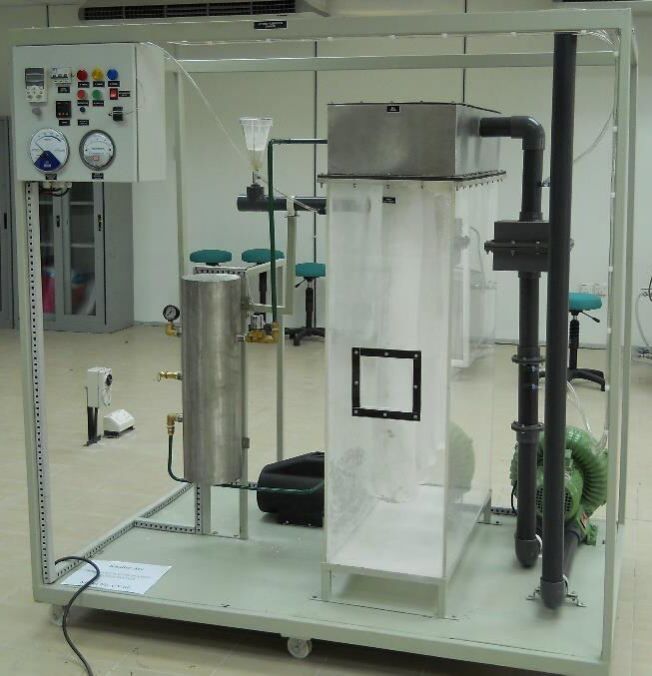
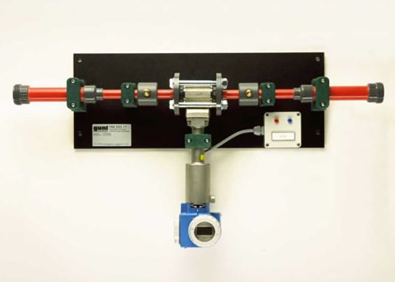
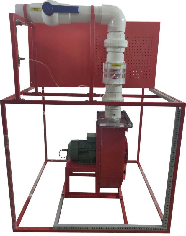
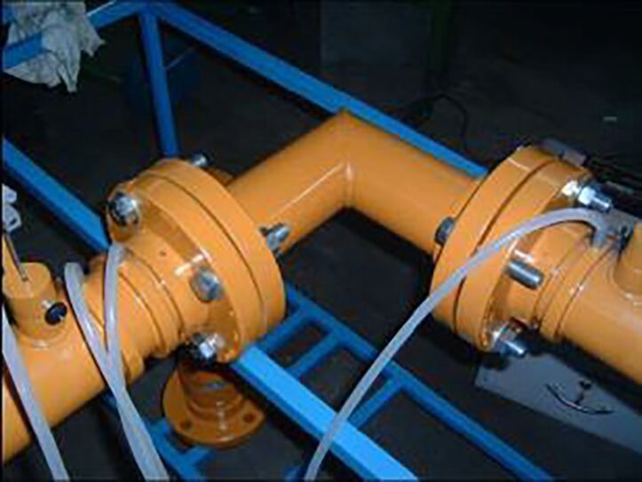
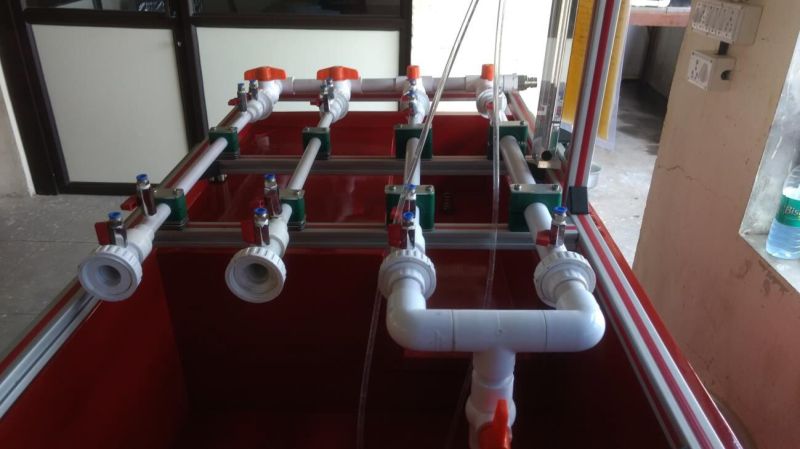
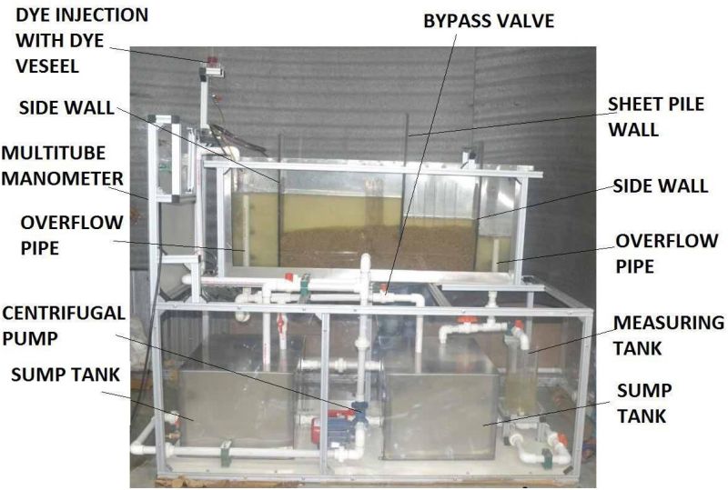
Sci-tech Cyclonic Separation Trainer Model ENV 001 is a method of removing particulates from an air stream through a vortex separation process. A high speed forced vortex rotating air flow is established within a cylinder called a cyclone. Cyclones are used widely in sawmills to remove saw dust from extracted air as well as oil refineries to separate oils and gases. This Cyclone Separation Trainer is used for demonstrating the basics of cyclonic vortex separation. The apparatus comprises of four main cyclones of different diameters, a dust feed system and an air supply blower. A venturi type flow meter is provided to measure the incoming air flow rates. Each cyclone is fitted with a particle collector for dust collection. Cyclones can be run individually or in series of any two. Air flow rates can be varied by controlling the air blower speed. A dust tank is provided to inject the dust into the system. Differential pressure measurement for individual cyclones is provided to measure the pressure drop across the cyclone and hence the velocity of air in the cyclone can be determined.
Sci-tech Cyclonic Separation Trainer Model ENV 001 trainer consists of three cyclone separators mounted on frame. Two cyclone separators are made of steel & one is made of glass. The cyclones can be arranged in such way that either one cyclone can be operated at a time, or two cyclones can be operated in series. A high-volume air blower which draws large volume of air through the cyclone separator. A hopper with control valve is used to feed dust particles into the stream of air. The air mixed with particles then enters tangentially at the top inlet in the separator. The dust particles are separated in the separator & collected in container at the bottom. The filtered air leaves the separator through the outlet at the top. A Variable Speed Drive is used to vary the velocity & flow of air through the separator.
Each cyclone separator has glands to for measuring pressure difference across the cyclone. A differential pressure gauge is used to measure the differential pressure across cyclone. The air flow is measured by a venturi meter with differential pressure gauge.
EXPERIMENTS CAPABILITIES
Understanding of air cyclone system.
Demonstration of basic cyclonic separation
Effect of input velocity against separation efficiency
Effect of particle size on separation efficiency
Cyclone diameter and conical construction on separation efficiency
Single and double cyclone operation effects
Comparison of pressure drop against input velocity
To verify the theoretical relationship between pressure drop and inlet velocity
TECHNICAL DATA
Air Blower
- Capacity 280 m3/hr @ 3400 RPM,
- 5 hp 3 phase 415 V AC, 50 Hz
- Static Pressure: 20 kPa
- Blower Speed Control: Frequency Inverter
Cyclone Material: Stainless Steel or Borosilicate glass 2 Nos, Borosilicate Glass -1 No.
Cyclone Separator: Diameter 100 mm 1 Nos.
Cyclone Separator: Diameter 200 mm 2 Nos.
Dust Collector: Acrylic tank
Dust Feeder
Air Flow Meter: Venturimeter with differential pressure gauge
No. of dust collector tank 3 Nos.
No. of differential pressure gauges 2 Nos.
Differential Pressure Range: 0-20 in of H2
Instrumentation: Pressure drop: Manometer; Air flow rate: Venturi meter; Inverter for blower speed control
Digital Instrumentation a) 2 units of digital indicators. b) 2 units differential pressure transmitter for flow pressure drop
Mobile Steel Structure
Control Console: Coated Stainless Steel
Optional
v Sci-Cal Computer Control Software & Interface (Please refer to Sci-Cal catalog)
v Sci-calVaq Sci-techs Virtual IoT based Data Acquisition system Please refer to Sci-CalVaq catalog)
Additional Information:
Payment Terms : T/T
Delivery Time : 14 weeks
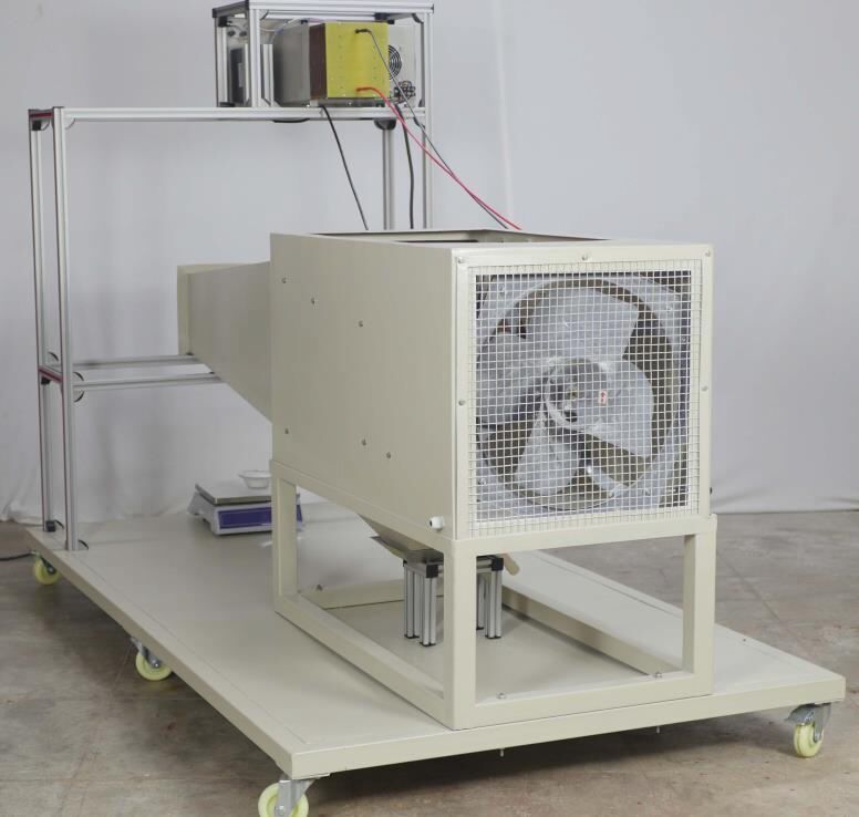
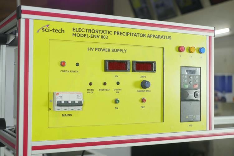
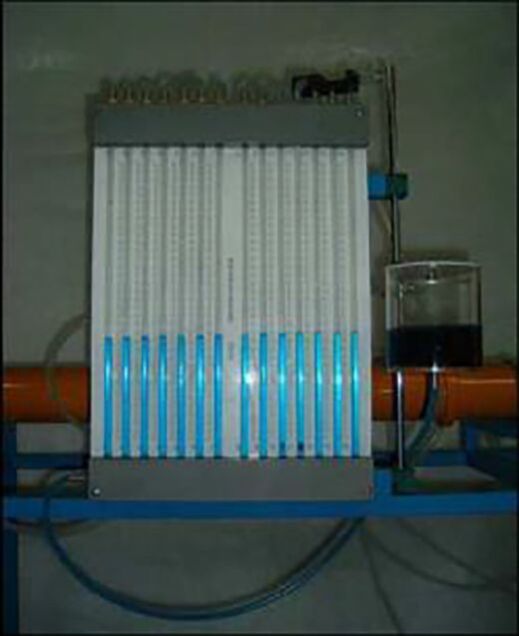
Sci-tech Electrostatic Precipitator (ESP) Trainer Model ENV 003 uses the induced electrostatic charge to remove the particles from the flow air stream. This system is designed to give the students an understanding of the electrostatic precipitator system.
The apparatus comprises of a laboratory scale electrostatic precipitator unit, dust feeding system and a digital weighing meter. A venturi type flow meter is provided to measure the incoming air flow rates.
This ESP is a plate type precipitator. It contained of a row of thin wires and followed by a stack of large flat metal plate. The air flow will flow through the thin wires and passes though the metal plate. High negative voltage is applied between the wires and plates. The ESP has a dimension of 600x1000x600mm with a fan. The operating voltage for the ionizer is about 7000 VDC while for collector is about 8000 VDC.
Air flow rates can be varied by controlling the fan speed. Dust tank is provided to inject the dust into the system. Digital weighing meter is provided to measure the dust collection by the ESP.
EXPERIMENTS CAPABILITIES
Understanding of electrostatic precipitator system
Demonstration of basic separation
Effect of input velocity against separation efficiency
Effect of particle size on separation efficiency
Effect of input charge (ionization strength) on the separation efficiency
TECHNICAL DATA
Experiment Test: Electrostatic Precipitator (ESP) System
Apparatus Frame: Epoxy coated steel frame
ESP type: Plate type
ESP size: 600x1000x600mm
Fan rating: 1/4hp TEFC motor & drive
Operating voltage: 7000VDC (ionizer); 8000VDC (collector)
Voltage Gradient: 11, 158VDC/inch (Ionizer) & 24, 768 VDC/inch (Ionizer)
Air flow meter: Digital anemometer
Hand held Anemometer range: Air velocity: 0 - 2m/s; Temperature: 0 - 65oC
Dust tank: Plexi-glass container
Digital Analytical balance: weighing capacity: 50 kg; resolution: 0.5 g;
Digital Instrumentation with (optional) sensors for digital indicators & air velocity transmitter.
Optional:
Sci-Cal Computer Control Software & Interface
EXPERIMENTS CAPABILITIES
Understanding of electrostatic precipitator system
Demonstration of basic separation
Effect of input velocity against separation efficiency
Effect of particle size on separation efficiency
Effect of input charge (ionization strength) on the separation efficiency
Additional Information:
Payment Terms : T/T
Delivery Time : 16 weeks

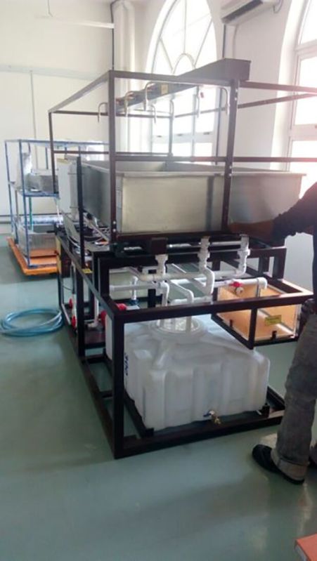
Sci-tech Automated Sludge Sewage Treatment PlantENV 004 activated sludge sewage treatment pilot plant is a small-scale industrial sewage plant. It consists of all the comprehensive components and advance process control instrument to make the trainer more interesting on study. All the tank, components, instrumentation are mounted on mobile workbench with caster roller. The bench is made of stainless-steel frame. Tabletop is made of durable ABS plastic material which can withstand the wet and chemical resistance. The main control instrumentations consist of PLC, analog data acquisition card, input and output digital module pH control, O2 controller, Redo X controller, temperature controller comprehensive aluminum etching mimic diagram with indicating light and alarm annunciator. All analysis controller is link to PC with data acquisition software. The setup of instrumentation communication is using modbus RTU RS485 which is widely used in modern sewage treatment plant. The operation status of the pump, solenoid control valve are controlled through PC Experiment Possibilities Study & measure of BOD (Biological Oxygen Demand) unit & COD (Chemical Oxygen Demand) Process of substrate flow Effect of the temperature on the purification Influence of PH and Oxygen on treatment process Air injection time The influence of dissolved oxygen concentration Sludge recirculation flow process The effect of stirrer speed on treatment process Determination of the purification effect of stay time in oxidation tank Determine the purification effect on mixing Effect of different concentration of dissolved O2 on treatment plants efficiency Determination of sludge sedimentation varying the concentration of work O2 Influence of the activated carbon on the purification process Testing using O2 instead of air (10 liter oxygen fill cylinder is provided) The control function of pilot plant consists of two modes: Fully automatic mode This model is fully automotive control by PLC (Optional SCADA), which analysis data feed back by the controller Manual mode This mode, student can commend any control sequence via the PC control software, this is to facilitate the simulation and generate various type treatment process phenomenon and faults. This to enhance the student understanding and chemical-physical problem arising from the realization of an activated sludge process. The value of the analysis carried out in laboratory (COD, BOD, MVS etc) could be set by the operator to be taken into account in the formulas of flow instruction. The process flow-line Aerobic condition of cultivates the Micro-organism Micro-organism digest the contaminated substances After the pollutant elimination phase, it is further divide into clarified water and go to settling tank The clarified water is further sterilized, while the activated sludge is partially recycled within oxidation tank in order to stabilize the treatment process. Practice provide and other training provided: The agitation effect on the treatment tank Advantage of air-lift in the sludge recirculating system Effect of oxygen concentration on the sludge elimination Technical Specifications Air line system Item Description Qty. 1 Pressure regulator, range: 0 to 9 bars 1 2 Two gas rotameters 3 Flow controller BSP 2 4 Flow control solenoid valve BSP, 24Vdc 1 5 Air distribution/diffuser for reactor 1 6 Air lift system for sludge recirculating tank 1 7 Air pump 700 I/h, 2 bar 1 Liquid line Item Description Qty. 1 Feed preparation tank with stirrer, 30 liter glass tank with stirrer and variable speed controller 1 2 Volumetric feed pump to study dilution control peristaltic pump, 230V, 50Hz, 350mA, Flowrate 1.5, 5 and 10 liter per hour adjustable by changing the tube size 1 3 Plexiglas/Glass reactor tank, 25 liters 1 4 Plexiglas/Glass settling tank with air lift, 30 liter
Additional Information:
Payment Terms : T/T
Delivery Time : 24 weeks
Sci-tech Pulsed Jet Bag Filtration Training System Model ENV 008 has been designed for demonstrating dust pollution control using a fabric filter and for investigating the effects of varying total filtration area on filtering efficiency. In addition, students can study the effects of varying gas-to-cloth (G/C) ratio between pressure drop, P and inlet velocity, vi.
The system comprises of a bag house, a pulse-jet cleaning system, a dust feeding system and a variable speed air blower. The bag house is divided into two sections: top and bottom. The top section is of stainless-steel construct, connected to the compressed air tank to form part of the pulse-jet cleaning mechanism. The bottom section is made of rigid transparent polycarbonate with dust collector. Through this bottom section, students can view the filtering.
and cleaning operations of the bag filtering system. The cleaning mechanism comprises of a compressed air tank, a solenoid valve with remote selectable timer and a portable air compressor unit. Four units of polyester fabric filters are installed in a row inside the bottom section of the bag house. An air blower installed at the outlet is capable of drawing 198 m3/hr of air through the system. The air inlet velocity can be varied by means of adjusting the air blower speed. A dust feeding system is provided for introducing a desired amount of dust particles into the air stream before entering the bag house. The pressure drop, P across the bag house can be measured by a differential pressure meter. The entire system is mounted on a skid platform with an epoxy-coated steel frame and lockable castor wheels for mobility. All the necessary instruments are housed within a dust and splash proof control console with IP 55 rating. The system comes with complete PVC piping connections.
EXPERIMENTS
Demonstration of a bag filtering system in dust pollution control
To study the effects of varying total filtering area
To investigate the effects of varying gas-to-cloth (G/C) ratio on separation efficiency
To verify the relationship between pressure, drop, P and inlet velocity, vi
TECHNICAL SPECIFICATIONS
a) Bag house
No. of sections: 2
1Top section material: Stainless steel
Dimensions: 890 mm (L) x 380 mm (W) x 200 mm (H)
Btm. section material: Clear polycarbonate
Accessories: Dust collector
b) Fabric filter
Material: Polyester
Dimensions: 13.5 cm (D) x 100 cm (H)
Mount: Support cage to prevent collapse
c) Pulse-jet cleaning system
Compressed air tank
Capacity: Approx. 20 L
Material: Stainless steel
Accessories: Pressure relieve valve 0 to 2 bar
Air compressor: Portable type 1 hp
Cleaning nozzles for each fabric filter
Solenoid valve with remote selectable timer
d) Air blower
Rated power: 2 hp
Max. air delivery: 198 m3/hr @ 2800 rpm
Max. static pressure: 69 in H2O
Speed controller: Frequency inverter
e) Air flow meter
Type: Venturi with differential pressure gauge
Material: Durable clear acrylic
DP gauge range: 0 to 16 in H2O
f) Feeding container
Material: Acrylic cylinder with conical bottom
Feed control: Rapid acting valve
g) Differential pressure
Type: Panel mounted Bourdon type differential pressure gauge
Range: 0 to 25 cm H2O
Additional Information:
Payment Terms : T/T
Delivery Time : 12 weeks

Sci-tech Spray Chamber Trainer System Model ENV 009 has been designed to demonstrate the spray chamber operations using five different spray nozzles, and for students to study the effects of droplet size on separation efficiency. Students can also investigate the effects of liquid-to-gas (L/G) ratio upon separation efficiency.
The system comprises of a spray (separation) chamber, a water circulation system, a dust feeding system and a variable speed air blower. The spray chamber is fabricated from rigid transparent acrylic measuring approximately 0.3m in diameter and 2m in height. The spray chamber can be fitted with five different spray nozzles to produce five different droplet sizes. The top of the spray chamber is equipped with a mist eliminator to prevent any water droplets from escaping. The water circulation system consists of a water tank, water pump, liquid flow meters, a pressure gauge and a pressure regulator.
An air blower installed at the outlet is capable of drawing 198 m3/hr of air through the system.
The air inlet velocity can be varied by means of adjusting the air blower speed. A dust
feeding system is provided for introducing a desired amount of dust particles into the air stream before entering the separation chamber. The pressure drop, P across the separation chamber can be measured by a differential pressure meter.
The entire system is mounted on a skid platform with an epoxy-coated steel frame and lockable castor wheels for mobility. All the necessary instruments are housed within a dust and splashproof control console with IP 55 rating. The system comes with complete PVC and stainless steel piping connections.
EXPERIMENTS
To study the effects of droplet size on separation efficiency
To investigate the effects of liquid-to-gas (L/G) ratio on separation efficiency
To verify the relationship between pressure drop, P and inlet velocity, vi
TECHNICAL SPECIFICATIONS
a) Spray nozzles
Material: Stainless steel
No. of sizes: 5
Droplet size: 100, 200, 300, 500 and 1000
b) Separation chamber
Material: Durable clear acrylic
Size: 0.3 m (D) x 2 m (H)
Accessories: Spray nozzle mount and mist eliminator
c) Water circulation system
Tank material: Stainless steel
Tank size: 55 L
Protection: Low level pump cut-off switch
Pump type: Centrifugal
Max. flow rate: 25 L/min
Flow meters: 0 to 1 L/min and 0 to 20 L/min
Pressure gauge: 0 to 6 bar
d) Air blower
Rated power: 2 hp
Max. air delivery: 198 m3/hr @ 2800 rpm
Max. static pressure: 69 in H2O
Speed control: Frequency inverter
e) Air flow meter
Type: Venturi with differential pressure gauge
Material: Durable clear acrylic
DP gauge range: 0 to 16 in H2O
f) Feeding system
Material: Acrylic cylinder with conical bottom
Feed control: Flow regulating valve
g) Differential pressure
Type: Panel mounted Bourdon type differential pressure gauge
Range: 0 to 100 mm H2O
Additional Information:
Payment Terms : T/T
Delivery Time : 12 weeks

Sci-tech Venturi Air Scrubber System Model ENV 010 s used to demonstrate dust pollution control and the effect of liquid -to-gas ratio (L/G) on separation efficiency. The system comprises of a venturi tube, separation chamber, dust feeding system, water recirculation system and a variable speed air blower.
The venturi tube is made of transparent and rigid plexi-glass for the observation of flow. A differential pressure transducer is used to measure pressure drop across the venturi. The cylindrical separation chamber is also made of transparent, rigid plexiglass with a diameter of 500 mm and height of 1.6 meter. At the side bottom of the separation chamber is a circular inlet which is connected to the outlet of the venturi. The chamber also houses a mist eliminator at the top which prevents water droplets from escaping the chamber.
A collecting plastic tank is provided to collect the mixture of dust and water at the bottom of the separating chamber.
The water recirculation system comprises of a water tank, pump, flow meter, pressure
gauge and pressure regulator. The stainless-steel water tank is located below the separation chamber and supplies water to the pump. A filter is attached to the pump inlet to prevent dust and debris from damaging the pump.
The air blower is used to draw air at a maximum rate of 300 m3/hour through the separation chamber. The inlet air velocity can be adjusted by varying the air blower speed. The dust feeding system is used to simulate pollution in the air stream before entering the separation chamber.
The systems main frame is made of welded mild steel. The frame is epoxy-coated for
aesthetics, durability and heat and corrosion resistance. A control panel is mounted on the steel frame as well to house all the electrical and electronic components.
TRAINING AIMS / EXPERIMENTS LIST
Understanding of air scrubber system.
Understanding the working principles of air scrubber system.
To demonstrate and simulate dust pollution control using a venturi scrubber.
To study the effect of air velocity and water flow rate on separation efficiency.
TECHNICAL SPECIFICATIONS
Venturi tube
Made of transparent rigid PVC for easy observation and durability
Throat ID: 30 mm
Inlet & outlet ID: 100 mm
Convergence angle: 10; Divergence angle: 5
Tappings at inlet & outlet for pressure drop measurement
Separation chamber
Made of transparent rigid plexiglass for easy observation and durability
Cylinder ID: 500 mm; Height: 1.6 meter
Tangentially connected to a circular inlet
Mist eliminator at top made of stainless steel
Plastic collecting tank at the bottom
Water recirculation system
Stainless steel tank with a capacity of 60 L c/w level switch
Centrifugal pump capable of delivering up to 25 LPM
Flow meter 0 - 10 LPM
Air blower
High pressure blower capable of delivering 300m3/hour @ 3000 rpm
Able to withstand up to 20kPa static pressure
Comes with inverter for regulating blower speed
Instruments & accessories
Venturi type air flow meter with differential pressure gauge. DP range: max 20kPa
Feeding system made of stainless-steel tank and flow regulating valve
Control Panel
Epoxy coated steel box
Water proof panel sticker
Housing for electrical and electronic components
Optional accessories
Digital indicators with selector switch (2 units)
Differential pressure transmitters (3 units)
Liquid flow meter (1 unit)
Data acquisition system
COMPONENTS LIST
Epoxy coated steel frame.
Clear plexiglass separating chamber.
Clear plexiglass venturi tube.
Stainless steel water tank.
Centrifugal pump.
Differential pressure gauge.
Frequency inverter.
Control panel.
Plastic collecting tank.
Air blower.
Flow meter.
Water filter.
Stainless steel dust tank.
Additional Information:
Payment Terms : T/T
Delivery Time : 14 weeks

Sci-tech Anaerobic Water Treatment System Model ENV 012demonstrates the biological anaerobic water treatment. The trainer consists basically of two units:- Stirring tank with secondary clarifier-UASBreactor
Both units can be used separately or in combination. This allows both a single stage and a dual stage operation mode. In the dual stage operation, a pump first transports the raw water into a stirred tank. In this tank the acidification of the organic substances dissolved in the raw water takes place. Here, anaerobic microorganisms convert the long-chain organic substances into short-chain organic substances. In a secondary clarifier the biomass discharged from the stirred tank is separated from the water. The separated biomass is pumped back into the stirring tank.
From the secondary clarifier the raw water pretreated in this manner reaches aUASBreactor (UASB: Upflow Anaerobic Sludge Blanket). Here the final step of the anaerobic degradation takes place. The previously formed short-chain substances are converted by special microorganisms into biogas (methane and carbon dioxide). Flow through theUASBreactor is from the bottom to the top. At the top of theUASBreactor there is a separation system. This separates the generated gas from the treated water. It also ensures that the biomass remains in the reactor. The gas can be discharged externally or collected. The treated water exits at the top end of the reactor and is collected in a tank.
To adjust the flow velocity in theUASBreactor a of the treated water can be re-circulated.
The temperatures in the stirred tank and theUASBreactor can be controlled. The pH value in the stirred tank is measured. In addition, the pH value in theUASBreactor can be controlled. A software and webcam are available for data acquisition and visual inspection.
Anaerobic biomass and analysis technology are required to perform the experiments. Recommended parameters are:COD(chemical oxygen demand), nitrogen and phosphor.
Specifications
1. Anaerobic degradation of organic substances
2. Stirred tank with secondary clarifier
3. UASBreactor with separation system
4. Separate supply unit with tanks for raw water and treated water
5. Single stage or dual stage operation mode
6. Temperatures in the stirred tank and theUASBreactor can be controlled
7. Control of the pH value in theUASBreactor
8. Software for data acquisition viaUSBunder Windows 7 (Optional)
9. Visual inspection with webcam (Optional)
Technical Specifications
Tanks
stirred tank: 30L
secondary clarifier: 30L
UASBreactor: 50L
tank for raw water: 180L
tank for treated water: 180L
Flow rates (max.)
raw water pump: 25L/h
return sludge pump: 25L/h
circulation pump: 100L/h
metering pumps: 2x 2, 1L/h
Measuring ranges
pH value: 014
temperature: 0100C
Optional:a) Sci-Cal SCADA Computer Control Software & Interface
Experiments:
Familiarization with anaerobic water treatment
Effects of temperature and pH value on anaerobic degradation
Functional principle of aUASBreactor
Comparison of single stage and dual stage operation mode
Monitoring and optimization of the operating conditions
Identification of the following influencing factors
o sludge loading
o volumetric loading
o flow velocity in theUASBreactor
Additional Information:
Payment Terms : T/T
Delivery Time : 16 weeks
Ion exchangers are used in water treatment primarily for desalination and softening.Sci-tech Ion Exchange Chamber Model ENV 013 enables these processes to be demonstrated with the aid of cation and anion exchangers.
The raw water is pumped from the tank into the top of the cation exchanger. In the softening process the water flows from there back into the collecting tank. To desalinate the raw water, it is then additionally routed through the anion exchanger. From there the treated water passes into the collecting tank. In the regeneration process, acid or caustic is fed into the ion exchangers from below using the same pump. The acid and caustic used is collected in the collecting tank.
The flow rate of the pump is adjustable, and can be read from a flow meter before it enters the first ion exchanger. For continuous evaluation of the process, a conductivity sensor is installed upstream of the inlet into the collecting tank. The measured values can be read from a conductivity meter. Samples can be taken at all relevant points. Tap water can be used as raw water.
Specifications
1. Softening and desalination with ion exchange
2. Cation and anion exchangers usable separately and in combination
3. Regeneration of ion exchangers
4. Tank with 4 chambers for raw water, rinsing water, acid and caustic
5. Diaphragm pump to transport raw water, rinsing water, acid and caustic
6. Collecting tank for treated water, rinsing water, acid and caustic
7. Continuous measurement of conductivity and flow rate
Technical Specifications
Ion exchanger
material: network polymer
cation exchanger: H+form
anion exchanger: OH-form
Diaphragm pump
max. flow rate: 300mL/min
max. head: 10m
Tank
4 chambers
capacity: each approx. 5L
material:PVC
Collecting tank
capacity: approx. 20L
material:PVC
Measuring ranges
flow rate: 20270ml/min
conductivity: 02000S/cm
Experiments:
Learning the fundamental principle of softening and desalination by ion exchange
Identification of the different modes of operation of cation and anion exchangers
Combined use of cation and anion exchangers for desalination
Exchanging capacities and regeneration
Verification of the theoretically calculated regeneration time
Additional Information:
Payment Terms : T/T
Delivery Time : 12 weeks

Coagulation - flocculation - settling processes are generally used to separate colloids from water, as in this case natural settling speed is too slow to obtain a sufficient clarification. Sci-tech Coagulation, Flocculation and Settling Pilot Plant Model ENV 014 enables to study the coagulation, flocculation and settling processes separately or simultaneously and it mainly consists of a stirred feed tank, of two tanks for flocculant and coagulant, of a stirred coagulation tank, of a stirred flocculation tank and of a plate settler.
Process control, data acquisition and supervision are automatically carried out by a microprocessor controller and by a specific control and supervision software that enables the remote control of various operational parameters.
Specifications
Framework of AISI 304 stainless steel with castors
Cylindrical feed tank of transparent methacrylate for the water to be treated with submersible pump and capacity of 300 l
Feed tank of transparent methacrylate for coagulant with capacity of 60 l
Feed tank of glass for flocculant, provided with hot-plate magnetic stirrer, with capacity of 0.5 l
Coagulation reactor of borosilicate glass, equipped with motor-driven stirrer (0 to 300 r.p.m.), with capacity of 30 l
Flocculation reactor of borosilicate glass, equipped with motor-driven stirrer (0 to 100 r.p.m.), with capacity of 8 l
Rectangular settler of transparent methacrylate with conical bottom and movable plates for its operation in co-current and counter-current
Flowmeter of AISI 304 stainless steel for measuring feed flow rate with range of 30 to 300 l/h
Flowmeter of coagulant feed with range of 2 to 20 l/h
Feed screw pump with casing and screw of AISI 316 stainless steel and flow rate of 0 to 200 l/h
Electronic frequency variator for screw pump
Gear feed pump of AISI 316 stainless steel for coagulant, with flow-rate of 0 to 50 l/h
Metering pump of flocculant, with flow rate of 0 to 200 ml/h
Switchboard IP55, complying with EC conformity mark, including plant synoptic and ELCB
Besides being provided with all the technical characteristics of ENV 014, this model also includes the following additional equipment:
Digital microprocessor PID controller, with two control loops
Optional Supervision software for Windows: it enables to control ON-OFF signals, analog signals coming from PID controller, real- time trend and historical trend
OPTIONAL
Sci-Cal SCADA Computer Control Software & Interface
Experiments
The process unit enables to develop and analyze the following issues:
Additional Information:
Payment Terms : T/T
Delivery Time : 16 weeks

Sci-tech Filtration Pilot Plant Model ENV 015 mainly consists of a sand filter and of an activated carbon filter; filtered water is collected into a tank of stainless steel from which samples for proper laboratory analyses can be extracted. An in-line turbidimeter enables to measure the turbidity of water flowing in and out of filters.
Process control, data acquisition and supervision are automatically carried out by a microprocessor controller and by a specific control and supervision software (only for automatic plant) that enables the remote control of various operational parameters.
Specifications
Framework of AISI 304 stainless steel with castors
Sand filter of borosilicate glass with decreasing particle size and capacity of 30 l
Activated carbon filter of borosilicate glass with capacity of 30 l
4 pressure gauges, with range of 0 to 10 m of water column
Centrifugal pump with casing and rotor of AISI 304 stainless steel and flow-rate of 3000 l/h
Variable area flowmeter of AISI 304 stainless steel, with range of 100 to 1000 l/h
Metering pump of plastic material for sodium hypochlorite, with flow rate of 3 l/h
Metering pump of plastic material for flocculant, with flowrate of 3 l/h
2 feed tanks of AISI 304 stainless steel with capacity of 120 l
Tank of AISI 304 stainless steel for collecting the filtered water with capacity of 200 l
Thermo-resistance Pt 100 with sheath of AISI 316 stainless steel
Board-type electronic temperature indicator
Connecting lines and valves of AISI 304 and 316 stainless steel
Besides being provided with all the technical characteristics of optional automatic, this model also includes the following additional equipment:
Pneumatic control valve of stainless steel AISI 316 for feed flow rate of water, Cv = 2.5
Electro-pneumatic converter (4 to 20 A / 0.2 to 1 bar)
Digital microprocessor PID controller
Electronic turbidimeter for measuring the turbidity of the water fl owing in and out of filters, with programmable range and 4 to 20 mA output signal
Supervision software for Windows: it enables to control ONOFF signals, analog signals coming from PID controller, real-time trend and historical trend
Experiments
The process unit enables to develop and analyze the following issues:
mechanical filtration
chemical filtration
main parameters affecting filtration
influence of feed flow rate on filtration
Optional automatic PID control
Optional plant supervision
Additional Information:
Payment Terms : T/T
Delivery Time : 24 weeks

Sci-tech Aerobic Water Treatment Pilot Plant Model ENV 018 is an activated sludge pilot plant consists of an oxidation reactor and of a settler according to the traditional diagram of single-stage sewage treatment process.
Biomass is oxidized in a reactor with agitator by the air blown by a compressor. The processed liquid is then sent to the settler.
The sludges settling on settler bottom are recycled by a recirculation pump into the oxidation tank.
The water flowing out of the settler is conveyed to a drain.
Data acquisition is carried out by a specific software.
Specifications
AISI 304 stainless steel framework with castors
Feed tank, 300 L capacity
Cylindrical oxidation reactor of transparent methacrylate, 60 L capacity, including an AISI 304 stainless steel
agitator with motor and air diffuser
Settler of transparent methacrylate, 30 L capacity
Peristaltic feed pump
Sludge recirculation peristaltic pump
Diaphragm compressor with body of stainless steel
Microprocessor-controlled board-type pH-meter, with range of 2 to 12 pH, 4 to 20 mA output signal
Microprocessor-controlled board-type rH-meter, with range of -1500 and +1500 mV, 4 to 20 mA output signal
Microprocessor-controlled board-type dissolved oxygen meter, with range of 0 and 20 ppm, 4 to 20 mA output
signal
Electronic flow-meter for measuring air flow rate to reactor
Optional
Sci-Cal DAQ software enables the operator to select the appropriate stage of the process and a mimic diagram with measured variables is displayed. The speed of the pump can be varied to meet the required flow rate.
Results are saved in a log, which can be viewed and manipulated with the Sci-Cal results viewer. Results can be printed or exported in a spreadsheet format, which can be opened in a wide range of packages for further analysis.
Experiments
The process unit enables to develop and analyze the following issues:
Purification efficiency versus the following parameters:
- composition of water to be treated
- residence time
- organic load
- pH in oxidation tank
- concentration of dissolved oxygen
Additional Information:
Payment Terms : T/T
Delivery Time : 14 weeks

During sorting, a solid compound is separated according to its material characteristics.
Magnetic separation is a method of sorting which utilises the magnetic ability of components of a solid compound. Magnetic separators are often used in coal and ore preparation.
Sci-tech Magnetic Separation Apparatus Model ENV 026 enables the solid compound to be separated is charged into the feed hopper. A vibrating trough conveys the compound onto a rotating, non-magnetic drum. Its speed can be adjusted by way of a potentiometer. In one area of the drum there is a fixed permanent magnet. Non-magnetizable components drop into a collector tank due to gravity. Magnetizable components adhere to the drum in the area of the magnet, are carried along and drop into a different tank as soon as they are beyond the magnetic zone. The mass flow of the feed material can be adjusted by way of the distance of the hopper outlet from the vibrating trough and by the throw and frequency of the trough. A mixture of sand and small steel items, such as hexagon nuts, is recommended and supplied for use as the feed material
Specifications
1. Drum-type magnetic separator for separation of magnetizable components from a solid compound
2. Separation by a fixed permanent magnet in an area of a rotating, non-magnetic drum
3. Feed hopper with vibrating trough for feed of solid compound to drum
4. Dosage of feed material by way of distance of hopper outlet from vibrating trough, throw and frequency of vibrating trough
5. Drum rotation speed adjustable by electric motor with potentiometer
6. 2 steel tanks for separated fractions and 1 tank for solid compound
7. Feed material: sand and hexagon nuts
Technical Specifications
Feed hopper capacity: 25L
Mass flow: 100 to 150 Kg/Hr as required
Vibrating trough
throw: 0, 21, 5mm
vibration frequency: 50Hz or 100Hz
Rotating Drum
Magnetic Field Range: 1800
220mm
length: 300mm
magnetic field range: 180
speed: 030 rpm
speed adjustable: via potentiometer or optionally through computer interface
Motor
power consumption: 250W
Max. particle size
non-magnetic: 20mm to 30mm
magnetic: 20mm to 30mm
Tanks
2x 15L
1x 20L
Body:
Mild steel (Optional SS304)
Portability through lockable wheels at the base
Optionally, Sci-tech offers Sci-Cal software for data acquisition and an educational software.
Experiment Possibilities
1. Familiarization with the fundamental principle and the method of operation of a drum-type magnetic separator
2. Efficiency of separation process dependent on
3. Mass flow of feed material
4. Mixing ratio of feed material
5. Type of feed material
6. Drum rotation speed
Additional Information:
Payment Terms : T/T
Delivery Time : 12 weeks
Sci-tech Three Phase Crude Oil or Drilled Crude Horizontal Separator Apparatus Model ENV 028 is designed as horizontal, but also available vertical pressure vessel (Model ENV028V). Above figure is a schematic of a horizontal separator. The fluid enters the separator and hits an inlet diverter. This sudden change in momentum does the initial gross separation of liquid and vapor as in a Two-Phase Separator. In most designs, the inlet diverter contains a downcomer that directs the liquid flow below the oil/water interface. This forces the inlet mixture of oil and water to mix with the water continuous phase in the bottom of the vessel and rise through the oil/water interface. This process is called water-washing, and it promotes the coalescence of water droplets which are entrained in the oilcontinuous phase. The inlet diverter assures that little gas is carried with the liquid, and the water wash assures that the liquid does not fall on top of the gas/oil or oil/water interface, mixing the liquid retained in the vessel and making control of the oil/water interface difficult.
The liquid collecting section of the vessel provides sufficient time so that the oil and emulsion form a layer or oil pad at the top. The free water settles to the bottom. Figure illustrates a typical horizontal separator with an interface controller and weir. The weir maintains the oil level and the level controller maintains the water level. The oil is skimmed over the weir. The level of the oil downstream of the weir is controlled by a level controller that operates the oil dump valve. The produced water flows from a nozzle in the vessel located upstream of the oil weir. An interface level controller senses the height of the oil/water interface. The controller sends a signal to the water dump valve thus allowing the correct amount of water to leave the vessel so that the oil/water interface is maintained at the design height. The gas flows horizontally and out through a mist extractor to a pressure control valve that maintains constant vessel pressure. The level of the gas/oil interface can vary from half the diameter to 75% of the diameter depending on the relative importance of liquid/gas separation. The most common configuration is half full, and this is used for the design equations. Similar equations can be developed for other interface levels.
Specifications
1. Mixture Tank Material: Poly-carbonate Cylinder
2. Mixture Tank Dimensions: 900mm L X 300mm Diameter.
3. Oil Tank: @ 50 Litres
4. Water Tank: @ 50 75Litres
5. Oil & Water Tanks: 304 SS
6. Oil Pump: Geared 1/HP, 10 LPM
7. Water Pump: Centrifugal Pump, HP, 100 LPM
8. Air Compressor/Pump: 0.75HP, 100 LPM
9. Pressure Relief Valve, SS, 010 Bar
10. Optional DAQ interface Flow Sensors, Pressure Sensor, & Temperature Sensor.
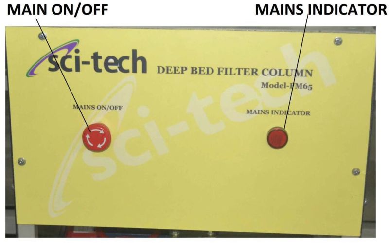
11. Control Panel
a) Optional 11 Touch Screen HMI for measurements & Control
a) Mains ON/OFF MCB
b) Oil, Water & Air Pump Mushroom Switch ON/OFF with LED indicators.
c) Optional VFDs for control of Oil, Water & Air Flow.
Optional: Sci-tech Three Phase Horizontal Separator Model ENV 028 with Wireless Wi-Fi controlledavailable with:
a) DAQ interface as model ENV 028-DAQ
b) PLC controlled model as ENV-028-PLC
c) SCADA controlled model as ENV 028-SCADA
Experiments
1. Control of oil/water/gas mixture flow control and measurements of time for separation of oil from water while monitoring pressure and temperature of the tank.
2. Repeat of process at different flow measurement speeds.
3. Obtain a desired oil pad height using equations.
Additional Information:
Payment Terms : T/T
Delivery Time : 12 weeks

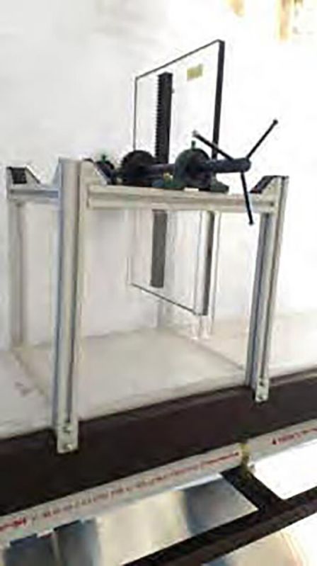
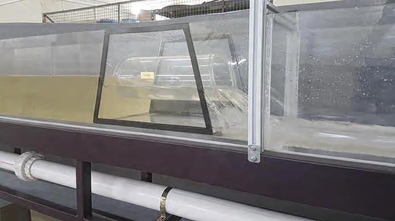
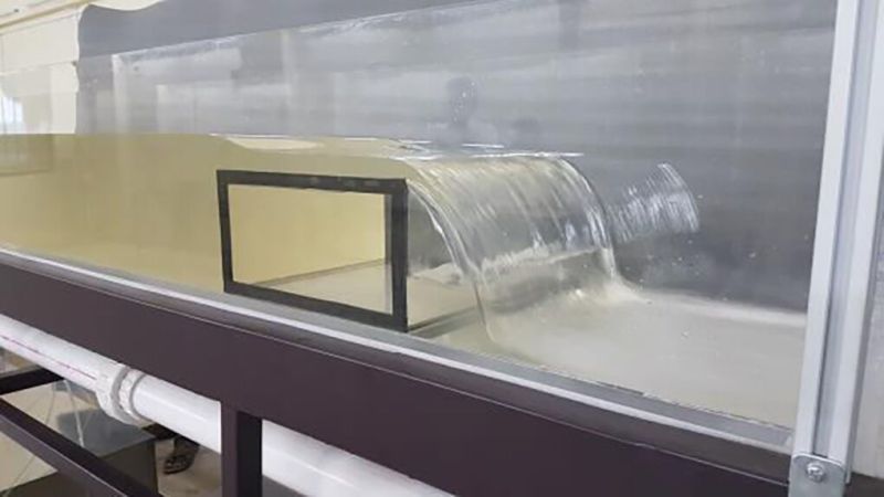
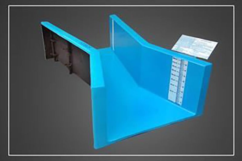
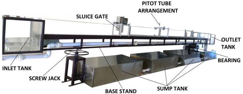
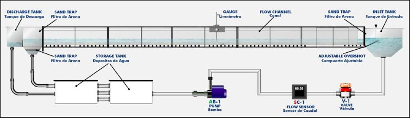
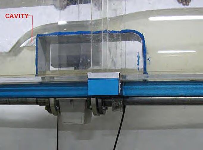
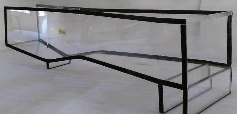
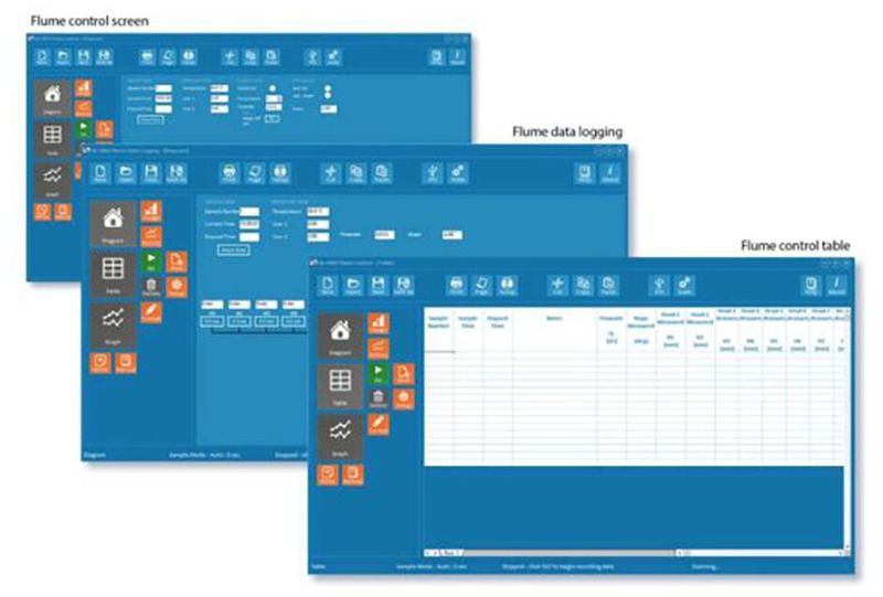
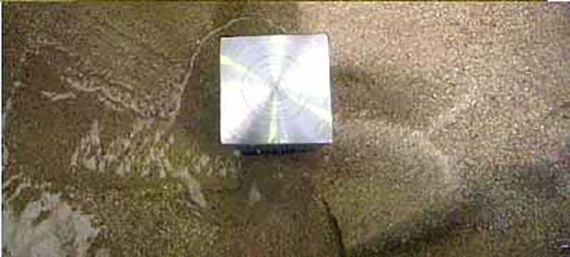
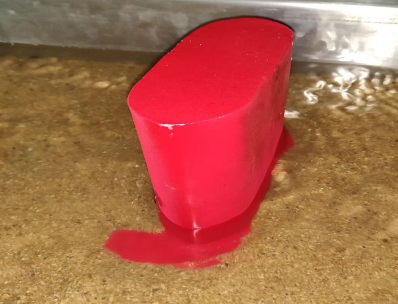
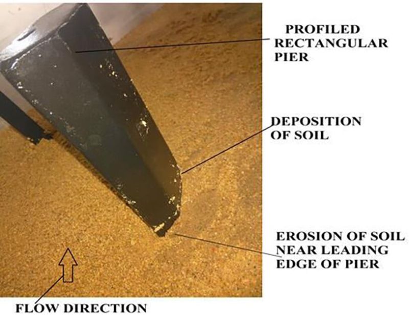
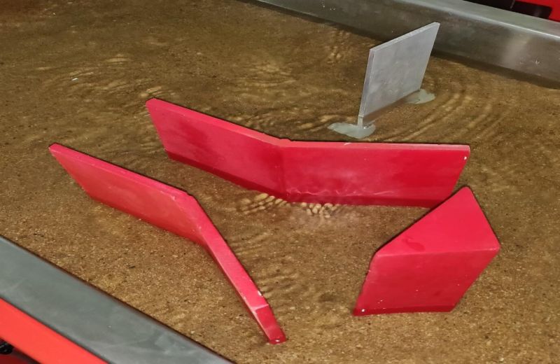
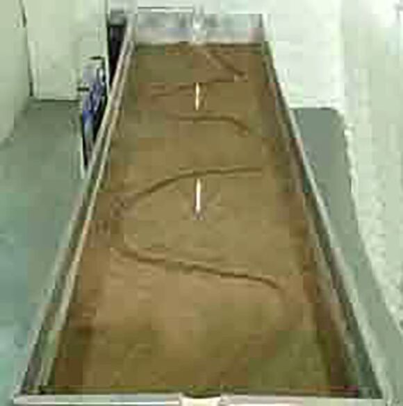
Hydrokinetic energy isthe energy generated by the movement of a body of water. The earth 's tides, waves, ocean currents and free-flowing rivers contain an untapped, powerful, highly-concentrated and clean energy resource HK systems are a class of zero-head hydropower wherebyenergy is extracted from the kinetic energy of flowing water, similar to wind turbines, rather than the potential energy of falling water. These systems can be installed in free-flowing rivers or streams. Marine energy, also known as marine and hydrokinetic energy or marine renewable energy, is a renewable power source that isharnessed from the natural movement of water, including waves, tides, and river and ocean currents. Hydrokinetic devices can beplaced directly in the stream of flowing waterand the kinetic energy of the flowing water is converted to mechanical energy that drives a generator to produce electricity. The main field of application of hydrokinetic turbines is the irrigation canals and waterways, and ocean currents. The main advantage is thatthey do not require any infrastructure like a penstock or powerhouse to create the head or to install the turbine, and they have an almost negligible environmental impact. Hydrokinetic turbine types: (a)Axial-flow turbine; (b) Cross-flow turbine. Figure 2. Axial flow turbines: (a) Non-submerged generator; (b) Submerged generators. Cross-flow turbines have been developed to overcome the problems of axial flow turbines in water. Specifications 1. Overall Flume Dimensions: 2000L x 400W x 400H in mm 2. Transparent viewing area of H x W x L = 375 x 300 x 1015 mm 3. Blade assembly: 3 Rotor blades technology 4. Electro-magnetic brake system: @ 10Kg-cm 5. Power Generation: 10W 100Watts max. 6. Computer interface & Software: Includes DAQ, SCADA software, interface & software on 11 HMI touch screen & standard in-built computer system. 7. Accessories: All required accessories & tools provided for installation and experimenting. Experimental setupThe prototypes were tested at a water velocity ranging from 0.6 to 1.1 m/s on a special setup designed for testing small scale axial hydraulic turbines [9], [10]. This closed-loop setup is provided with a transparent viewing area of H x W x L = 375 x 300 x 1015 mm, where the prototype is also located. This area is opened at the upper side, creating the conditions for free surface flow. The water velocity can be varied in the range of 0.05 1.1 m/s. All tests were performed for the maximum water depth allowed by the experimental bench in order to minimize the influence of the free surface and the turbulence at high water velocities. The hydrokinetic turbine is placed equidistant at 50 mm between the free surface and the bottom of the channel. The sustaining system presented in figure 3 is designed for an easy and safe attachment of the tested turbines. The turbine shaft is coupled to an angular adapter which transmits the horizontal motion into a vertical plane to the torque transducer and the electromagnetic particle brake, (maximum torque of 2 Nm and 0.1% accuracy of full scale), coupled to a data acquisition system. Evaluation of the water velocityThe first step carried out was to evaluate the reference mean water velocity by investigating the velocity field with a Pitot-Prandl tube. The tube is connected to a differential pressure sensor which transmits the data to a central unit for data acquisition and storage. The measured differential pressure, p, represents the dynamic pressure of the flow and is used to compute the velocity as V = 2p r , where is the water density. For each flow regime, several measurements were conducted in the middle of the channel, moving the Pitot-Prandtl tube on vertical direction, from the free surface to the bottom of the channel. The resulted values corresponding to the reference velocity of the water of 1 m/s are presented in figure. Given the measured velocity distribution, the flowra
Additional Information:
Payment Terms : T/T
Delivery Time : 24 weeks

Renewable energies are energy sources that are continuously being replenished by natural processes that occur on human timescales. In contrast, fossil fuels (coal, natural gas, oil) require millions of years of geological processes to form. Our resources of fossil and nuclear fuels (e.g. uranium) are limited. Regenerative energies, on the other hand, are virtually in exhaustible. Wind energy is a form of solar energy. Wind energy (or wind power) describes the process by which wind is used to generate electricity. Wind turbines convert the kinetic energy in the wind into mechanical power. A generator can convert mechanical power into electricity. Mechanical power can also be utilized directly for specific tasks such as pumping water. Wind power is the use of air flow through wind turbines to provide the mechanical power to turn electric generators. Wind power, as an alternative to burning fossil fuels, is plentiful, renewable, widely distributed, clean, produces no greenhouse gas emissions during operation, consumes no water, and uses little land. The net effects on the environment are far less problematic than those of nonrenewable power sources. Wind farms consist of many individual wind turbines, which are connected to the electric power transmission network. Onshore wind is an inexpensive source of electric power, competitive with or in many places cheaper than coal or gas plants. Offshore wind is steadier and stronger than on land and offshore farms have less visual impact, but construction and maintenance costs are considerably higher. Small onshore wind farms can feed some energy into the grid or provide electric power to isolated off-grid locations. Solar PV Cells energy (or Solar power) describes the process by which wind is used to generate electricity. Solar PV Cells converts the Solar energy into electrical power. DC to AC inverters are used to convert DC energy derived from PV Cells in AC energy or AC Power Supply. Solar power, as an alternative to burning fossil fuels, is plentiful, renewable, widely distributed, clean, produces no greenhouse gas emissions during operation, consumes no water, and uses little land. The net effects on the environment are far less problematic than those of non-renewable power sources. Solar farms consist of many individual PV Cells, which are connected to the electric power transmission network. Specifications for Wind Generator DC Motor Drive Control panel: - 2 pole 1 6A MCB of 230 V 50Hz. - 300V DC Voltmeter & 5A DC Ammeter - 0-200V Variable Armature Output and Fixed 200V Field Output DC Ammeter panel: - 3 Nos of 0-20A DC Ammeter DC Circuit Breaker panel: - 3 Nos of 1 16A MCB Circuit Breaker. Battery Bank Junction Panel: - 2 pole 1 16A ELCB Switch. Dump Load panel: - 0.5 /100W resistive load. Socket Panel: - 3 Nos of Screw Base Lamp Socket. - 2 Nos of 1 AC Electrical Socket. Switch Panel: - 1 Nos of 16A Cam operated rotary Horizontal Switch. - 1 Nos of 16A Cam operated rotary Vertical Switch. - 2 Nos of AC/DC switch. - 3 Nos of Stop (Toggle) Switch Bus Bar & Distribution Panel: - 12V DC bus bar - 12V DC Distribution bar Battery Charger Control Panel: - 3 Battery Charger with DC Energy Meter to measure DC parameter of Battery. 3 Phase Multifunction Meter - 1 Nos. of 3 Phase Multifunction Meter to measure AC voltage, current, power etc Energy Meter Panel: - 1 AC two wires static kWh Meter with 2 pole 1 16A ELCB Switch. Inverter Panel: - 900VA pure sine wave Inverter with AC Output Indicator. Battery Panel: - 12V, 100Ah Tubular Battery for storage. Wind Simulator: - Wind Simulator with DC Shunt Motor and 3 Al
Additional Information:
Payment Terms : T/T
Delivery Time : 16 weeks

Forces are developed when a fluid jet impinges on a stationary or moving body according to the principle of linear momentum. Several fluid flow devices utilize the forces generated by the change of momentum. For example, some hydro-electric power plants use jets of water turn Pelton turbines. Also, it is essential to design devices to withstand forces caused by the changes in momentum of fluids. Study of the effect of jet impingement on plane and curved surfaces and hence the forces generated are important for students of Fluid Mechanics and Hydraulics Engineering.
Sci-tech Impact of Jet Apparatus Model FM 01 has been designed to measure the force generated by the impingement of the jet of water on a stationary object and to demonstrate the principle of linear momentum. The apparatus can be used with the FM100 Hydraulic Bench or any other standard makes of Hydraulic Benches. The Unit can also be connected to any controlled water supply network when a drain is available. The apparatus consists of a Plexiglas cylindrical shell which houses the nozzle and the deflector and enables visualization of flow inside. A jet of water ejected from the nozzle vertically upwards impinges on a target deflector which is carried on the stem extending through the cover. The resulting force lifts the set of dead weights which gives the direct measurement of the jet impact forces. Target deflectors can be changed easily and the apparatus can be leveled. Suitable piping has been provided to drain water from the unit. Five types of target deflectors are provided. As an option, Electronic Balance with Digital Display can be supplied instead of the dead weight system for force measurement and computer compatibility.
Options
Computer based learning software is included to enable students understand and conduct experiments, tabulate results and plot graphs. The Sci-tech Impact of Jet Apparatus
Demonstration Apparatus is an important experimental set-up for any Fluid Mechanics and Hydraulics Laboratory of an educational institution
Experiments
1. Familiarization with the force measurements.
2. Demonstration of the principle of linear momentum.
3. Measurement of jet impact forces on various target deflectors.
4. Study of jet impact forces at various jet velocities.
5. Comparison of measured jet impact forces with the theory.
Measurements
1. Jet exit velocity from flow rate measurements.
2. Jet impact force from the direct measurements using dead weights or an Electronic Balance.
Important Features and Component Specifications
1. Cylindrical shell, Plexiglas, 250 mm diameter, 400 mm height.
2. Base plate with leveling screws, steel frame, and powder coated for
Corrosion resistance, 400 mm X 400 mm X 36 mm.
3. Target deflectors, 1800 hemi-spherical, 1200 Cone, 300 flat target (see option 1)
4. Nozzle, 8 mm diameter.
5. Impact surfaces:
180 hemispherical surface.
120 curve surface.
90 flat surface
6. Impact force measurement system consisting of compression spring, dead weights, weight pan and level gauge, capacity: 40N. (See option-2)
7. Set of dead weights 5, 10, 20, 50, 100, 200 and 500 grams.
8. Distance between the nozzle and target deflector: 30 mm.
Options
1. Any other type of target deflector can be supplied on request.
2. Electronics Digital Balance with Digital Display, capacity: 40N with PC based data Acquisition system for jet impact force measurements instead of dead weight system.
3. A self contained unit of Impact of Jet Apparatus with a flow controlled closed circuit water circulation unit consisting of centrifugal pump, flow meter and a sump tank can be supplied.
Additional Information:
Payment Terms : T/T
Delivery Time : 4 weeks
Weirs are generally used in rivers and other open channels to regulate and measure the flow rate.
Weirs have various cross sections and the flow rate depends on the water levels both upstream and down stream of the weir. A sharp edged notch cut out of a metal plate is a form of a weir more suitable for flow measurements. The cut outs may be of any shape, however rectangular and V-shaped notches are commonly used. Study of the flow over weirs is an important experiment for students of Hydraulics Engineering and Fluid Mechanics.
The Sci-tech Flow over Weirs & Notches Apparatus Model FM 02 has been designed to demonstrate the characteristics of flow over rectangular and V-notches and to determine the coefficient of discharge. The apparatus can be used with the FM100 Hydraulic Bench or any other standard makes of Hydraulic Benches having a channel and a provision to fix the notch for studies.
Notches are fixed to the weir carrier at the end of the channel in the Hydraulic Bench. Water is fed into the channel section and is allowed to flow over the weir. Special delivery nozzle and two stilling baffles are located in the channel of the Hydraulic Bench to provide smooth flow upstream of the weir. A vernier hook and point gauge is provided to measure the overflow height.
OPTION
Sci-Cal Computer based learning software is included to enable students understand and conduct experiments, tabulate results and plot graphs. The Sci-tech Flow over Weirs & Notches Demonstration Apparatus is an important experimental set-up for any Fluid Mechanics and Hydraulics Laboratory of an educational institution
Experiments
1. Demonstration of the flow over the rectangular notch.
2. Demonstration of the flow over the V-notch.
3. Study of discharge Vs head over the notch characteristics.
4. Determination of the co-efficient of discharge of weirs.
Measurements:
1. Overflow height or head over the notch.
2. Volumetric flow rate from measuring tank of the Hydraulic Bench.
Important Specifications
1. Wear Plates, PVC, 6 Nos., Overall size, 260mm X 160mm X 4mm. with the following
notch geometry: (a) Rectangular, width: 50mm, height: 80mm. (b) V-notch, 900 inclusiveangle, width across top: 50mm. (c) V-notch, 450 inclusive angle, width across top: 50mm. (d) V-notch, 1200 inclusive angle, width across top: 50mm. (e) Trapezoidal weir 30mm (f) Trapezoidal weir 50mm (g) Dog bone weir
2. Hook and Point Gauge, range: 0-160mm, accuracy: 0.1mm.
Options:
1. The overall dimensions of the wear plates can be modified to suit the existing Hydraulic Bench
2. Different types of notches will be supplied on request.
3. A self-contained unit of Flow over Weir Apparatus mounted on a mobile platform with a flow controlled closed circuit water circulation unit consisting of centrifugal pump, flow meter, corrosion resistant sheet metal measuring tank and a sump tank will be supplied on request.
Additional Information:
Payment Terms : T/T
Delivery Time : 4 weeks
Sci-tech Bernoullis Theorem Demonstration Apparatus Model FM 03 is an important experimental set-up for any Fluid Mechanics and Hydraulics Laboratory of an educational institutions.
The Bernoullis Theorem states that the sum of pressure head, velocity head and the potential head is constant along a streamline for a steady, in viscid and incompressible flow of fluid. The Sci-tech Bernoullis Theorem Demonstration Apparatus Model FM 03 is a bench top unit and has beendesigned to demonstrate the Bernoullis Theorem. The apparatus consists of a transparent venturi tube.Wall pressure tapings are provided along the converging and diverging portions of the venturi to measure the static pressure distribution. Pitot tubes are provided to along the centre line of the venturi. Static pressures are measured using multi-tube manometer having a manifold with an air bleed valve. Manometer can be pressurized by a hand pump. The characteristics of the flow in both convergent and divergent portions of the venturi can be studied. This apparatus can also be used to conduct laboratory experiments to (a) demonstrate the continuity equation and (b) determine the co-efficient of discharge of venturi as a flow measurement device. Water is supplied by a hose connection at the inlet and controlled by a valve at the outlet of the venturi. The complete unit is manufactured from corrosion resistant materials. The FM 100F Hydraulic Bench or any other standard hydraulic bench models can be used to supply water.
Options
Sci-Cal Computer based learning software can be offered to enable students understand and conduct experiments, tabulate results and plot graphs.
List of Experiments
Following is the list of experiments that can be carried out using the Bernoullis Theorem
Demonstration Apparatus:
1. Familiarization with static and total pressure measurements.
2. Demonstration of continuity equation.
3. Demonstration of Bernoullis theorem.
4. Measurement and display of static pressure variation along the venturi at different flow rates.
5. Investigation of static pressure, flow velocity and total pressure variation along the venturi.
6. Determination of co-efficient of discharge of the venturi.
7. Study of venturi tube as a flow measurement device.
Measurements:
1. Static pressures along the venturi.
2. Total pressures along the venturi.
3. Volume flow rate from Hydraulic Bench or direct measurements.
Specifications:
1. Venturi tube, transparent, made of clear Acrylic and having convergent and divergent portions, throat diameter: 16.0mm, maximum diameter: 26mm, upstream taper: 140, downstream taper: 210.
2. No. of static pressure taps: 7.
3. No. of Pitot tubes: 7.
4. Multi-tube manometer, 0-300 mm water column, No. of tubes: 11.
5. Optional Sci-tech Hydraulic Bench Model FM 100F
Options:
1) A self contained unit of Bernoullis Theorem Demonstration Apparatus mounted on a mobile platform with a flow controlled closed circuit water circulation unit consisting of centrifugal pump, flow meter, corrosion resistant sheet metal measuring tank and a sump tank will be supplied on request.
Optional: Sci-cal Software & Interface: Sci-tech software, interface & related sensors enable plotting of require graphs through the formulae integrated into software. The students can carry out experiments and see graphs and results in Labview.
Depending on the measurement method, the measured values can be read off the analogue manometer or digital displays. The measured values are transmitted directly to a PC via USB. The data acquisition software is included.
Additional Information:
Payment Terms : T/T
Delivery Time : 4 weeks
Orifice is a simple device used to measure fluid flow in pipes. Sci-tech Orifice Discharge Apparatus Model FM 04 has been designed to enable students to determine the co-efficient of discharge of sharp edged orifice and nozzles. It consists of a vertically mounted cylindrical transparent plastic water tank. Water is supplied from the hydraulic bench or any closed circuit controlled water supply system. The orifice is fitted in the base of the tank using special fittings flush with the inside surface. The head above the orifice is maintained constant using adjustable overflow pipe and the level is indicated by the level scale.
The flow rate through the orifice can be varied by adjusting the level of the overflow pipe suitably and hence the head over the orifice. Water emerging from the orifice is collected in the measuring tank of the hydraulic bench to make actual discharge measurements. A pitot tube with a traversing device is provided to measure the jet diameter and locate the vena contract to enable determination of contraction co-efficient. The pitot head and the total head over the orifice is measured using manometer tubes fixed adjacent to the tank. A set of four nozzles is also provided in addition to the sharp edged orifice to study the effect of geometry on the co-efficient
of discharge.
The Orifice Discharge Apparatus is designed to fit onto the platform of Sci-tech Hydraulic Bench FM100 or any other standard hydraulic bench models. Adjustable feet are provided to permit accurate leveling of the equipment before use.
The complete unit is manufactured from corrosion resistant materials.
The Orifice Discharge Apparatus is an important experimental set-up for any Fluid Mechanics and Hydraulics Laboratory of an educational institution
OPTION:
Sci-Cal Computer Based Learning Software is included to enable students understand and conduct experiments, tabulate results and plot graphs.
.
List of experiments:
1. Study of flow through orifice.
2. Investigation of water jet through orifice.
3. Locating vena contract in water jets.
4. Determination of co-efficient of velocity for orifice.
5. Determination of contraction co-efficient for orifice.
6. Determination of co-efficient of discharge for orifice.
7. Study of co-efficient of discharge of orifice at various heads over orifice.
8. Study of co-efficient of discharge of different nozzles.
9. Comparison of co-efficient of discharge of orifice and nozzles.
10. Repeat of experiments (1-7) for various nozzles.
Important Features and Specifications:
Length 13 mm, with 60 contraction and 60 diverging section
Length 13 mm, with 29 mm diameter bell-mouth approach to 60 diverging section, Length 60 mm, with 29 mm diameter bell-mouth approach to 51 mm long parallel section, Length 60 mm, with 29 mm diameter bell-mouth approach, to 30 diverging section and 25 mm long parallel section
Triangular orifice dimensions: Each side nominally 12.1 mm, including 1.5 mm corner radius
Square orifice dimensions: 9 mm square
3. Orifice material: Aluminum
Optional Computer based learning software is included to enable students
Options:
1. A self contained unit of Orifice Discharge Apparatus mounted on a mobile platform with a flow controlled closed circuit water circulation unit consisting of centrifugal pump, flow meter, corrosion resistant sheet metal measuring tank and a sump tank will be supplied on request.
2. Orifices and Nozzles of different geometries will be supplied on request.
Additional Information:
Payment Terms : T/T
Delivery Time : 4 weeks

Study of pressure losses in bends and fittings in any pipe system is useful in view of the loss of head and consequent pumping power requirements. Sci-tech Pressure Loss in Bends and Fittings Apparatus Model FM05 is important equipment for any Fluid Mechanics and Hydraulics Engineering Laboratory of an educational institution. The Pressure Loss in Bends and Fittings apparatus has been designed to enable students to measure pressure losses across various types of bends and fittings in a typical pipe system.
The apparatus, including the instrumentation for pressure measurements, is mounted in a robust vertical frame work mounted on wheels. The study devices include bends of small and large radius, 450 mitre bend, 900 elbow, sudden enlargement and contraction and a gate valve. All these devices are equipped with pressure tapings both in the upstream and the downstream to measure the pressure drop. Pressure tapings across bends and fittings are connected to a multi-tube water manometer mounted on the frame work.
A hand pump with a non-return valve is used to pressurize manometers. Pressure tapings across the gate valve is connected to the Bourdon tube pressure gauge. Another gate valve is provided at the downstream of the apparatus to vary the water flow rate through the devices. The FM 100 Hydraulic Bench or any other standard hydraulic bench models can be used to supply water.
OPTION:
Computer Based Learning Software is included to enable students understand and conduct experiments, tabulate results and plot graphs. The Pressure Losses in Bends & Fittings, is an important experimental set-up for any Fluid Mechanics and Hydraulics Laboratory of an educational institution.
List of experiments:
1. Measurement of pressure losses across different kinds of bends, fittings and gate valve at various water flow rates.
2. Calculation of pressure loss co-efficient at various flow rates and comparison with the data available in the literature.
3. Comparison of pressure loss co-efficient for different bends.
4. Determination of pressure drop Vs flow characteristic curve for different openings of the gate valve.
Important Features and Specifications:
1. Nominal pipe diameter: 25mm.
2. Pipe, bends and fittings made of Plastic.
3. Manometer, Range: 0-500mm WC, No. of tubes: 14, differential manometers: 7.
4. Enlargement diameter: 24mm.
5. Contraction diameter: 13.5mm.
6. Study devices : Short bend, large bend, 450 mitre bend, 900 elbow, enlargement, contraction, gate valve.
Options:
1. A self contained unit of Pressure Loss in Bends and Fittings apparatus mounted on a mobile platform and with a flow controlled closed circuit water circulation unit consisting of centrifugal pump, flow meter, corrosion resistant sheet metal measuring tank and a sump tank will be supplied on request.
2. Other types of bends, fittings and valves for studies can be incorporated on request.
Additional Information:
Payment Terms : T/T
Delivery Time : 4 weeks
Analysis of any fluid flow problem depends upon the laminar, transitional or turbulent nature of the fluid flow. Visualization and understanding and of the laminar, transitional and turbulent nature of flows is important for students of fluid mechanics, hydraulics and related areas in science and technology.
Sci-tech Osborne Reynolds Demonstration Apparatus Model FM 06 is a bench top flow visualization unit and has been designed to demonstrate the laminar, transitional and turbulent flows. The apparatus consists of a vertical flow visualization glass pipe with a bell mouth entry through which water flows with minimum flow disturbances. The laminar, transitional and turbulent flows can be obtained by varying the water flow rate using the membrane type flow control valve fixed at the exit of the flow visualization pipe. Water flow rate and hence the flow velocity is measured by the volumetric measuring tank (of the hydraulic bench). Water is supplied to the flow visualization pipe from the supply tank at a constant head. The supply tank consists of glass beads to reduce flow disturbances. Flow patterns are visualized using dye injection through a needle valve. The dye injection rate can be controlled and adjusted to improve the quality of flow patterns. The complete unit is manufactured from corrosion resistant materials. Sci-tech FM 100 Hydraulic Bench or any other standard hydraulic bench models can be used to supply water.
Important Features and Specifications:
1. Flow visualization pipe, glass, 10mm internal diameter, 700mm long with membrane type flow control valve at exit.
2. Supply tank, 4 liters capacity, with glass beads for flow improvement and bell mouth at the exit.
3. Dye reservoir and injector, 0.45 liter capacity, with needle valve at exit.
4. Optional Heater Module on a separate free-standing unit. Heater Module connects to the water supply line to heat the water, varying its temperature and viscosity. Heater Controls vary the electrical heat input and the flow rate, to give steady conditions over a range of temperatures
Options:
A) Interactive Computer Aided Instruction Software System
B) Horizontal type Osborne Reynolds Demonstration Apparatus available, Model FM 06H
C) A self-contained unit of Osborne Reynolds Demonstration Apparatus mounted on a mobile platform with a flow controlled closed circuit water circulation unit consisting of centrifugal pump, flow meter, corrosion resistant sheet metal measuring tank and a sump tank will be supplied on request.
List of Experiments:
1. Dye flow visualization of laminar, transitional and turbulent flows.
2. Study of change of flow pattern from laminar to turbulent type as a function of Reynolds number.
3. Calculation of critical velocities and critical Reynolds numbers.
4. Study of pipe flows and related Reynolds number correlations.
5. Correlation of Reynolds number and the nature of flow and comparison with the data available in the literature.
6. Investigation of the effect of varying viscosity and demonstration that the Reynolds number at transition is independent of viscosity
Additional Information:
Payment Terms : T/T
Delivery Time : 4 weeks


Study of pressure loss in pipes is important in view of the loss of head due to friction and consequent pumping power requirements in any pipe system. Sci-tech Pressure Loss in a Pipe Apparatus Model FM 07 is an experimental set-up necessary for any Fluid Mechanics and Hydraulics Laboratory of an educational institution.
Sci-tech Pressure Loss in a Pipe Apparatus Model FM 07 has been designed to enable students to measure loss of head due to friction in a pipe and to study the effect of change in flow velocity. Laminar and turbulent flow regimes can be obtained by varying the flow velocity and hence the flow Reynolds number. The apparatus consists of a horizontal test pipe with static pressure tapings at the upstream and downstream ends to measure head loss due to friction. Extra pipe lengths are provided at the inlet and exit to allow the flow to become fully developed and to damp out the flow disturbance originating from the valves and fittings. The test pipe is mounted on a support frame and there is a provision for levelling. Water is supplied from the hydraulic bench (for higher flow rates) and the constant head feeding tank (for lower flow rates).
Pressure drop along the test pipe length is measured using the U-tube mercury manometer or the pressurized water manometer depending upon the flow velocity. These manometers are mounted with calibrated scales. The flow rate and hence the velocity though the test pipe is controlled by a regulation valve at the exit and the flow rate is measured by the flow meter or the measuring tank of the hydraulic bench. Experiments can be conducted at various flow velocities or Reynolds numbers to obtain pressure loss in laminar or turbulent flow regimes. The complete unit is manufactured from corrosion resistant materials. Sci-tech Hydraulic Bench Model FM 100 or any other standard hydraulic bench models can be used to supply water.
OPTION:Sci-Cal Computer Control Software & Interface in LabVIEW
.
Experiments Possibilities
1. Study of loss of head due to friction in a circular pipe at various mean flow velocities.
2. Study of friction factors in laminar and turbulent flow regimes.
3. Demonstration of the law of resistance in laminar to turbulent flow regimes.
4. Establishment of critical Reynolds number.
5. Comparison of experimental results with the well known Moodys diagram.
Specifications:
1. Test pipe, SS 304 3mm bore, 650mm long with two static pressure taps at 500mm apart.
2. Feeding tank, capacity: 10 litres, constant water head: 900mm.
3. U-tube manometer, range: 500mm.
4. Pressurized water manometer, range: 500mm.
5. Flow meter, range: 2 LPM.
6. Ancillaries include measuring cylinder (1 litre capacity), hand pump and a sample of test pipe (100mm long).
Options
1. A self contained unit of the Pressure Loss in a Pipe Apparatus mounted on a mobile platform and with a flow controlled closed circuit water circulation unit consisting of centrifugal pump, flow meter, corrosion resistant sheet metal measuring tank and a sump tank will be supplied on request.
2. A digital pressure meter can be supplied as an alternative to the mercury U-tube manometer on request.
3. Sci-Cal Computer Control Software & Interface in LabVIEW.
Additional Information:
Payment Terms : T/T
Delivery Time : 4 weeks


Study of net force due to pressure on a submerged surface and the concept of center of pressure are of importance in fluid mechanics and hydraulics engineering. This understanding is important for the design of several structures and hydraulic equipment such as dams, ship building, maritime structures and other underwater bodies. The Sci-tech Hydrostatic Force & Center of Pressure Apparatus Model FM 08 demonstrates various principles of hydrostatics and is an important experimental set-up necessary for any Fluid Mechanics and Hydraulics Laboratory of an educational institution.
The Sci-tech Hydrostatic Force & Center of Pressure apparatus Model FM 08 has been designed to enable students measure the net hydrostatic force and the center of pressure on a submerged plane surface. The apparatus consists of a quadrant fixed to the balance arm. The balance arm is pivoted at the knife edge on the centerline of the quadrant. The quadrant is immersed in the Perspex water tank having an integral flat base.
The base of the water tank has levelling screws for accurate leveling. The balance arm is placed above the water tank and the quadrant is balanced by the adjustable counter- balance such that the rectangular end face of the quadrant is always vertical.
When the quadrant is submerged in water, the arrangement is such that only the forces acting on the rectangular end face produces a moment around the knife edge axis. The system of beam level indicator, balance pan and the adjustable counterbalance on the balance arm provide the necessary arrangement for the measurement of the resultant hydrostatic force and the center of pressure on the rectangular end face of the quadrant.
Water can be poured into the tank and may be drained through the drain cock at the base of the tank. Water level scale is provided on the side face of the quadrant. Experiments can be carried out for both partially and fully submerged cases by varying the water level in the tank. The FM100 Hydraulic Bench or any other standard hydraulic bench models can be used to supply water
The Sci-tech Hydrostatic Force & Center of Pressure apparatus is an important experimental set-up for any Fluid Mechanics and Hydraulics Laboratory of an educational institution
OPTION:
Sci-Cal Computer Based Learning Software is included to enable students understand and conduct experiments, tabulate results and plot graphs.
List of Experiments:
1. Measurement of hydrostatic force on a fully and partially submerged vertical plane surface.
2. Determination of center of pressure on a fully and partially submerged vertical plane surface.
3. Comparison of experimental results with principles of hydrostatics.
Specifications:
1. Water tank, Perspex, Internal Size: 350Lmmx350Dmmx180mmW; Capacity: 20 liters with level adjustment support screws at the base.
2. Quadrant, 120mm internal radius, 200mm outer radius, 75mm width.
3. Balance arm.
4. Balance pan.
5. Beam level indicator.
6. Adjustable counter-balance.
7. Distance between balance pan and knife edge: 285mm.
8. Set of standard weights: 4 x 100gr; 1 x 50gr; 5 x 10gr; 1 x 5gr
9. Two Spirit levels.
10. Optional, Computer based DAQ learning software.
Additional Information:
Payment Terms : T/T
Delivery Time : 4 weeks

Sci-tech Metacentric Height Apparatus Model FM 08A demonstrates the metacentric height of a floating body and the height variation is used with Hydraulic Bench Model MH100 or a separately supplied bowl. The equipment consists of a rectangular pontoon. The centre of gravilty of the pontoon can be moved sideways by moving horizontal jockey weight. The angle of the tilt of the pontoon is indicated by a plumb bob on a scale attached. The centre of gravity of the pontoon can also be moved vertically by means of adjustable vertical weights on the mast.
Specifications
Open Tank: Made of Acrylic, for water storage. Size: 380 mm X 480 mm x 300 mm (W X B X H)
Floating Body: Made of non-corrosive transparent Acrylic material, used as floating body (Ship). Plumb, protector, weights & counter weights and mounted on this ship
Size of Floating Body: 300 mm X 300 mm x 270 mm (W X B X H)
Horizontal scale graduation: 1mm
Mast Height: 400mm with 1mm graduation
Counter Weights: Mounted on floating body, made of non-corrosive aluminum material, for making ship horizontal of floating body.
Protector: To determine the angle of tilt of ship from its axis, protractor is attached on the ship.
Plumb: Made of Stainless Steel, fitted at center of protector for vertical downward line.
Jockey weight: Made of Aluminum & copper, to provide imbalance of system. Two set of pan, each of 50 g and a set of 8 discs each weighing 50 g is supplied.
Experiment Possibilities
Determination of Metacentric Height.
Additional Information:
Payment Terms : T/T
Delivery Time : 4 weeks

Sci-tech Flow Channel Apparatus Model FM 09 is useful to carryout some basic experiments in fluid mechanics related to open channel flows and visualization of flow patterns around immersed bodies.
The Sci-tech Flow Channel Apparatus is required to demonstrate basic principles of fluid mechanics and is important equipment for any Fluid Mechanics and Hydraulics Laboratory of an educational institution.
The apparatus consists of a clear acrylic plastic open flow channel test section for flow visualization. The channel has a rectangular cross section of large depth-to-width ratio to facilitate conducting variety of experiments. Undershoot and overshoot adjustable weirs are provided at the inlet and exit ends of the channel to control the depth of flow and flow velocity. Water is supplied through a stilling tank and nozzle to ensure clean flow at the inlet of the flow channel with minimum flow disturbances. The discharge from the channel is collected in the volumetric measuring tank of the hydraulic bench and is used to determine the average flow velocity. The dye injection system consisting of a dye reservoir, flow control valve and dye injection needles are supplied to inject dye into the flow stream for the visualization of stream line patterns.
Broad and sharp crested weirs and models of various bodies such as aerofoil, cylinder and ship are supplied with the apparatus to enable several open channel flow experiments and flow visualization experiments. The apparatus has adjustable feet for leveling. The FM00 Hydraulic Bench or any other standard hydraulic bench models can be used to supply water.
OPTION:
Computer based learning software is included to enable students understand and conduct experiments, tabulate results and plot graphs. Flow Channels of larger dimensions and having different features such as tilting floor and advanced instrumentation systems required for research and education can be supplied on request by the user. The Sci-tech Flow Channel Apparatus Model FM 09is an important experimental set-up for any Fluid Mechanics and Hydraulics Laboratory of an educational institution
Experiments
1. Study of basic open channel flows with variable depth of flow.
2. Calculation of Froude number and similarity of flows.
3. Study of uniform flow, gradually varied flow and rapidly
varied flow and Froude number correlations.
4. Study of flow over different types of weirs undershoot and
over shoot weirs, broad and sharp crested weirs.
5. Study of flow under a sluice gate.
6. Visualization of streamline patterns around aerofoil, cylinder, ship model, hump etc.
7. Optional: Determination of Chezys And Mannings Coefficient For Different Aggregate Bed Using Different Notches In Hydraulic Bench
Specifications
1. Open flow channel made of clear acrylic plastic,
20mm width, 160mm depth, and 625mm length.
2. Dye reservoir, capacity: 0.5 liters
3. Dye injection needles, 5 Nos.
4. Models, 8 Nos. (a) broad crested weir (b) sharp crested weir (c) symmetrical aerofoil
(d) non-symmetrical aerofoil (e) cylinder, 15mm diameter (f) cylinder, 30mm diameter
(g) ship model and (h) hump
5. Spirit level.
Optional: 1. Computer based learning software.
2. A self contained unit of Flow Channel Apparatus mounted on a mobile platform with a flow controlled closed circuit water circulation unit consisting of centrifugal pump, flow meter, corrosion resistant sheet metal measuring tank and a sump tank will be supplied on request.
2. Depth gauge to measure depth of flow in the flow channel can be supplied on request.
3. Different models as per the requirement of the user can be supplied on request.
Additional Information:
Payment Terms : T/T
Delivery Time : 4 weeks

Pressure measurement is important in any branch of Science and Engineering. Bourdon tube pressure gauges are extensively used in industry. Proper calibration of these gauges is essential to make accurate pressure measurements. Calibration using dead weights is a direct method commonly used for industrial Bourdon tube pressure gauges. Sci-tech Dead Weight Pressure Gauge Calibrator Model FM 10 is important equipment necessary for any Fluid Mechanics and Hydraulics Laboratory of an educational institution.
Sci-tech Dead Weight Pressure Gauge Calibrator Model FM 10 is a bench top dead weight pressure gauge calibrator consists of a precision machined piston and cylinder assembly mounted on levelling screws. A Bourdon gauge is supplied for calibration. The weights supplied are added to the upper end of the piston rod which is rotated to minimize friction effects. The gauge is thus subject to known pressures which may be compared with the gauge readings and an error curve drawn. Detailed Operation & Maintenance Manual is provided along with the trainer.
Sci-tech Pressure Gauge Calibrator FM 10 has been designed to demonstrate the principle of calibration using dead weights and enable students calibrate a Bourdon tube pressure gauge of interest to the education and industry. It consists of a vertically mounted precision machined leak proof piston and cylinder assembly mounted on a base with leveling screws. The piston rod has an extension and a platform to place weights during calibration. A set of weights and a Bourdon tube pressure gauge are supplied with the apparatus.
The cylinder is connected to the gauge through a system of leak proof valves and flexible tubing. A non-return valve is fitted at the water supply side of the cylinder. Blanking pug is provided to drain water from the apparatus. The gauge can be subjected to known pressures by placing different weights on the piston. Applied pressures can be calculated and the values compared with the readings obtained indicated on the pressure gauge scale. The Pressure Gauge Calibrator can also be used to calibrate other Bourdon type pressure gauges with proper tubing connections.
Water can be supplied from the FM100 Hydraulic Bench or any other source.
Optionally, unit allows pressure gauges to be accurately calibrated up to 300 bar, with an accuracy of 0.015%.
OPTION:
Computer based learning software can be included to enable students understand and conduct experiments, tabulate results and plot graphs. All components are manufactured from corrosion resistant material.
The Pressure Gauge Calibratoris an important experimental set-up for any Fluid Mechanics and Hydraulics Laboratory of an educational institution.
Technical Specifications
Experiment Capabilities
Study concepts of pressure = Force/Area and pressure scales
Calibration and the use of a Dead-weight Pressure Calibrator
Additional Information:
Payment Terms : T/T
Delivery Time : 6 weeks

Study of conditions necessary for the stable equilibrium of floating bodies is important for the design of floating bodies such as ships, rafts and pontoons. In order to familiarize students with the laws of floatation, it is essential to demonstrate the various principles of hydrostatics including the importance of relative positions of the center of buoyancy and the center of gravity and the metacentric height of the floating body.
The Sci-tech Stability of a Floating Body Apparatus Model FM 11 is a bench top unit designed to demonstrate the conditions for the stable, unstable and neutral equilibrium. The position of metacenter and hence the metacentric height can be varied by changing the weight distribution to obtain stable or unstable equilibrium conditions. The apparatus consists of a rectangular plastic pontoon. The center of gravity of the pontoon can be varied by changing the position of the adjustable sliding weight on a vertical mast.
Various degrees of heel can be obtained by sliding a weight along a lateral slide rod. Thus different stability conditions can be obtained be varying the positions of weights on the vertical and lateral slides. The angle of heel can be read using a plumb bob and the scale marked on the lateral slide. The Sci-tech Stability of a Floating Body Apparatus Model FM 11 is important equipment for the marine, navel architecture, civil, hydraulic and mechanical engineering laboratories of educational institutions.
The complete unit is manufactured from corrosion resistant material. The experiments can be conducted by filling the volumetric tank of the FM100 Hydraulic Bench or any other available standard hydraulic bench models.
OPTION:
Sci-Cal Computer based learning software is included to enable students understand and conduct experiments, tabulate results and plot graphs. The Sci-tech Stability of a Floating Body Apparatus is an important experimental set-up for any Fluid Mechanics and Hydraulics Laboratory of an educational institution.
List of experiments:
1. Familiarization with the laws of floatation and principle of working of floating bodies.
2. Determination of center of gravity of a pontoon.
3. Determination of center of buoyancy of a pontoon.
4. Determination of angle of heel of a pontoon.
5. Determination of metacenter and metacentric height of a pontoon.
6. Study of stable, unstable and neutral equilibrium conditions
of a pontoon by varying metacentric height.
7. Comparison of experimental results with theoretical calculations.
Specifications:
1. Pontoon, rectangular, plastic, length : 325mm, width : 200mm, overall height : 450mm.
2. Angle of heel scale : +/- 300.
3. Vertical sliding weight : 0.6Kg.
4. Lateral sliding weight : 0.2Kg.
5. Vertical mast height : 400mm with scale.
6. Lateral slide rod with scale.
Options:
1. Other types of floating bodies to meet specific requirements of users (for example a ship model) can be supplied on request.
2. A plastic basin of 50 liter capacity can be supplied on request. This is required in cases where volumetric tank of the hydraulic bench is not available for conducting experiments.
1. Sci-Cal Computer based learning software is included to enable students understand and conduct experiments, tabulate results and plot graphs.
Additional Information:
Payment Terms : T/T
Delivery Time : 4 weeks
Pumps are connected in series and parallel to obtain the required flow rate and head in several applications including domestic, industrial, irrigation and drainage. Energy is supplied to the pumps by electric motors and the potential energy of the liquid is increased by the action of the impeller rotating inside a volute casing. It is essential for students to understand the operation and performance characteristics of centrifugal pumps operating in both series and parallel connection. The is an experimental set-up necessary for any Fluid Mechanics and Hydraulics Laboratory of an educational institution. The Sci-tech Series & Parallel Pump Test Apparatus Model FM 12 has been designed to enable students to study the operation and performance characteristics of typical centrifugal pumps connected by flexible tubing and valves to operate in both series and parallel mode. The apparatus can also be used to conduct experiments on a single centrifugal pump independently. The apparatus consists of two similar variable speed centrifugal pumps having independent discharge manifold connected by plastic tubing with connectors to enable quick change of operation to series or parallel modes. Shut-off valves in the pipe system enable the pumps to be connected in series or in parallel. Pumps are driven by a AC motors of adjustable speed. Motors are suspended and the driving torque is measured using torque wrench. Motor speeds and power consumption are digitally displayed on the control panel. The apparatus can be connected to the Sci-tech FM 100 Hydraulic Bench or any other hydraulic bench models to supply and re-circulate water. Bourdon tube pressure gauges are mounted at the inlet and exit of the pumps to measure increase of head across the pumps. The independent discharge manifolds have pressure gauges and flow control valves upstream of the discharge pipe and the diffuser. The flow rate through the pump system is measured using the measuring tank of the hydraulic bench and can be checked independently by water flow meters fixed at the delivery side of both pumps. The Sci-tech Series & Parallel Pump Test Apparatus is a compact unit and all components and instrumentation are placed in a robust and mobile frame. OPTIONS: Sci-Cal Computer based learning software is included to enable students understand and conduct experiments, tabulate results and plot graphs. The Sci-tech Series & Parallel Pump Test Apparatus is an important experimental set-up for any Fluid Mechanics and Hydraulics Laboratory of an educational institution. The manual describing the theoretical and practical aspects of the apparatus, operation and maintenance, analysis of results and sample of results will be supplied with the equipment. List of Experiments Series or Parallel Centrifugal Pump Operation: 1. Study of operation and working of centrifugal pumps connected in series and parallel. 2. Study of matching of pumps, starting and stopping of pumps in series and parallel connection. 3. Determination of power requirement for series and parallel operation. 4. Determination of hydraulic power output in series and parallel operation. 5. Investigation of performance and characteristics in series and parallel operation. * Effect of pump speeds pumps to be operated at same and different speeds. * Head, discharge, speed, power and efficiency curves. Single Centrifugal Pump Operation: 1. Study of the operation and working of centrifugal pump. 2. Determination of power requirement of the pump. 3. Determination of the hydraulic power output of the pump. 4. Investigation of the performance and characteristics of centrifugal pump: * The effect of pump speed. * Head, discharge, speed, power and efficiency curves. * Non-dimensional performance curves. * Determination of specific speed. * Determination of net positive suction head. Important Features and Specifications: 1. Pumps: 2 Nos, centrifugal type, max. head: 21 m water, max. Flow rate: 90 Lpm. 2. Motors: 2 Nos, AC
Additional Information:
Payment Terms : T/T
Delivery Time : 8 weeks
Centrifugal pumps are widely used for pumping liquids in several applications including domestic, industrial, irrigation and drainage. Energy is supplied to the pump by an electric motor and the potential energy of the liquid is increased by the action of the impeller rotating inside a volute casing. It is essential for students to understand the operation and performance characteristics of centrifugal pumps. The Sci-tech Centrifugal Pump Test Apparatus Model FM 13 is an experimental set-up necessary for any Fluid Mechanics and Hydraulics Laboratory of an educational institution.
The Sci-tech Centrifugal Pump Test Apparatus Model FM 13 has been designed to enable students to study the operation and performance characteristics of a typical centrifugal pump. The module consists of a variable speed centrifugal pump assembly having an independent discharge manifold interconnected by plastic tubing with quick release connectors. The pump is driven by a AC motor of adjustable speed. The motor is suspended and the driving torque is determined with a torque wrench. The motor speed and power consumption are digitally displayed on the control panel. The pump can be connected to the Sci-tech Hydraulic Bench FM 100 or any other hydraulic bench models to supply and re-circulate water. Bourdon tube pressure gauges are mounted at the inlet and exit of the pump to measure increase of head across the pump. The independent discharge manifold has a pressure gauge and a flow control valve upstream of the discharge pipe and the diffuser. The flow rate through the system is measured using the measuring tank of the hydraulic bench and can be checked independently by the water flow meter fixed in the discharge.
The Sci-tech Centrifugal Pump Test Apparatus is a compact unit and all components and instrumentation are placed in a robust and mobile frame.
List of Experiments:
1. Study of the operation and working of centrifugal pump.
2. Determination of power requirement of the pump.
3. Determination of the hydraulic power output of the pump.
4. Investigation of the performance and characteristics of centrifugal pump :
The effect of pump speed.
Head, discharge, speed, power and efficiency curves.
Non-dimensional performance curves.
Determination of specific speed.
Determination of net positive suction head.
Important Features and Specifications:
Important Features and Specifications:
1. Centrifugal pump size- 25.4 mm x 25.4 mm (Approx), Discharge: 15-30 lpm at 30 meter (Approx), Total head: 12 meter (Approx).
2. Driving Motor: HP, AC electric motor
3. Power Measurement
4. RPM Indicator with sensor, Range - 0 to 9999
5. Pressure Gauges: 5 Kg/ Sq. cm.
6. Vacuum Gauge: 760mm (approx)
7. Foot Valve: size: 1 (approx) Plastic
8. Energy meter
9. Stand: M.S. Structure with powder coating or Alumium profile structure.
Additional in case Hydraulic Bench not used:
10. Measuring Tank: 40 Liter non Corrosive PVC/Acrylic tank
11. Mechanical level measurement facility with scale.
12. Sump Tank: 100 Liter non Corrosive PVC/FRP tank
13. Stop Watch.
14. Piping & fittings & valves.
15. Flow measurement facility.
Measurements:
Power input to the motor.
Torque and power input to pump.
Pump rotational speed.
Pump suction and delivery pressures.
Flow rate.
Options:
1) Sci-Cal Computer based learning software is included to enable students understand and conduct experiments, tabulate results and plot graphs. The Sci-tech Centrifugal Pump Test Apparatus is an important experimental set-up for any Fluid Mechanics and Hydraulics Laboratory of an educational institution.
Additional Information:
Payment Terms : T/T
Delivery Time : 8 weeks

The concept of vortex flows is important in many engineering applications of fluid mechanics. The flow circulates about a fixed center and the stream lines are concentric circles. The classification of vortex flows depends upon the functional relationship between the flow velocity and radius. In the free vortex, the flow velocity is inversely proportional to the radius and the total head in the flow field remains constant. In the forced vortex, the whole body of the fluid rotates as if it is a solid and the flow velocity is directly proportional to the radius. It is essential to demonstrate free and forced vortex flows to understand the basic concepts of fluid mechanics. The Sci-tech Free and Forced Vortices Apparatus Model FM 14is an important experimental set-up necessary for any fluid mechanics and physics laboratories of an educational institution.
The Sci-tech Free and Forced Vortices Apparatus Model FM 14 has been designed to generate free and forced vortices. It is possible to measure surface profiles and total head distributions in the vortex flow field. The apparatus consists of a transparent cylindrical tank having a hole in the center of the base to fix interchangeable push-in orifices while conducting free vortex experiments. The cylinder is mounted on a base plate having leveling screws. The free vortex is generated by discharging water from the tank through the orifice in the base. Two 12mm diameter flow entry tubes placed diametrically opposite near the wall at the base and angled at about 200 to the diameter supply water imparting swirling motion to the liquid entering the vessel. Forced vortex experiments are conducted by closing the orifice at the base by a bushed plug. The forced vortex is generated in the tank by rotating the two bladed paddle positioned at the base.
The paddle rotates on a vertical shaft which is supported by the bushed plug at the base and a suitable hole in the bridge piece fitted across the diameter of the tank at the top. Water jets from the two 8mm diameter flow entry tubes placed diametrically opposite and angled at about 700 to the diameter impinge on the blades and rotate the paddle. Water is drained using the 12mm diameter tubes. The bridge piece accommodates depth gauges required to map the vortex profiles. The total head in the free and forced vortex flow field is measured using a pitot probe. Colored dye can be injected into the flow using hypodermic tubes to visualize streamlines. The FM00 Hydraulic bench or any other standard hydraulic bench models can be used to supply water. A constant head overhead tank can also be used to supply water at controlled flow rate. The complete unit is manufactured from corrosion resistant material.
specifications
1. Cylindrical tank, clear acrylic, diameter: 275mm, height; 275mm mounted on base plate with leveling screws, complete with pipe work, valve fittings and connections.
2. Height of overflow point: 200mm.
3. Orifice diameters: 8, 16 and 24mm.
4. Depth gauges at 0, 20, 40, 60, 80, 100 and 110mm from center.
5. Pitot probes, 0.9mm OD, nose at 15, 25, 35 and 45mm from center.
6. Flow inlet tubes, 8 and 12 mm diameter.
7. Paddle, two bladed, 240mm overall diameter.
8. Bridge piece with scale.
9. Hypodermic tube for dye injection with dye tank and flow control valve.
10. Water manometer.
11. Bushed plug.
12. Hydraulic Bench (Not offered as part of the trainer)
Experiments
1. Demonstration of free and forced vortices.
2. Determination of surface profile of a free vortex.
3. Determination of total head variation in free vortex.
4. Dye flow visualization of stream lines in free vortex.
5. Determination of surface profile of a forced vortex.
6. Determination of total head variation in forced vortex.
7. Dye flow visualization of stream lines in forced vortex.
8. Comparison of results with theoretical predictions.
Additional Information:
Payment Terms : T/T
Delivery Time : 8 weeks
Sci-tech Hydraulic Ram Pump Demonstrator Model FM 15 uses water hammer effect to pump water. It is a simple hydraulic machine which uses the kinetic energy of a large quantity of falling water from the source to lift a smaller quantity of water to a higher elevation. It can be used for example, to lift water from a stream, pond or a spring to a storage tank. This device is useful where small quantities of water are required to be pumped from the nearby source for the purposes such as house hold, gardening, or live stock when power supplies are limited. A hydraulic ram pump can be used where the usable fall from the water source to the pump is at least one meter. The hydraulic ram pump demonstrator is important equipment for civil, mechanical, agricultural and related branches of engineering educational institutions.
The hydraulic ram pump demonstrator has been designed to familiarize students with water hammer effect and the principle of operation of hydraulic ram pump. The pump can be mounted on and connected to the Sci-tech FM100 Hydraulic Bench or any other hydraulic bench. The unit consists of a header tank connected to the hydraulic bench to supply water and the delivery section connected to a delivery tank at a higher elevation. The pump comprises of the piping system with inlet and outlet connections and a valve block mounted with the air vessel to reduce hydraulic shock. The supply line consists of inner and outer valves which operate in a cycle during the working of the pump. Different weights may be applied on the outer valve platform to change closing pressure and hence the pump cycle time. Pressure gauge is provided to measure pressure fluctuations.
The Hydraulic ram pump demonstrator is a compact unit and all components and instrumentation are placed in a robust and mobile frame. The complete unit is manufactured from corrosion resistant material.
Important Features and Specifications:
1. Header tank, supply head: 0.25 0.75 m variable.
2. Delivery tank, delivery head: 0.75 1.5 m variable.
3. Pump capacity: 2 lpm.
4. Inner valve.
5. Air vessel.
6. Pressure gauge, digital readout.
7. Outer valve with weight platform.
8. Piping system.
9. Mobile frame and panel.
Optional:Sci-Cal Computer Control Software & Interface
Experiments:
1. Demonstration of the water hammer effect.
2. Familiarization with the operation of hydraulic ram pump.
3. Study of pressure versus flow characteristics of hydraulic ram pump.
4. Determination of efficiency of hydraulic ram pump.
5. Study of the effect of different weights on outer valve on hydraulic ram pump performance.
Additional Information:
Payment Terms : T/T
Delivery Time : 8 weeks
Sci-tech Pelton Wheel Turbine Demonstrator Model FM 16 is an impulse transferred by the impact of water jet on the runner fitted with buckets. The change in the momentum of water jet results in the force on the buckets which turns the runner. The torque developed is converted into useful work. Pelton turbines are used in hydro-electric power plants operating with water source available at high heads and low volume flow rates. It is essential for students to understand the characteristics of Pelton turbines. The Sci-tech Demonstration Unit is necessary equipment machinery for fluid mechanics educational institutions. Pelton turbine turbine and energy and its operations and performance Pelton Turbine for hydraulics laboratory is very important part of syllabus of fluid mechanics in educational institutions.
The Sci-tech Pelton Wheel Turbine Demonstrator Model FM 16 has been designed to enable students to study the operation and characteristics of a typical Pelton turbine. The unit has to be connected to the Sci-tech Hydraulic Bench FM 100. The runner is mounted on a horizontal shaft and is fitted with buckets. A horizontal jet of water issuing from the nozzle produces a force on the bucket. The flow rate through the nozzle can be adjusted by varying the position of the needle valve inside the nozzle. The output of the turbine is measured using a brake band friction dynamometer. Digital RPM indicator with proximity sensor is provided to measure shaft speed. The runner and nozzle assembly is enclosed in a casing. The bottom of the casing is open and allows water leaving the buckets to drain. The front face of the casing is made transparent using Perspex to allow observation of turbine during operation. The unit is a compact and designed for quick and easy setting up of experiments. All components and instrumentation are placed in robust and mobile frame.
Specifications
PELTON WHEEL TURBINE
a) Rating: 50W
Number of buckets: 16
Brake:
Water pump, computer controlled:
Pressure sensor: 0 to 100 PSI (0 to 6.7 bar).
Load cell - force sensor: 0 - 50N.
Flow sensor: 2 to 150 l/min.
Speed sensor: 0 - 20000 rpm.
Water transparent tank, capacity: 130 l approx.
b) Flow measuring Unit: A 50 mm (2) Venturi meter/Orifice meter with double column differential manometer (Without Mercury) on a panel board to measure the difference of pressure.
c) Reservoir of size 0.5 m length x 0.5 m width x 0.5 m. height with drain valve of size & a bend.
d) Starter, Switch, Digital speed indicator, Pipe line with gate valve & foot valve etc.
Optional :Sci-cal Software & Interface
List of Experiments
v Study of construction of Pelton turbine
v Determination constant head characteristics curve
v Determination of constant speed characteristics curves.
v Determination of constant efficiency curves.
v Iso-performance curves
Additional Information:
Payment Terms : T/T
Delivery Time : 8 weeks
Sci-tech Micro Hydro-power Generator Trainer using Pelton Wheel Turbine Model FM 16MH is an impulse transferred by the impact of water jet on the runner fitted with buckets. The change in the momentum of water jet results in the force on the buckets which turns the runner. The torque developed is converted into DC supply using alternator. Pelton turbines are used in hydro-electric power plants operating with water source available at high heads and low volume flow rates. It is essential for students to understand the characteristics of Pelton turbines. The Sci-tech trainer is necessary equipment machinery for fluid mechanics educational institutions. Pelton turbine and energy and its operations and performance Pelton Turbine for hydraulics laboratory is very important part of syllabus of fluid mechanics in educational institutions. A self-contained and robust training system that demonstrates the fundamental, principle, Operation and application of an off-grid educational micro hydro generation system. Trainer set specially designed, suitable system for learning and teaching purposes. The Sci-tech Pelton Wheel Turbine Demonstrator Model FM 16 has been designed to enable students to study the operation and characteristics of a typical Pelton turbine. The runner is mounted on a horizontal shaft and is fitted with buckets. A horizontal jet of water issuing from the nozzle produces a force on the bucket. The flow rate through the nozzle can be adjusted by varying the position of the needle valve inside the nozzle. The output of the turbine is measured using a brake band friction dynamometer. Digital RPM indicator with proximity sensor is provided to measure shaft speed. The runner and nozzle assembly is enclosed in a casing. The bottom of the casing is open and allows water leaving the buckets to drain. The front face of the casing is made transparent using Perspex to allow observation of turbine during operation. The unit is a compact and designed for quick and easy setting up of experiments. All components and instrumentation are placed in robust and mobile frame. List of Experiment v Study of construction of Pelton turbine v Determination constant head characteristics curve v Determination of constant speed characteristics curves. v Determination of constant efficiency curves. v Iso-performance curves vDemonstration of form of mini power generation for homes and communities that are close to water sources like rivers and streams Technical Specifications Micro Hydro Trainer Structure Constructed by steel profile structure with powder coated panel Equipped with digital AC voltage and ampere display meter AC Electrical power 220 -240V with MCB electrical input Moveable trainer with lockable castor wheels Pelton Turbine Micro Hydro Generator a) Rating: 50W to 500W b) Composite aircraft grade light aluminum material blades Number of buckets: 16 - 24 Drum Radius: 50mm 200mm Bucket depth: 14mm 25mm Jet diameter: 10mm 15mm Shaft diameter: 10mm 20mm Rated speed: @ 4000 rpm Torque: 40N 100N Brake: Pulley diameter: 60 mm 100mm. Effective radius: 50 mm 90mm. Water pump, computer controlled: Maximum pressure: @7 bar. Maximum water flow: 80 l/min at 5.4 bar. Pressure sensor: 0 to 100 PSI (0 to 6.7 bar). Load cell - force sensor: 0 - 100N. Flow sensor: 2 to 150 l/min. Speed sensor: 0 - 4000 rpm. Water SS, capacity: 130 l approx. Output alternator winding device: Overall 3 phase Generator: 3 Phase Permanent Magnet Rotor efficiency of 90% AC Variable Frequency Drive Input 1P AC 220 -240V Variable frequency drive unit Output 1P AC 220 -240V Power: 0.5 1.5kW Water Pump Power: 180W Supply: 1 phase Power: 0.5 1.5kW DC/AC Inverter Continuous power: 500W Surge power: 1000W Rate Output Voltage: 220 V Continu
Additional Information:
Payment Terms : T/T
Delivery Time : 16 weeks

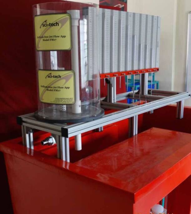
Orifice is a simple device used to measure fluid flow rate in pipes. The flow rate is obtained by measuring the pressure loss across the calibrated orifice. Calibration of the orifice plate consists of determining the co-efficient of discharge which is the ratio of the measured actual discharge through the orifice to the theoretical discharge obtained from calculations. Study of the trajectory profiles of water jets issuing from the orifice and comparison with the calculated profile shapes is an interesting exercise to the student of hydraulics and fluid mechanics. Sci-tech Orifice and Free Jet Flow Apparatus Model FM 17 has been designed to enable students to determine the co-efficient of discharge of sharp edged orifice and to study the trajectory profiles of water jets issuing from the orifice. It consists of a vertically mounted constant head transparent water tank. Water is supplied from the hydraulic bench or any closed circuit controlled water supply system. The orifice is installed with the axis horizontal on the wall at the base of the tank using special fittings flush with the inside surface. The head above the orifice is maintained constant using adjustable overflow pipe and the level is indicated by the level scale. The flow rate through the orifice can be varied by adjusting the level of the overflow pipe suitably and hence the head over the orifice. Water emerging from the orifice is collected in the measuring tank of the hydraulic bench to make actual discharge measurements. A jet trajectory tracing device with a plotting board and a number of depth gauge pins enables to plot the jet trajectory directly on the graph paper. The equipment is designed to fit into the FM100 Hydraulic Bench or any other standard hydraulic bench models. Adjustable feet are provided to permit accurate leveling of the equipment before use. The complete unit is manufactured from corrosion resistant materials. OPTION: Computer Based Learning Software is included to enable students understand and conduct experiments, tabulate results and plot graphs. The Sci-tech Orifice and Free Jet Flow Apparatus is an important experimental set-up for any Fluid Mechanics and Hydraulics Laboratory of an educational institution. Experiments Following is the list of experiments that can be carried out using the Orifice and Free Jet Flow Apparatus: 1. Determination of co-efficient of velocity for an Orifice. 2. Determination of co-efficient of discharge for an Orifice. 3. Study of the co-efficient of discharge of Orifice with flow under constant head and flow under varying head. 4. Study of co-efficient of discharge at various values of head over the Orifice to study the influence of flow Reynolds number. 5. Comparison of the measured trajectory of the jet with the trajectory calculated from simple theory. 6. Study of trajectory of jet at various values of head over the Orifice. 7. Comparison of results obtained for two different diameter orifices. Specifications: Sharp Edged Orifice, Two Nos., diameters: 3.0mm and 6.0mm. Quandrant Edge Orifice Sharp Edge Orifice Cylindrical methacrylate tank, clear transparent, 300mm diameter, 500mm height, Supported on tripod legs with provision for leveling. Maximum constant head: 420mm. Max. Flow rate: 14LPM. Jet Trajectory Tracing Device with silkscreen printed scale, No. of Jet trajectory probes: 8. Pitot tube, positioning unit and manometer to measure the actual head over the Orifice. Optional Computer Based Learning Software is included to enable students understand and conduct experiments, tabulate the results and plot graphs. (OPTION: Two Nozzles of standard dimensions and different geometries can also be supplied on request to enable conducting experiments for the determination of co-efficient of discharge and jet trajectory at various flow conditions. The nozzles can be mounted flush with the inside surface of the tank.) The manual describing the theoretical and practical aspects of the apparatus
Additional Information:
Payment Terms : T/T
Delivery Time : 8 weeks
Various devices are available to measure the fluid flow rate. Majority of these devices use the Bernoullis theorem which states that the sum of pressure head, velocity head and the potential head is constant along a stream line for a steady, in viscid and incompressible flow of fluid. Measurement of fluid flow rate is important to the students of mechanical, chemical, civil and several other branches of engineering.
The Sci-tech Flow Meter Demonstration Apparatus Model FM 18 is a mobile bench top unit and has been designed to demonstrate the working of the venture meter, orifice plate and the turbine flow meter. The apparatus consists of a piping network with flow meters located suitably and instrumented with static pressure taps. Provision is made to calibrate and determine the co-efficient of discharge of venture meter and orifice plate. The turbine flow meter is used as a reference. The flow meters are calibrated by static pressure measurements using manometers and actual flow measurements using graduated measuring tank of the hydraulic bench. Wall pressure tapings are provided along the converging and diverging portions of the venture-meter to measure the static pressure distribution. Multi-tube manometer having a manifold with an air bleed valve is supplied to make static pressure measurements. The manometer is pressurized by a hand pump.
Water is supplied by a hose connection to the inlet and flow rate is varied by a valve at the outlet. The complete unit is manufactured from corrosion resistant materials. The FM100 Hydraulic Bench or any other standard hydraulic bench models can be used to supply water.
Specifications:
1. Piping system, 25mm nominal bore, and stainless steel.
2. Venturi meter, transparent, made of clear Acrylic and having convergent and divergent portions, throat diameter: 15mm, maximum diameter: 31.75mm, upstream taper: 210, downstream taper: 140. No. of static pressure taps: 7.
3. Orifice plate, 20mm nominal diameter.
4. Turbine flow meter, 2 - 20 liters/min, max. flow rate.
5. Multi-tube manometer, 0-440 mm water column, No. of tubes: 8 with hand pump.
Options:
1. Other types of water flow measuring devices such as (a) Sudden Enlargement, (b) Elbow (c) Variable Area Rotameter (d) Nozzle and (e) Pitot-tube with necessary pressure instrumentation can be included in the apparatus to suit the requirements of the user on request.
Experiments:
1. Familiarization with static pressure measurements.
2. Familiarization with flow measurement techniques.
3. Determination of co-efficient of discharge of orifice plate.
4. Determination of co-efficient of discharge of venturimeter.
5. Demonstration of continuity equation.
6. Demonstration of Bernoullis theorem.
7. Study of static pressure variation along the venturi at different flow rates.
8. Study of working and calibration of turbine flow meter.
Measurements:
1. Static pressures along the venturi meter.
2. Static pressures across orifice plate.
3. Flow rate using turbine flow meter.
4. Actual volume flow rate using Hydraulic Bench or graduated tank.
Additional Information:
Payment Terms : T/T
Delivery Time : 8 weeks


Cavitation is a phenomenon in which vapor pockets are released in the liquid flow because of the reduction in the local static pressure. Cavitation occurs in any device handling liquids whenever the local static pressure reduces below the vapor pressure of the liquid. The vapor bubbles formed during cavitation may cause the flow to become unsteady and reduce the performance of devices such as pumps and turbines. Collapsing of vapor bubbles on surfaces cause erosion damage or surface pitting damaging components. Understanding of cavitation phenomenon is important to the students of marine, civil, hydraulic, mechanical, chemical and several other branches of engineering.
The Sci-tech Cavitation Demonstration Apparatus Model FM 19 is a compact bench top unit and has been designed to visualize and study the cavitation phenomenon in water flow. The apparatus consists of a venturi - shaped test section made of clear acrylic to enable visualization of formation of bubbles and subsequent collapse of bubbles in the flow. The upstream section of the venturi is connected to the hydraulic bench or any suitable source of water. The FM00 Hydraulic Bench or any other standard hydraulic bench models can be used. Cavitation is obtained by reducing pressure at the throat according to Bernoulli equation by varying the flow rate. Flow control valves at the upstream and downstream ends of the test section allow control of flow. Static pressures at the upstream section and the throat are measured using pressure gauges. The flow rate is measured using turbine flow meter. The apparatus can be mounted on the hydraulic bench and is provided with quick release fittings for easy connections. The complete unit is manufactured from corrosion resistant materials.
OPTION
Computer based learning Sci-cal software is included to enable students understand and conduct experiments, tabulate results and plot graphs. The Sci-tech Cavitation Demonstration Apparatus is an important experimental set-up for any Fluid Mechanics and Hydraulics Laboratory of an educational institution.
Experiments
1. Visualization of cavitation phenomena.
2. Demonstration of reducing cavitation by increasing static pressure in the flow field.
3. Comparison of experimental and theoretical pressures for cavitation.
4. Determination of cavitation number
Measurements:
1. Static pressure at the upstream and the throat.
2. Actual volume flow rate using turbine flow meter or Hydraulic Bench.
Specifications:
1. Piping system and quick release fittings, 15mm nominal bore, and stainless steel.
2. Venturimeter, transparent, made of clear Acrylic and having convergent and divergent portions, throat diameter: 7.5mm, maximum diameter: 15mm, upstream taper: 150, downstream taper: 60.
3. Turbine flow meter, 2 liters/s max. flow rate.
4. Upstream pressure gauge: 0 to 1 bar with pressure tubing.
5. Throat vacuum gauge: -1 to 0 bar with pressure tubing.
6. Instrument mounting panel.
7. Sci-cal Computer based learning software.
Options
1. A self contained unit of Cavitation Demonstration Apparatus mounted on a mobile platform with a flow controlled closed circuit water circulation unit consisting of centrifugal pump, corrosion resistant sheet metal measuring tank and a sump tank will be supplied on request.
2. Electronic pressure transducers with digital display of pressures can be supplied instead of pressure gauges on request.
3. Computer based Sci-cal data acquisition system for acquiring pressure data can be supplied on request.
Additional Information:
Payment Terms : T/T
Delivery Time : 8 weeks

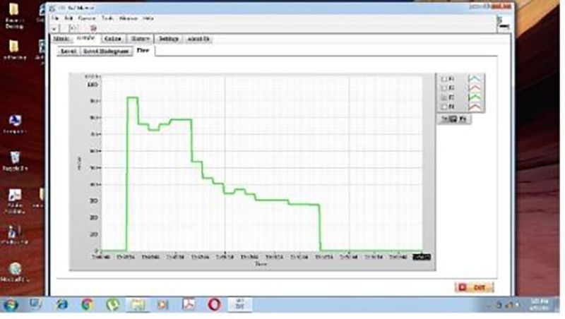
Francis turbine is a radial flow reaction turbine. Energy of water is transferred to the turbine runner by changes in both velocity and pressure. Water enters the turbine unit circumferentially through the spiral turbine casing. It enters the periphery of the stationary guide vanes and flows radially inwards through the runner. After passing through the runner, flow is discharged nearly axially through a draft tube before entering the tail race. The torque developed in the runner is converted into useful work. Francis turbines are used in hydro-electric power plants operating with water source available at medium heads (say, 15 to 300m of water) and volume flow rates. It is essential for students to understand the operation and performance characteristics of Francis turbines. Sci-tech Francis Turbine Demonstrator Trainer Model FM 21 is an experimental set-up necessary for any hydraulic machinery and fluid mechanics laboratory of an educational institution. The Sci-tech Francis Turbine Demonstrator Trainer Model FM 21 has been designed to enable students to study the operation and performance characteristics of a typical single stage Francis turbine. The unit has a sump tank and a centrifugal pump driven by electric motor to supply and re-circulate water. The turbine is mounted with the axis horizontal on the top of the robust mobile frame. Water enters the turbine casing through a variable area flow meter. A hand operated valve is provided at the inlet to control inlet head and flow rate. Inlet head is measured using a pressure gauge. After passing through the stationary guide vanes and runner, water is discharged through tube to the sump tank. A ring mechanism is provided to vary the position of inlet guide vanes. The flow rate though the runner can be controlled by operating inlet guide vanes. Transparent observation window is provided to see operation of inlet guide vane mechanism. Power generated in the turbine is absorbed by a disc brake dynamometer and the torque is measured using load cells. Turbine shaft speed is measured using digital tachometer. Instrumentation and control panel is included. The complete unit is manufactured from corrosion resistant materials. The Sci-tech Francis TurbineDemonstration Apparatus Model FM 21 is an important experimental set-up for any Fluid Mechanics and Hydraulics Laboratory of an educational institution. Optional Sci-Cal Computer based learning software is included to enable students understand and conduct experiments, tabulate results and plot graphs. List of Experiments 1. Study of construction of Francis Turbine 2. Determination constant head characteristics curve 3. Determination of constant speed characteristics curves 4. Determination of constant efficiency curves. Important Features and Specifications: Standard Model: Turbine: output: 35W at 3000rpm, Water rate @. 40L/min, H=0.8m Impeller Impeller blades: 10 Impeller dia: 20mm Impeller inlet height: 14.5mm Impeller outlet dia: 50mm Guide vanes: 6 adjustable with positioning marks Measuring ranges Braking force: 20N Pressure Gauge: 0.5bar High Capacity Model: Functional model of Francis turbine, with a distributor with adjustable guide vanes that allows to control the water angle of incidence of the turbine: Diameter of the turbine: 52 mm. Speed range: 0-1200 r.p.m. approx. Rotor: Number of blades of the turbine: 15. Stator: Number of adjustable guide vanes of the distributor: 10. Braking system: Band brake with adjustable braking tension. Load cell-force sensor, range: 0-20N. Computer controlled water pump, with variable speed: Maximum height: 70 m. Maximum pressure: 7 bar. Maximum water flow: 120 l./min. Power: 1.5 kW. Transparent wa
Additional Information:
Payment Terms : T/T
Delivery Time : 16 weeks
Sci-tech Centrifugal Blower Test Apparatus Model FM 22 enables to study of performance of centrifugal blower (Compressor) & its calculation is main focus in designing this trainer. System is having Driving motor, Centrifugal Blower (Compressor), inlet & outlet ducts. The centrifugal blower & motor are mounted on a rigid stand. Measuring instruments are provided to measure Suction & Delivery pressure, Air Flow rate, Blower Speed, Motor Power Consumption. Sci-tech has designed the system having feature of easy to operate; demonstrated & requisite experimentation can be performed.
EXPERIMENTS POSSIBILITIES
Calculation of centrifugal fan / blower performance. To determine volumetric Efficiency, Mechanical Efficiency.
Plotting of intake volume flow rate versus delivery flow rate for varying duty.
Calculation of centrifugal fan / blower performance under variable speed, required pressure & capacity (with optional accessories).
SYSTEM SPECIFICATIONS
Centrifugal pump impeller forward curved, backward curved, radial tipped, airfoil bladed, open type or with shrouds.
Axial flow pump impeller
Mixed flow pump impeller
OPTIONAL ACCESSORIES
Additional Information:
Payment Terms : T/T
Delivery Time : 8 weeks
Study of pipe friction and hence the pressure loss in pipes is important in view of the pumping power requirements in any pipe system. Sci-tech Pipe Friction Apparatus Model FM 23 is an experimental setup necessary for any Fluid Mechanics and Hydraulics Laboratory of an educational institution.
Sci-tech Pipe Friction Apparatus Model FM 23 has been designed to enable students to determine the friction factor in the pipe flow and to study the effect of change in flow velocity on pipe friction. The Laminar and turbulent flow regimes can be obtained by varying the flow velocity and hence the flow Reynolds number. The apparatus consists of a horizontal test pipe with static pressure tapings at the upstream and downstream ends to measure head loss due to friction to determine the friction factor. Extra pipe lengths are provided at the inlet and exit to allow the flow to become fully developed and to damp out the flow disturbance originating from the valves and fittings. The test pipe is mounted on a support frame and there is a provision for leveling. Water is supplied from the hydraulic bench (for higher flow rates) and the constant head feeding tank (for lower flow rates). Pressure drop along the test pipe length is measured using the U-tube mercury manometer or the pressurized water manometer depending upon the flow velocity. These manometers are mounted on a display panel with calibrated scales. The flow rate and hence the velocity though the test pipe is controlled by a regulation valve at the exit and the flow rate is measured by the flow meter or the measuring tank of the hydraulic bench. The friction factor is determined from the measured pressure loss and flow velocity. Experiments can be conducted at various flow velocities or Reynolds numbers to obtain friction factors in laminar or turbulent flow regimes. The complete unit is manufactured from corrosion resistant materials. The FM100 Hydraulic Bench or any other standard hydraulic bench models can be used to supply water.
Computer Based Learning Software is included to enable students understand and conduct experiments, tabulate results and plot graphs.
The Sci-tech Pipe Friction Apparatus Demonstration Model FM 23 is an important experimental set-up for any Fluid Mechanics and Hydraulics Laboratory of an educational institution.
Important Features and Specifications:
1. Test pipe, stainless steel, 3mm bore, 650mm long with two static pressure taps at 500mm apart.
2. Feeding tank, capacity: 10 liters, constant water head: 600mm length & 140mm diameter ID.
3. Mercury U-tube manometer, range: 200mm.
4. Pressurized water manometer, range: 400mm WC.
5. Flow meter, range: 2 Lpm with needle valve to regulate flow rate.
6. Ancillaries include measuring cylinder (5 liter capacity), hand pump and a sample of test pipe (100mm long).
7. Portable digital manometer (Optional)
Options:
1. A self contained unit of the Pipe Friction Apparatus mounted on a mobile platform and with a flow controlled closed circuit water circulation unit consisting of centrifugal pump, flow meter, corrosion resistant sheet metal measuring tank and a sump tank will be supplied on request.
2. A digital pressure meter can be supplied as an alternative to the mercury U-tube manometer on request.
List of Experiments:
1. Familiarization with pressure measurements and the working of U-tube manometer.
2. Study of loss of head due to friction in a circular pipe at various mean flow velocities.
3. Study of friction factors in laminar and turbulent flow regimes.
4. Demonstration of the law of pipe friction resistance in laminar to turbulent flow regimes.
5. Establishment of critical Reynolds number.
6. Comparison of experimental results of friction factor Reynolds number relationship with the well-known Moodys diagram.
Additional Information:
Payment Terms : T/T
Delivery Time : 8 weeks


Sci-tech Drain Permeameter Model FM-36 is suited for use both as a teaching and demonstration tool and for laboratory testing and research. The equipment consists of a 100mm diameter transparent column which may be filled with any soil type. A removable base section is provided into which the filter material to be investigated is placed.
Water is added to the column under a constant head and permeating water and soil is collected at the base. The discharge from the drain can be monitored to assess the efficiency of the filter material. The apparatus is supported on a sturdy metal frame and may be conveniently placed on a laboratory bench close to a water supply and drain.
Specifications
Sci-tech Drain Permeameter Model FM 25 comprises of:
- Acrylic column, 100mm diameter supported on a metal stand;
- Removable test section is provided at the base of the column to house the filter medium to be tested;
- The apparatus, which may be bench-mounted,
- Supplied complete with user instructions and manuals.
Experiments:
As a result of using this equipment students will be able to:
1. Determine relative efficiencies of drain filter materials
2. Select optimum filter/soil combinations.
Additional Information:
Payment Terms : T/T
Delivery Time : 8 weeks

The sum of pressure head and velocity head is constant along a horizontal stream line in a steady, inviscid and incompressible flow of fluid. The Sci-tech Pressure Distribution in Venturi Nozzle Model FM 26 Apparatus is a bench top unit and has been designed to measure the variation of static pressure and flow velocity in pipe flow having venturi and nozzle. The apparatus consists of transparent venturi tube and nozzle mounted in a horizontal pipe line. Wall pressure tapings are provided along the converging and diverging portions of the venturi and nozzle surface to measure the static pressure variation. Pitot probes are provided at suitable locations along the centre line of the venturi and nozzle to measure total head. Static and total pressures are measured using multi-tube manometer having a manifold with an air bleed valve. Manometer can be pressurized by a hand pump. Flow meter is provided to measure flow rate.
rnThis apparatus can also be used to conduct laboratory experiments to (a) demonstrate continuity and Bernoullis equations and (b) determine the co-efficient of discharge of venturi and nozzle to use as flow measurement devices. The FM00 Hydraulic Bench or any other standard hydraulic bench models can be used to supply water. Water is supplied by a hose connection at the inlet and controlled by a valve at the outlet. The complete unit is manufactured from corrosion resistant materials.
rnrn
OPTION:
rnSci-Cal Computer based learning software is included to enable students understand and conduct experiments, tabulate results and plot graphs. The Sci-tech Pressure Distribution in Venturi Nozzle Apparatus is an important experimental set-up for any Fluid Mechanics and Hydraulics Laboratory of an educational institution.
rnrn
Following is the list of experiments that can be carried out using the Bernoullis Theorem Demonstration Apparatus:
rnrn
rn
rn
Measurements:
rnrn
rn
rn
rn
rn
Important Features and Specifications:
rnrn
rn
Option: A self contained unit of Pressure Distribution in Venturi Nozzle Apparatus mounted on a mobile platform with a flow controlled closed circuit water circulation unit consisting of centrifugal pump, flow meter, corrosion resistant sheet metal measuring tank and a sump tank will be supplied on request.
Additional Information:
Payment Terms : T/T
Delivery Time : 4 weeks

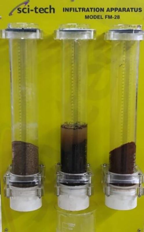
Sci-tech Infiltration Apparatus Model FM-28 provides a simple but effective laboratory demonstration of the infiltration processes which are fundamental to any form of irrigation.
rnThe unit comprises three transparent cylinders in which soil samples are placed. Water poured onto the soil surface can then be observed as it infiltrates the sample.
rnEach cylinder features a graduated scale so that observations may be quantified. Each cylinder incorporates an air breather and a perforated base plate to facilitate drainage without undue soil loss.
rnSci-tech Infiltration Apparatus comprising: three graduated Perspex cylinders, resting on a permeable support screen, into which soil samples are placed.
rnThe complete apparatus is supported by a metal stand and may be bench mounted; complete with user instructions and manual.
rnSpecifications
rnAluminum Structure:
rnThis is made up of aluminum structure with 3 Glass Pipes mounted over Eurobond sheet mounted above.
rnSize: 0.5m x 0.5m x 0.9m
rnrnMeasuring Glass for Experiments:
rnGlass of Inside diameter 75mm and Length 500mm, with measuring scale attached over glass pipes.
rnNumber of glass 03
rnrnrn
Components
rnAluminum Structure
rnGlass Tubes 3 Nos.
rnPipe Bracket
rnGaskets
rnMeasurement Scale
rnTool Set and Accessories
rnrn
rn
Experiments Possibilities
rnDemonstration of the effect of crusting on infiltration
rnUnderstand the effects of soil texture and structure on infiltration
rnUnderstand the effects of existing soil moisture conditions on infiltration
rnDemonstration of relationship between soil type and infiltration and penetration rates
rnDemonstration of the relationship between soil particle size and infiltration
rnThe effect of organic matter content on infiltration and penetration rate
rnThe effect of non-homogeneous soil strata on infiltration and penetration rates
rnThe effect of moisture content on infiltration and penetration rates
rnThe effect of straw mulch on infiltration rate
rnSoftware:
rnSci-Cal DAQ Software & real time acquisition
Additional Information:
Payment Terms : T/T
Delivery Time : 4 weeks


Sci-tech Falling Sphere Viscometer & Particle Drag Coefficient Apparatus Model FM 29 is designed to enhance student study of liquid viscosity and particle drag coefficient, it consists of two precision bore glass tube mounted on wall mounting frame with back light source for easy visualize the fall of particle.
rnStudents can place the test sphere on to the top of tube, let it fall freely, with stop watch measured the time
rntake to fall to the bottom. A valve system at the bottom of tube allows to remove the sphere easily.
rnrn
rn
rn
Technical specification
rnStreamline shape test sample, 2nos
rnrn
rn
Experiments
rnDetermine the drag coefficient of various shape particle.
Additional Information:
Payment Terms : T/T
Delivery Time : 8 weeks
Kaplan Turbine is an axial flow reaction turbine named in honour of Dr. B. Kaplan, a German Engineer.
rnSci-tech Kaplan Turbine Demonstrator Trainer Model FM 30 is suitable for low head. The power produced by a turbine is proportional to QH. As the head (H) decreases the J discharge (Q) must increase to produce the same power. The present set-up consists of a scroll casing housing a runner. Water enters the turbine through the stationary guide vanes and passes through the runner axially. The runner has a hub and airfoil vanes, which are mounted on it.
rnIn Sci-tech Kaplan Turbine Demonstrator Trainer Model FM 30 the water is fed to the turbine by means of Centrifugal Pump of a hydraulic bench, FM 100F. The runner is directly mounted on one end of a central SS shaft and other end is connected to a brake arrangement. A transparent hollow cylinder made of acrylic is fitted in between the draft tube and the casing for observation of flow. Load is applied to the turbine with the help of rope brake arrangement so that the efficiency of the turbine can be calculated. The set-up is supplied with control panel. A draft tube is fitted on the outlet of the turbine.
rnThe set-up is complete with guide mechanism. Pressure and Vacuum gauges are fitted at the inlet and outlet of the turbine to measure the total supply head on the turbine
rnSci-tech Kaplan Turbine Test Rig FM 30 is designed to show the operation & performance characteristics of Kaplan Turbine. A vertical shaft Kaplan Turbine to develop from 50 Watts to 1000 Watts at 1500 rpm, rope brake arrangement can be coupled for loading.
rnrn
Structural Specifications
rn1) Stainless structure.
rn2) Screws, nuts, plates and all the metallic elements in stainless steel.
rn3) Diagram in the front panel with similar distribution to the elements in the real unit.
rn4) Quick connections for adaptation to feed hydraulics source.
rnrn
rn
Technical Data
rn(A)Kaplan Turbine:
rnRating: 50W
rnFunctional model of a Kaplan turbine, with a ring of wicket gates that allows to control the water flow in the turbine.
rnSpeed range: 0 2500 r.p.m.
rnNumber of blades of the turbine: 4.
rnDiameter of the turbine: 52 mm.
rnNumber of wicket gates of the ring: 8.
rnBraking system:
rnBand brake.
rnAdjustable braking tension.
rnRadius of the pulley of the brake: 50 x 10-3 m.
rnTransparent water tank, capacity: 120 l. approx.
rnInstrumentation and sensors:
rn2 Water pressure sensors, range: 0 - 100 PSI.
rnForce sensor (load cell), range: 0 - 20 N.
rnSlot sensor to measure the speed, range: 0-20000 r.p.m.
rnWater flow sensor, range: 2 - 150 l./min.
rnWater pump:
rnMaximum height: 20 m.
rnMaximum pressure: 2.2 bar.
rnMaximum water flow: 160 l./min.
rnPower: 0.5 kW.
rnSpeed adjustable through variable-speed drive.
rnOptional:Sci-cal Software & Interface
rnExperiments
rn1. Study of construction of Kaplan turbine
rn2. Determination constant head characteristics curve
rn3. Determination of constant speed characteristics curves.
rn4. Determination of constant efficiency curves.
Additional Information:
Payment Terms : T/T
Delivery Time : 12 weeks
Study of open channel flows is a subject of interest in basic fluid mechanics and Hydraulics. A flow channel with a provision to control depth of flow over in the channel can provide a very useful tool to study several aspects of open channel flows. Adjustable Bed Flow Channel Unit is an essential equipment for fluid mechanics, hydraulics, civil, mechanical and related laboratories in science and engineering institutions.
rnThe Sci-tech 10M LONGAdjustable Bed Flow Channel Unit Model FM 32/10Mis suitable for demonstrations and teaching of open channel flows. By closing the top of the channel, the unit can also be used to demonstrate duct flows. The complete unit is mounted on a mobile platform fixed on castor wheels. The apparatus is self-sufficient with water recirculation system consisting of flow inlet tank, centrifugal pump, flow control valves, discharge tank, water flow meter and sump tank. The inlet tank consists of baffle plate and screens to reduce disturbances in the flow. The discharge tank consists of adjustable over flow weir which can be adjusted to control flow conditions in the working section. The working section is transparent and is made of clear acrylic. Other components of the unit are made of corrosion resistant materials. Experiments can be conducted in both open channel flow and duct flow modes. The channel consists of adjustable floor section which along with the transition section can be raised or lowered usingsuitable inserts. The combination of adjustable floor and upper boundary plate enable formation of various types of ducts to conduct experiments. Flow control valve is provided upstream of the inlet tank control flow rate. The mid-section of the upper boundary wall is made removable for fast changing and installation of models in the working section. Total pressure probes and static pressure tapings are provided at five locations along the working section. Total pressure probes can be moved vertically and fixed at different positions over the depth of the channel. Different models, such as hump, weirs etc., required to carryout studies mentioned in the list of experiments are supplied. Provision is made to fix models in the working section using suitable fixtures.
rnSpecifications for 10m Channel Flume:
rnrn
| rn
List of Experiments:
rnrnAdditional Information:
Payment Terms : T/T
Delivery Time : 16 weeks
The Sci-tech Adjustable Bed Flow Channel Unit Model FM 32 - 15M to 20Mis suitable for demonstrations and teaching of open channel flows. By closing the top of the channel, the unit can also be used to demonstrate duct flows. The complete unit is mounted on a mobile platform fixed on castor wheels. The apparatus is self-sufficient with water recirculation system consisting of flow inlet tank, centrifugal pump, flow control valves, discharge tank, water flow meter and sump tank. The inlet tank consists of baffle plate and screens to reduce disturbances in the flow. The discharge tank consists of adjustable overflow weir which can be adjusted to control flow conditions in the working section. The working section is transparent and is made of clear acrylic. Other components of the unit are made of corrosion resistant materials. Experiments can be conducted in both open channel flow and duct flow modes. The channel consists of adjustable floor section which along with the transition section can be raised or lowered using suitable inserts. The combination of adjustable floor and upper boundary plate enable formation of various types of ducts to conduct experiments. Flow control valve is provided upstream of the inlet tank control flow rate. The mid-section of the upper boundary wall is made removable for fast changing and installation of models in the working section. Total pressure probes and static pressure tapings are provided at five locations along the working section. Total pressure probes can be moved vertically and fixed at different positions over the depth of the channel. Different models, such as hump, weirs etc., required to carry out studies mentioned in the list of experiments are supplied. Provision is made to fix models in the working section using suitable fixtures. Specifications for Channel Flume: General: Open channel flow and duct flow modes of operation. Self-contained unit consisting of diaphragm flow control valve, inlet tank with baffle plate and screens, centrifugal pump, flow meter, discharge tank with adjustable overflow weir and sump tank. Transition section and adjustable floor section. Floor inserts for converging and converging-diverging duct flows. Upper boundary plate. Weirs as per accessories list Models: hump, sluice gate, etc. Model fixtures as per accessories list. Pressure probes with fixtures to vary position. Static pressure taps. Specifications 1. Walls Toughened glass: 10 12mm thick 2. Bed exclusively fabricated from 1.5 2mm stainless steel 3. End Tanks FRP (Fiberglass Reinforced Plastic) 4. Sump tanks in SS & pipe network PVC (Polyvinyl Chloride) & PE (polyethylene) 5. Pump Close-coupled centrifugal 6. Flow regulation valve Hand wheel operated butterfly valve 7. Tilt parameters +ve slope 20 & -ve slope max 10 8. Flow meter Electromagnetic 9. Maximum flow rate 30 Litres/sec 10. Bed stability 1.0mm (typical) at 400mm water depth 11. Side wall stability 0.5mm (typical) at 400mm water depth 12. Width 0.3m Depth 0.45m 13. Electric supply 3Ph, 50Hz 14. Pitot tube and manometer 15. Culvert fitting, one edge square, one rounded 16. Flow splitters, central wall with various nose pieces 17. Free overflow spill complete with ski jump, sloping apron and bleed reverse curvature attachments 18. Syphon spillway and air regulated syphon 19. Differential pressure sensor for use with Pitot tube 20. Wave generator and wave absorbing beach 21. Comprises two beds of different roughness. Gravel Bed and Corrugated Bed.(Model 32RB). Each 2.5m long consists of three sections additional total 6 sections additional. 22. False floor sections for gradually varied profiles 23. Spirit level mounted on every 2.5m section 24. 2
Additional Information:
Payment Terms : T/T
Delivery Time : 24 weeks
Study of open channel flows is a subject of interest in basic fluid mechanics and Hydraulics. A flow channel with a provision to control depth of flow over in the channel can provide a very useful tool to study several aspects of open channel flows. Adjustable Bed Flow Channel Unit is an essential equipment for fluid mechanics, hydraulics, civil, mechanical and related laboratories in science and engineering institutions.
The Sci-tech Adjustable Bed Flow Channel Unit Model FM 32is suitable for demonstrations and teaching of open channel flows. By closing the top of the channel, the unit can also be used to demonstrate duct flows. The complete unit is mounted on a mobile platform fixed on castor wheels. The apparatus is self sufficient with water recirculation system consisting of flow inlet tank, centrifugal pump, flow control valves, discharge tank, water flow meter and sump tank. The inlet tank consists of baffle plate and screens to reduce disturbances in the flow. The discharge tank consists of adjustable over flow weir which can be adjusted to control flow conditions in the working section. The working section is transparent and is made of clear acrylic. Other components of the unit are made of corrosion resistant materials. Experiments can be conducted in both open channel flow and duct flow modes. The channel consists of adjustable floor section which along with the transition section can be raised or lowered using suitable inserts. The combination of adjustable floor and upper boundary plate enable formation of various types of ducts to conduct experiments. Flow control valve is provided upstream of the inlet tank control flow rate. The mid-section of the upper boundary wall is made removable for fast changing and installation of models in the working section. Total pressure probes and static pressure tapings are provided at five locations along the working section. Total pressure probes can be moved vertically and fixed at different positions over the depth of the channel. Different models, such as hump, weirs etc., required to carryout studies mentioned in the list of experiments are supplied. Provision is made to fix models in the working section using suitable fixtures.
Specifications:
Options:
Experiments:
Additional Information:
Payment Terms : T/T
Delivery Time : 12 weeks
Study of open channel flows is a subject of interest in basic fluid mechanics and Hydraulics. A flow channel with a provision to control depth of flow over in the channel can provide a very useful tool to study several aspects of open channel flows. Adjustable Bed Flow Channel Unit is an essential equipment for fluid mechanics, hydraulics, civil, mechanical and related laboratories in science and engineering institutions. Sci-tech Fixed Mobile Bed Unit FM32F is a particularly useful unit to demonstrate the fluidization phenomenon in engineering. It makes it possible to study different situations of flow and mobile bed visualization related to civil engineering structures. This unit may be used mainly in two study fields. The first one is the investigation of mobile beds, which are related to water courses and civil engineering structures. The second one is related to the visualization of the flow in two dimensions. FM 32F consists of an horizontal channel through which a current of water flows slowly and at a constant depth. The working section is 2000 x 610 mm. Study with the channel is simple thanks to the installation of different models and structures in it, making the flow circulate around them. The unit is self-contained and it consists of an inlet tank with adjustable gate, channel with sand filters, discharge tank, water storage tanks, centrifugal pump, electromagnetic flow meter and set of models. The practical exercises with this unit are carried out by using water and sand. The sand bed can be placed on a polycarbonate sheet, which is located inside the flow channel. Specifications The Fixed Mobile Bed is mounted on a metallic structure. This unit is divided into three sections: inlet tank, working section (channel) and discharge tank. These sections are assembled through joints in order to get a complete assembly. There is a sand filter between the end of the channel and the discharge tank. Stainless steel inlet tank with adjustable gate. It is supplied with a control at the upper side of the tank which makes it possible to change the slope of such gate. Dimensions: 530 mm x 710 mm x 530 mm. Flow channel made of stainless steel, including a main rail with millimeter rulers (Longitudinal cross piece). A structure which includes a sub-rail (transversal crosspiece) is supported on the rail. It makes it possible to put a depth gauge to measure the water level and determine the outline of the sand bed during the development of the practical exercises. Dimensions: 2000 mm x 710mm x 350 mm. The working section is 2000mm x 610 mm, and max. water depth is 120 mm approx. The practical exercises with this unit are carried out by using water and sand. The sand bed can be placed on a polycarbonate sheet, which is located inside the flow channel. Discharge tank made of stainless steel with overflow. It is divided into two parts, the one closer to the channel enables the sedimentation of sand, whereas the second part enables the removal of the water which overflows from the first section. Dimensions: 850 mm x 710 mm x 530 mm Two storage tanks made of polyethylene of approximately 250 l. each one. It has a filter at the pump 's inlet to retain possible residues. Centrifugal pump: flow range: 7.2 - 18 m /h; height: 14.4 19.70 M.W.C. Electromagnetic flow meter: flow range: 10-70 l./min. Membrane valve. Two different size gates. A set of models included: Bridge piers models: 2 rectangular models. 4 cylindrical models. 4 square models. 2 profiled rectangular models. 2 rectangular models with rounded ends Triangular model. Asymmetrical aerofoil model. Six baffles to direct the water flow during the experimental tests. A set of 12 L shaped profiles. Three pairs of different angles to build additional models Diagram in the front panel with similar distribution to the elements in the real unit. Electronic console, including: Motor-pump starter. Flow meter measurement display. Cables and accessories, for normal operation. Manuals: Thi
Additional Information:
Payment Terms : T/T
Delivery Time : 16 weeks
Fluid mechanics is an important subject and has applications in several areas including air conditioning, aerospace, automobile, and industrial air distribution systems. Study of air flows and its measurement is important for understanding the basic principles of fluid mechanics. Sci-tech Air Flow Studies Apparatus Model FM 34 is important equipment for laboratories in certificate level, diploma and degree level courses of mechanical, civil, chemical, aeronautical, environmental and related branches of engineering of any educational institutions. Sci-tech Air Flow Studies Apparatus Model FM 034 is a self-contained and compact unit designed to demonstrate the basic fluid mechanics principles by conducting measurements of important characteristics associated with a typical industrial air distribution system. The apparatus will enable students to study the principles of fluid mechanics by analysing the flows in ducts and jets. The apparatus consists of a long smooth walled stainless-steel pipe with a bell mouth entry connected to the suction side of the centrifugal fan. The bell mouth entry prevents flow separation from the walls of the pipe at the entrance. The turbulence in the pipe is reduced because of the use of suction fan. Flow straightening vanes are provided to minimize formation of vortices resulting in reduction of turbulence in the test pipe. The fan discharge pipe terminates in a flow control damper (for closed circuit operation) or a plate containing an aperture to obtain a jet for measurements. Two nozzles and an orifice plate are provided to measure flow rate by differential static pressure measurements. Static pressure taps are provided along the length of the pipe at equal intervals to measure pressure gradient along the pipe. A bend or mitered cascade elbow can be fitted at the inlet of the pipeline to measure the pressure loss. Provision is made to measure the boundary layer growth and the mean velocity profiles at six stations along the pipe length by traversing the Pitot probe. Arrangement is provided to study the characteristics of the jet flow by traversing the Pitot-static probe in the jet flow. The probe can be traversed in two perpendicular directions at several stations along the length of the jet to study the jet spread or dispersion. Pressures are measured using a 15-tube inclined manometer. The inclined manometer is provided to make sensitive pressure measurements. The complete equipment is mounted on a steel frame having the provision for levelling. Specifications 1. Centrifugal fan, capacity about 250 LPS at STP. 2. Velocity in pipe: 35 m/s (max.) 3. Pipe inlet diameter: 80 mm.(approx.) 4. Length of pipe: 2.5m 3m. 5. Bell mouth entry. 6. Interchangeable nozzles (2 Nos.): dia. 50 and 80mm. 7. Orifice plate ID: 50mm. 8. Jet discharge pipe dia.: 30mm. 9. Jet traverse range: 160mm X 600mm. 10. Multi-tube inclined manometer, 15 tube, 0.6m long. 11. Manometer fluid: Kerosene. 12. Bend and mitred cascade elbow. 13. Pitot probe. 14. Pitot-static probe. 15. Probe traverse for duct flow measurements. 16. Probe traverse for jet flow measurements. 17. Support system. Technical Specifications A. Centrifugal fan, with speed control: Max. volumetric flow rate: 1800 m/h. Max. motor power: 750 W. B. It includes a plate with one orifice at the discharge side of the fan to carry out air jet dispersion practical exercises, orifice diameter: 30 mm. C. Long smooth test pipe, inner diameter 81.4 mm; length: 2500 mm approx. It includes: Deflector in the inlet to prevent air-separation from the wall of the pipe and reduce the formation of vortices. Ten pressure tappings to measure the pressure gradient along the pipe A. Five stations to use the transverse Pitot tube and to determine the boundary layer growth and the development of velocity profile. B. Two Pitot tubes: Pitot tube located at the discharge of the fan, attached and properly protected
Additional Information:
Payment Terms : T/T
Delivery Time : 12 weeks

Sci-tech Axial Flow Impulse Turbine Test Apparatus Model FM 35 is widely used for pumping liquids in several applications including domestic, industrial, irrigation and drainage. The Impulse Turbine is a small-scale impulse turbine unit which is designed to be used in conjunction with the service unit. An impulse turbine uses the momentum transferred from the impact of a jet of water onto the turbine blades to generate power The Impulse Turbine is an experimental set-up necessary for any Fluid Mechanics and Hydraulics Laboratory of an educational institution.
Sci-tech Axial Flow Impulse Turbine Test Apparatus Model FM 35 consists of an inlet manifold which supplies water to four jets which are equally spaced around the turbine runner. Each of the jets can be individually controlled using ball valves. The runner itself is mounted on a horizontal shaft with a clear acrylic splash guard to allow maximum visibility of the workings. The unit incorporates a pressure sensor to measure the inlet condition of the water. This pressure can be accurately controlled using the software supplied with the service unit.
The impulse Turbines a compact unit and all components and instrumentation are placed in a robust and mobile frame. The complete unit is manufactured from corrosion resistant material.
Specifications
- Investigation of a compressed air driven axial impulse turbine
- Front panel for observing the operating area
- Distributor with 4 nozzles
- Selectable number of nozzles
- Applying a load to the turbine by using the wear-free eddy current brake
- Setting the primary pressure with the pressure reducing valve
- Valve and flow meter for setting the flow rate
- Solenoid valve as a safety device to prevent over-speed
- Determination of the torque on the turbine shaft using a force sensor
- Measurement of the turbine speed with an optical speed sensor
- Manometer for displaying pressures on the inlet and outlet side
- Digital display of speed, torque and temperature
Technical Specifications
Nozzles (four 20 nozzles and four 30 nozzles):
Throat inlet diameter: 2 mm. Throat outlet diameter: 2 mm.
Discharge angle: 20 and 30.
Turbine Rotor:
External diameter: 53 mm. Internal diameter: 45 mm. Number of blades: 40.
Inlet angle of the blades: 40. Outlet angle of the blades: 40.
Used material: brass.
Brake:
Pulley diameter: 51 mm. Effective radio: 27.5 mm.
Four Pressure sensors, range: 0 - 100 PSI (0 - 6.7 bar).
Load cell, range: 0 - 2 Kg.
Force sensor (torque), range: 0 - 20 N (maximum).
Flow sensor, range: 0 - 30 l/min.
Speed sensor, range: 0 to 20000 rpm.
Water pump, computer controlled: maximum pressure: 7 bar, maximum head: 80 m., maximum water flow: 120 l/min., power: 1.5 kW.
Water transparent tank, capacity: 110 l approx.
OPTIONS:
Sci-Cal Computer Control Software
List of Experiments:
Determining the characteristics of the turbine including the relationships of volume flow rate, head, torque produced, power output and efficiency to rotational speed.
Comparison of nozzle and throttling control of an Impulse Turbine
Additional Information:
Payment Terms : T/T
Delivery Time : 8 weeks

Sci-tech Vortex Flow Meter Model FM 36 makes it possible to study different methods of volumetric and mass flow measurement, as well as to compare continuous and intermittent methods. This module includes two continuous and two intermittent methods to carry out the experiments. The continuous methods include a vortex flowmeter and a variable-area flowmeter (or rotameter). A series of oscillating vortices, where the oscillating frequency is proportional to the flow rate, are generated in the vortex flowmeter. Dye or colouring is used to visualize such vortices. Intermittent methods include the measurement of volumetric and mass flows. A precision scale is used to measure the mass flow and compare the measurements. The water supply may be provided either from the Hydraulics Bench FM100 or from external source.
The vortex flow meter is installed in the water circuit of the Hydraulics Bench FM100 trainer. It operates according to the principle of Von Karman vortex shedding. Downstream of a dam body in a flow, vortices alternately form which are separated off by the flow. The frequency of the vortex separation to both sides of the dam body is proportional to the flow rate. The separated vortices alternately generate local vacuum which is measured using capacitive pressure sensors. The pressure signals are converted and indicated as the flow rate on a display. The necessary connections are provided so that the pressure loss can be determined with the Hydraulics Bench FM100.
Specifications
vortex flow meter as accessory hydraulic bench trainer
operation according to Von Karman vortex shedding
display indicating flow rate
connections to facilitate pressure loss measurement with the hydraulic bench trainer
connections to supply auxiliary power via the hydraulic bench trainer
vertical and horizontal installation possible
Structure of anodized aluminum and panels of painted steel.
PVC pipe to connect to a water supply of the Hydraulics Bench FM100
Needle valve to control the flow at the pipe inlet.
Vortex flow meter with flow oscillation made visible by dye injection.
Variable-area flow meter (rotameter), range: 150-1600 l./min.
Two regulating ball valves to control the flow in the vortex and variable-area flow meters.
Water tank at a constant height and connection for its drainage, capacity: 2.4l.
Dye or colouring tank with control valve, capacity: 0.4 l.
A control ball valve to regulate the flow at the pipe 's outlet.
Quick connection system.
A digital precision balance, range: 0-2000 gr., graduated at 1 gr. Graduated glass vessel with a capacity of 2 l. Easy and quick coupling system built-in.
Technical Specifications
1. Max. flow rate: 4600L/h
2. Auxiliary power: 24VDC
3. Pipe connections: DN 32
Optional Sci-Cal Computer Control Software & Interface
List of Experiments:
1.- Study and experiments with a vortex flow meter.
2.- Study and experiments with a variable area flow meter.
3.- Measurement of volumetric volume flow rate.
4.- Measurement of gravimetric volume flow rate.
5.- Comparison of methods on several volumetric and mass flow measurements.
6.- Flow meters calibration.
7.- Comparison among different flowmeters.
Additional Information:
Payment Terms : T/T
Delivery Time : 8 weeks

Sci-tech Depression Measurement Vacuum Pressure Gauge FM 37 is an anodized aluminum structure that supports a vacuum gauge whose reading gives us the measurement. Two quick connections at both sides of the vacuum gauge allow connecting reinforced flexible pipes. The water supply may be provided either from the Sci-tech Hydraulics Bench FM100
Specifications
Anodized aluminum structure.
Pressure-vacuum gauge adjusted from -1 to 0 bar.
Quick connections.
List of Experiments:
1.- To measure the depression caused for the fluid aspiration by an hydraulic pump.
2.- We can observe the different negative readings due to the different methods of fluid aspiration for its subsequent impulsion.
Additional Information:
Payment Terms : T/T
Delivery Time : 8 weeks
Sci-tech Basic Hydrology Apparatus Model FM 39 is a self-contained unit for studying basic hydrology. It consists of a large stainless steel rectangular tank with adjustable tilting mechanism. The tank is filled with a granular medium. Two separate sets of four spray nozzles above the tank simulate rain fall on the catchments. The tank upper walls are transparent. Valve control of the nozzles varies the lag time on the hydrograph to simulate a moving storm. The compartments at each end of the tank are connected to the catchment area by wire mesh to allow flow between the compartment and the catchment. Two wells with valve control are also provided at the middle of the tank. Twenty pressure tappings along the orthogonal axes of the tank to measure water table profile by a manometer bank.
Technical Specifications
Tank: Stainless steel 100 cm wide x 200 cm long x 19 cm high.
Inclination: 0-3%.
End compartments: 2 ea.
Wells: 2 ea.
Spray nozzles: 8 nozzles with separate shutoff valves.
Flow measurement
- Rainwater: Variable area flow meter.
- Run off: Calibrated weir.
Manometer: 8 Tube Manometer.
Upper walls: Clear acrylic.
Accessories: - Rectangular ring, circular ring, confined aquifer, cylindrical pier.
Optional Sci-Cal Computer Control Software & Interface
Experiment possibilities
Additional Information:
Payment Terms : T/T
Delivery Time : 12 weeks
Sci-tech Venturi-meter Model FM40 is self-sufficient unit to study the characteristics of Venturi-meter. The calibration of the meter can be study by comparing with actual flow measured in measuring tank. The Venturi is made of clear acrylic material to understand its operation phenomenon. Pressure tapings are provided at appropriate location for measurement of differential pressure with Mercury U tube manometer.
Variable flow can be achieved for various reading set. For the particular flow we can compare the reading.
The Test set up of the Trainer is integrated with the Sci-tech Hydraulic Bench FM 100. The test set up system will be supplied with venture-meter.
Specifications
Venturi tube: inlet and outlet diameter 26 mm NB, made of transparent plastic / perplex / plexi glass base.
Centrifugal Pump: H.P.
Sump Tank (50Ltrs).
Measuring tank and electronic level measurement system with digital stop watch.
U tube manometer: having graduated screen of height 400 mm approx.
Pipe and fittings made of PVC / corrosion resistant plastic.
M.S. Stand with FRP Top
Technical Specifications
Maximum flow rate: Nominally 27 L. min
Inside diameter of Venturi inlet: 26 mm
Inside diameter of Venturi throat: 16 mm
Inside diameter of Venturi outlet: 26 mm
OPTIONAL ACCESSORIES
Experiment possibilities
Calibration of Flow meter.
Flow measurement using Venturi-meter.
Demonstration of use of flow meter & its comparisons.
Determination of flow coefficient.
Comparison of pressure drops across venture-meter.
Study of Coefficient of Discharge Cd
Additional Information:
Payment Terms : T/T
Delivery Time : 8 weeks

Features
User friendly operation
Self-contained unit
Good explanatory manual
Computerization compatibility
Sci-tech Turbine Pump Test Trainer Model FM 41 is designed for students to make comprehensive study of Turbine Pump Characteristics & performance along with power, discharge pressure head parameters.In this system a turbine pump is driven by a Constant speed OR speed controlled (optional) electrical motor. Bourden type Pressure gauge is used for measurement of head & tachometer (optional) is used for measurement of pump speed.
SYSTEM COMPONENTS
The system incorporates the following components:
1. Pump size- @25.4 mm x 25.4 mm, Discharge: 30 to 40 lpm at @ 40 meter
2. Driving Motor: 1.5 Kw, electric motor 230 v AC, 50 HZ
3. Power Measurement
4. RPM Indicator with sensor, Range - 0 to 9999
5. Pressure Gauges: 5 Kg/ Sq. cm.
6. Vacuum Gauge: @760mm
7. Foot Valve: size: @1 Plastic
8. Energy meter
9. Stand: M.S. Structure with powder coating.
10. Measuring Tank: 40 Litre non Corrosive PVC tank
11. Mechanical level measurement facility with scale.
12. Sump Tank: 100 Litre non Corrosive PVC tank
13. Stop Watch.
14. Piping & fittings & valves.
15. Flow measurement facility.
LIST OF EXPERIMENTS
The system facilitates the following experimentation.
1. Determination of pump efficiency.
2. Determination of performance characteristics.
3. Total Head Measurement, power input & efficiency measurement.
4. Construction & operation of pump (theoretical)
OPERATIONS & MAINTENANCE MANUAL
Self-explanatory operating & maintenance manual will be provided. This will include Theory, operating procedure, standard results, and maintenance procedures
Additional Information:
Payment Terms : T/T
Delivery Time : 8 weeks
Sci-tech Water Reservoir and Surge Tower Apparatus Model FM 42 consists of two identical reservoirs connected in series. The lower reservoir supplies a pipe which terminates in a surge tower with a flow control valve and a shut-off valve. Water flows into the upper reservoir through a 50 l/min flowmeter and, when the level has reached the necessary height, flows over a weir into the lower reservoir. Water levels in the reservoirs are measured by pressure transducers connected to a pen recorder allowing the weir and flowmeter to be calibrated.
Sci-tech Water Reservoir and Surge Tower Apparatus Model FM 42 is useful to demonstrate the use of reservoirs for water storage and flood control and to demonstrate the use of a surge tower as a means of minimizing pressure transients in a penstock.
Sci-tech Water Reservoir and Surge Tower Apparatus Model FM 42 enables to achieve an understanding of: a) Unsteady flow theory. b) The continuity principle used in hydrology for flood routing. & c) The equation of motion applied to mass oscillations occurring in pump and hydro-power turbine installations.
Experiments
1. Mass continuity in unsteady systems.
2. Flood routing and reservoir inflow and outflow hydrographs.
3. Surge in a pipe and mass oscillation in a surge tower.
Instrumentation
a) Pressure transducers for water level in reservoirs
b) Pressure transducer for water level in surge tower
c) Variable gap flow meter
Technical Specification
Reservoirs: 0.9 m x 0.9 m x 0.3 m each
Surge Tower: 63 mm diameter, 1.8 Mtrs Height.
Additional Information:
Payment Terms : T/T
Delivery Time : 8 weeks
When a fluid is contained in a vessel, it exerts force at all points on the sides, bottom and at the top of the container. The force per unit area is calledPressure.
Force
Intensity of pressure, P =
Area
The pressure of fluid on the surface will always act normal to the surface.
ABSOLUTE AND GAUGE PRESSURES
Atmospheric Pressure
The atmospheric air exerts a normal pressure upon all surfaces with which it is in contact, and it is known as atmospheric pressure or Barometric Pressure.
Gauge Pressure
It is the pressure measured by pressure measuring instrument, in which the atmospheric pressure is taken as datum. If the pressure of the liquid is below local atmospheric pressure, then the gauge is designated as Vacuum Gauge.
Absolute pressure
Any pressure measured above the absolute zero of pressure is termed as an Absolute pressure.
Mathematical relation,
Absolute Pressure= Atmospheric pressure + Gauge Pressure
Absolute Pressure= Atmospheric pressure - Vacuum Pressure
The following are the pressure measuring instruments which are to be studied:
Manometer-
Pressure Gauge: 0 - 2BAR
Vacuum Gauge: 0 - 760 mm of Hg
Differential Pressure Gauge
Venturi meter
A Manometer is a device to measure pressures. A common simple manometer consists of a U-shaped tube of glass filled with some liquid. Typically, the liquid is mercury because of its high density.
Following is the set of Manometers:
1. U Tube Manometer
2. Single Limb Manometer
3. Inverted tube Manometer
4. Incline tube Manometer
MECHANICAL GAUGES:
Mechanical gages are those pressure measuring devices, which embody an elastic element, which deflects under the action of the applied pressure, and this movement mechanically magnified, operates a pointer moving against a graduated circumferential scale.
Some commonly used mechanical gauges are:
a) Bourdon tube pressure gauge
b) Diaphragm pressure gauge
c) Bellows pressure gauge.
d) Dead-Weight pressure gauge.
LIST OF EXPERIMENTS:
Additional Information:
Payment Terms : T/T
Delivery Time : 8 weeks
Sci-tech Pressure Measurement Bench Model FM 43 is a self-sufficient unit to study the fundamental concept of Pressure Measurement and Various Pressure measurement Devices. The set-up consists of an Air blower supplying pressurized air. Arrangements are made to connect different pressure measuring devices to the Air supply & understand use of them. The pressure measuring devices include set of Manometers, set of Bourdon type gauges, Barometer etc.
SYSTEM COMPONENTS AVAILABLE INDIVIDUAL or SETv Manometers-
U Tube Manometer: Acrylic; 0 1000mm H2O
Single Limb Manometer: SS; 0 2.0 kPa
Inverted tube Manometer
Incline tube Manometer: Acrylic; Range 0 3 H2O
6 Tubes Multi-Tube Manometer
11 Tubes Multi-Tube Manometer
36 Tubes Multi-Tube Manometer (Optional)
v Vacuum Pump: @15LPM Capacity; 22 Hg max vacuum; 20psi max pressure (US$ 350)
v Pressure Gauge: 0 35psi; SS; Oil filled (US$ 60)
v Vacuum Gauge: 0 - 760 mm of Hg;; SS; Oil filled (US$ 75)
v Differential Pressure Gauge: Al or SS cover; 30 psi max (US$ 95)
v Vacuum Tank: SS; 1.1L capacity
v Pressure Calibrator: Operating Range 2bar/28psi; Over Range 4 bar / 58psi
v Centrifugal Blower
OPTIONAL ACCESSORIESv Multimedia computer based training package on pump construction & characteristics.
v Cut sections of valves & pumps
LIST OF EXPERIMENTS
v Study of Pressure measuring System.
v Study of Barometer.
v Pressure measurement using different Manometers.
v Pressure measurement using Bourdon type Pressure Gauges.
OPERATION & MAINTENANCE MANUAL
Self-explanatory operating & maintenance manual will be provided. This will include Theory, operating procedure, standard results, and maintenance procedures.
v Transparencies & Slides
Additional Information:
Payment Terms : T/T
Delivery Time : 8 weeks

Sci-tech Permeability Tank Apparatus Model FM 44 is mounted on a fabricated steel frame fitted with castors and leveling feet. The front, back and ends of the tank are of clear toughened glass giving scratch free visibility without the risk of abrasion of the inner surfaces by the permeable medium. The base of the tank incorporates fourteen pressure tapings at 100 mm pitch, the tapings are specially designed to prevent the ingress of sand particles. Flexible tubes connect the tapings to 14 tube multi-tube manometer bank scaled 0 to 500 mm, for measurement of the water table height along the tank. Removable end baffles are used to contain the permeable medium within the central part of the tank, thus providing inlet and outlet header compartments. A speed controlled centrifugal pump circulates water from a sump tank to either or both of these header tanks. Adjustable overflow pipes in the header compartments allow the hydraulic gradient across the various models to be adjusted. An open top enables easy access for setting up the experimental models and for filling the tank with the permeable material. A removable trap and sand chute are provided to allow convenient removal of the sand. Foundation model, sheet piling and simulated dam models are manufactured from opaque pvc sheet and are fitted with seals which seal against the front and back of the tank. A dye injection system allows four dye lines to be generated which highlights visualization of flow lines and allows flow nets to be drawn for seepage analysis. Scales on the front panel assist in the preparation of models. An activated carbon de-colorizing filter is provided in the sump tank to prevent the progressive dis-coloration of the water by prolonged use of dye. Scales on the front panel assist in the preparation of models and in the preparation and recording of flow nets. Washed silica sand graded 0.2 mm to 1.0 mm should be used as the permeable medium which must either be ordered separately or supplied by the end user. Coarser material may also be used.
Specifications
- Framed glass tank, of internal dimensions 1900 mm long by 530 mm high and 130 mm front to back.
- 14 tube Manometer
- Dye injection system made is transparent acrylic
- Washed silica (Optional to be ordered)
Experiment Possibilities
Confirmation of Darcys Law and measurement of the Coefficient of Permeability
Drawdown in two-dimensional horizontal flow
Two-dimensional drainage test
Flow through a permeable earth dam, with and without toe-filter
Seepage flow under an impermeable embankment or dam
Seepage flow under sheet piling and foundation slabs
Stability of slopes Demonstration of piping in the development of quicksand conditions
Construction of flow net diagrams
Distribution of uplift and lateral pressures on walls and structures
Additional Information:
Payment Terms : T/T
Delivery Time : 8 weeks

Sci-tech Basic Water Cooling Tower Model FM 45 has been designed to give students an appreciation of the construction, design and operational characteristics of a modern evaporative cooling system. The unit is also an excellent example of an 'open system ' through which two streams of fluid flow (water and air) and in which there is a mass transfer from one stream to the other.
Study of different parameter of Cooling Tower system & its calculation is focus of this trainer. System is having unique feature of demonstrating heat transfer by cooling tower process including water to air heat transfer. Sci-tech has design the system in such faction that heat transfer by cooling tower principle & its components can be easily understood. The system can easily operate; demonstrated & requisite experimentation can be performed. The system is manufactured from components used in cooling towers used in Industry. System is mounted on powder coated M.S. Structure. System is self sufficient for experimentations & study of cooling tower.
Convincing energy and mass balances are obtained and students can quickly investigate the effects of:
> air flow rate> water flow rate> water temperature> cooling load> packing density
on the performance of a cooling tower.
SYSTEM FEATURES
v Mobile, compact, comprehensive, sturdy design
v Complete instrumentation for Study of Cooling Tower process.
v Analysis of heat transfer through Cooling Tower.
v Fault Trainer as optional attachments.
SYSTEM COMPONENTS
v Cooling tower: Made of Clear Acrylic, Size 12 x12x48.
v Centrifugal pump: hp.
v Axial Air Blower
v Hot water Heaters
v Digital Temperature Indicator : 8 Channel
v Temperature sensor: RTD (Pt100)
v Dry / Wet Bulb Thermometer: 2 Nos
v Make Up water tank
v Rotameter for water flow
v Blower speed regulator
v Electrical switches & indicators
LIST OF EXPERIMENTS
v Demonstration of cooling tower cycle.
v Study of performance of cooling tower system under laboratory conditions.
v Study of Mass & Energy transfer.
v Plotting of different states of air on the psychometric charts.
Additional Information:
Payment Terms : T/T
Delivery Time : 8 weeks

Sci-tech Orifice-meter, Venturi-meter & Rota-meter set up Model FM 46 is self-sufficient unit to study the characteristics of Orifice meter, Venturi-meter & Rota-meter. The calibration of these meters can be study by comparing with actual flow measured in measuring tank. The orifice & Venturi is made of clear acrylic material to understand its operation phenomenon. Venturimeter & Orifice meter is mounted in such fashion that at a time we can select one of them & conduct the experiment. Rotameter is placed in supply line of pump to operating table.
Pressure tapings are provided at appropriate location for measurement of differential pressure with Mercury U tube manometer. Variable flow can be achieved for various reading set. For the particular flow we can compare the reading.
The Test set up of the Trainer can be used along with the Sci-tech Hydraulic Bench FM 100. The test set up system will be supplied with orifice meter, venturimeter, rotameter, Base for these unit and all essential accessories.
LIST OF EXPERIMENTS
SYSTEM COMPONENTS
Orifice plate meter flowmeter:
- :14mm
- Measuring nozzle: 18.5mm
- Made of transparent plastic / perplex / plexi - glass.
Venturi tube:
- A=84338mm2
- Angle at the inlet:10.50
- Angle at the outlet:40
- inlet and outlet diameter 25 mm NB
- Made of transparent plastic / perplex / plexi - glass.
Rota meter:
- Variable area with capacity 180-1800 LPH.
Measuring ranges
Pressure: 6x0390mmWC
1. Different methods of flow rate measurement
2. Measuring instruments: orifice plate flow meter/measuring nozzle, venturi nozzle and rotameter
3. 6 tube manometers to determine the pressure distribution in venturi nozzle, orifice plate flow meter and measuring nozzle
4. measurement of the total pressure with pitot tube
5. flow rate determined by base module for experiments in fluid mechanics
OPTIONAL ACCESSORIES
Additional Information:
Payment Terms : T/T
Delivery Time : 4 weeks
Features
Sci-tech Rainfall Simulator Model FM 47 consists of a metal stand which is used to support spray head assembly which consists of Water sprinklers. The unit is used with its accessory tray for laboratory experiments which is enclosed with Sight Glass. In use, water is pumped from the holding tank through control valve& flow meter to the Water sprinklers. The Water circulating pump is used to feed the water into the nozzle assembly through the pipe. For use in laboratory electrical and water supplies are required.
LIST OF EXPERIMENTS
SYSTEM SPECIFICATIONS
A self-contained floor standing apparatus for hydrology and fluvial geomorphology
demonstrations, comprising:
(a) SS catchment sand tank choices: 1mx1m/2mx1m/3mx2m/6mx2m; Depths from 400mm to 700mm.
Stainless steel tank, tiltable using a single or dual linked jacking system, optionally with hydraulic jack.
(b) 4 or 6 or 8 stainless steel spray nozzles mounted on an adjustable height gantry
(c) A stilled tank providing a formed flow river inlet
(d) Two flow meters (3L/min & 5L/min) to measure and adjust the inlet flows
(e) Circulating centrifugal pump: 0.5HP 2HP, 1Ph or 3Ph, 2 to 8 Bar, Pressure head 6m to 12m @ flow rate 1800LPH 2400.
(e) Acrylic outlet tanks allowing measurement of water and sediment flow
(f) Two French drains, two well points and 10 to 20 manometer tapping points linked to a manometer bank
(g) SS sump tanks connected to recirculating pump
(h) Fine grade 2mm to 5mm sand (Not usually supplied other than special request, to be procured locally)
SYSTEM COMPONENTS
Metal stand.
Water Sprinklers.
Water Circulating Pump.
Water Storage Tanks.
Horizontal tray placed on metal stand.
Flow meter & control valve.
Optional
in real time. The package includes 4 flow Sensors, 8 Level Sensors, Data logger, LabView 14.0 educational software, (requires a PC).
Additional Information:
Payment Terms : T/T
Delivery Time : 8 weeks
Features
A common problem in the installation of pipe-work is the determination of pressure and flow rate in complex pipe systems. Sci-tech Basic Pipes Network Tutor Model FM 49 facilitates the setting up and investigation of different types of pipe system, for instance series and parallel configurations of pipes, their branches and joints. Analogous to Kirchoff 's laws in electrical engineering, the pressure in the pipes corresponds to the electrical voltage, the pressure losses to the electrical resistances. Node analyses can be performed. The pipe systems can be assembled on the top of the experimental module using the pipes and connecting fittings supplied. The experimental module includes a closed water circuit with supply tank and pump, and a tank for volumetric flow rate measurement. Two-tube manometers with different measuring ranges are included for pressure measurements.
Experiments
-Recording a calibration curve for individual pipesections: pressure loss over flow rate-Parallel configurations of pipes (open / closed)-Series configurations of pipes-Combined series and parallel configuration-Investigation of a ring circuit (supply circuit)-Differential pressure measurement-Pressure losses in different fittings
Specifications
1. Panel board, pipes mounted.
2. Gate Valve
3. Supply tank
4. Rotameter
5. Control Valve
6. Manometer
7. Water inlet
8. Sump tank
9. Pressure meter
10. Pump Starter
11. Pipes with pressure vales
Technical Specifications
Pump
Rating: 550W
Max. head: 11m, max. flow rate: 12m/hMax. pipe-work capacity: 4.8m/hSupply tank: 170LMeasuring tank: Capacity: 10L / 40L (smaller / larger measuring range)
Pipe sections
Length 700mm eachNominal diameters
25x1.9mm (1x)
20x1.5mm (2x)
16x1.2mm (2x)Measuring ranges of manometers- Mercury U tube: 1360/0/1360mbar- 2-tube water manometer: 100mbar
Additional Information:
Payment Terms : T/T
Delivery Time : 4 weeks


Flow measurement study plays important role in fluid mechanics applications that becomes important in many process engineering systems. Different types of flow meters are used based on applications and processes. It becomes important to study the flow measurement using different type of flow meters and their calibration.
Sci-tech Flow Meter Measurements & Calibration Trainer Model FM 50 consists of a Venturi meter, variable area meter and an orifice flow meter and pitot tube, installed in series configuration to permit direct comparison. A flow control valve permits variation of the flow rate through the circuit. Pressure tapings are incorporated so that the head loss characteristics of each flow meter may be measured. These tapings are connected to a four or eight tube manometer bank incorporating a manifold with air bleed valve. Pressurization of the manometers is facilitated by a hand pump. The circuit and manometer are attached to a support framework which stands on Sci-tech Hydraulic Bench FM 100F. The Hydraulic Bench is used as the source of water supply and for calibrating volumetric flow of the meters.
Optionally, differential pressure sensors, electro-magnetic flow rate sensors also available
Experiments
Directly comparing flow measurement using a Venturi meter, Variable area meter and Orifice plate.
Calibrating each flow meter using the volumetric measuring tank of the Hydraulic Bench.
Comparison of pressure drops across the device.
Accuracy of orifice flow meters
Losses and k value
Accuracy of Pitot tube flow meters
Losses and k value
Calculation of the coefficient of discharge
Velocity profile
Accuracy of Venturi flow meters
Specifications
Flow Meters
Used for comparing and showing the accuracy, losses and use of fundamental flow meters
Quick-change flow meter adaptors and pressure connections
Minimum four tube manometer to show flow meter and overall pressure changes
Nozzle flow meter
Downstream flow control valve
Calculation of the coefficient of discharge
Manometers with a common manifold fitted with an air valve
Hand-pump included which can be used to increase the air pressure in the manifold
Orifice Flow Meter
Sharp-edged orifice flow meter for use with the Flow Meter Calibration unit
Shows the accuracy and use of a sharp-edged orifice flow meter
Of ISO 5167 standard
Allows the user to measure pressures before and after an orifice for a given rate of flow
Manufactured in accordance with the latest EU directives
Pitot Tube
Pitot tube flow meter for using with the Flow Meter
Calibration unit
Shows the accuracy and use of a Pitot tube flow meter
Flow meter fits quickly and easily into place between the adaptors in the base unit of the Flow Meter Calibration unit
The manometers of the calibration unit show the pressure differences at the flow meter and across the overall flow meter assembly
A precision micrometer head allows the user to accurately adjust the position of the Pitot tip that traverses across the inside of the pipe
The tip measures the change in pressure across the pipe for a given flow rate
A second tapping in the pipe wall measures the static pressure
Plots of these pressures show the velocity profile in a pipe and explains the boundary layer and surface friction in pipes and flow channels
Venturi Flow Meter
Venturi flow meter is used with the Flow Meter Calibration unit
Shows the accuracy and use of a Venturi flow meter
Flow meter fits quickly and easily into place between the adaptors in the base unit of the Flow Meter Calibration unit
The manometers of the calibration unit show the pressure differences at the flow meter and across the overall flow meter assembly
Made to ISO standards, flow meter allows the user to measure pressures before and after a Venturi constriction for a given rate of flow
Additional Information:
Payment Terms : T/T
Delivery Time : 8 weeks

Features
* Pressure distribution in convergent and divergent nozzles1* Three nozzles with different contours1* Speed of sound and shock wave
Convergent nozzles are used in the subsonic range. Velocities in the supersonic range can be achieved in de Laval nozzles; their nozzle geometry is a combination of convergent and divergent contours. De Laval nozzles are used in supersonic wind tunnels, steam turbines, jet engines and rocket technology. Pressure curves are a good way of representing the different velocity ranges in the nozzle, such as subsonic, supersonic and shock wave.The experimental unit Sci-tech Pressure Distribution Nozzle Performance Study Apparatus Model FM 51 is used to measure pressure curves in convergent and convergent-divergent nozzles (de Laval nozzles) and to study the actual flow of compressible fluids. In addition, the "choking effect " is demonstrated, where the mass flow rate stops increasing upon reaching the critical pressure ratio. Air is used as a compressible fluid.In the experiment, the air flows through a nozzle and is thus accelerated. The pressure curve is recorded in the direction of flow over several measuring points. The air pressure upstream and downstream of the nozzle can be adjusted.Three interchangeable nozzles are available to study the pressure and velocity ratios: one convergent contour and two de Laval nozzles with different length nozzle extensions.The measured values for temperatures, pressures and mass flow rateare recorded.The well-structured instructional material sets out the fundamentals and provides a step-by-step guide through the experiments.
Optional Sci-Cal Computer Control Software & Interface in LabVIEW
Specifications
[1] Nozzle pressure distribution in actual flow of compressible fluids[2] Three nozzles with pressure measurement points: 1 convergent nozzle, 1 short and 1 long de Laval nozzle[3] Compressed air regulator for adjusting the pressure downstream of the nozzle[4] Needle valve on the flow meter for adjusting the back pressure[5] Instruments: manometer and digital temperature display upstream and downstream of the nozzle as well as rotameter
Technical Specifications
Air consumption of the experimental unit- compressed air: max. 10bar- air consumption: approx. 5g/s3 nozzles, brass- 1 x de Laval nozzle, short nozzle extension- 1 x de Laval nozzle, long nozzle extension- 1 x convergent nozzleCompressed air regulator- control range: 0.8, 6bar
Measuring ranges- temperature: 0.100C- pressure: 2x 0.10bar, 8x 1.9bar- mass flow rate: 0, 7.8, 3g/s
Sci-Cal Computer Control Software & Interface in LabVIEW.
Additional Information:
Payment Terms : T/T
Delivery Time : 8 weeks
Features
o Material Clear Acrylic.
Sci-tech Pitot Static Tube Apparatus Model FM 52 is used to measure the local velocity at a given point in the flow stress. A pitot tube of standard design made of copper/SS is supplied and is fixed below Vernier scale. The Vernier scale is capable to measure the position of Pitot Tube in transparent pipe section. The pipe has a flow control valve to regulate the flow. A U-tube manometer is provided to determine the velocity head. Set-up is self-contained water re-circulating unit, provided by Sci-tech as Hydraulic Bench Model FM 100, provided with a sump tank and a centrifugal pump etc. Flow control valve and by-pass valve are fitted in water line to conduct the experiment on different flow rates. Flow rate of water is measured with the help of measuring tank and stopwatch.
Technical Specifications
o Pitot Tube: Material Copper / SS of compatible size fitted with Vernier Scale
o Test Section: Material Clear Acrylic, Compatible to 1 Dia. Pipe
o Stop Watch: Electronic
Experiments
Additional Information:
Payment Terms : T/T
Delivery Time : 8 weeks

Sci-tech Apparatus for Study of Porous Beds in Venturi Tubes Model FM 53 is formed by a circular section conduit with a truncated cone shape, transparent, and with pressure taps that allow measuring simultaneously the values of static pressure corresponding to any point of different sections. It also has three another conduits, full of sand of different diameters of grain. The conduit ends can be extracted, so they can be placed in a convergent or in a divergent way in regard to the flow direction. There is a probe (Pitots tube) that moves along the section in order to measure the height of each section (dynamic pressure). The flow velocity in the module can be modified by adjusting the control valve and by using the Hydraulics Bench (FM100).
Optional Sci-Cal Computer Control Software & Interface in LabVIEW
Technical Specifications
Manometer range: 0-300 mm. of water.
Number of manometric tubes: 8.
Strangulation diameter upstream: 25 mm.
Narrowing: upstream: 10.
downstream: 21.
Venturis tube with Pitot tube: Venturis tube with porous bed of a grain diameter of 1.0 to 1.5 mm
Venturis tube with porous bed of a grain diameter of 2.5 to 3.5 mm.
Venturis tube with porous bed of a grain diameter of 5.5 to 7.0 mm
Easy and quick coupling system built-in.
Anodized aluminum structure and panels of painted steel.
Optional Sci-Cal Computer Control Software & Interface in LabVIEW.
Experiments
1. Demonstration of Bernoullis theorem and its limitations in divergent - convergent position.
2. Demonstration of Bernoullis theorem and its limitations in convergent-divergent position.
3. Direct measurement of the static height and of the total distribution of heights in Venturis tubes.
4. Determination of the exact section in a Venturis tube.
5. Head losses in the porous bed
Additional Information:
Payment Terms : T/T
Delivery Time : 8 weeks

Sci-tech Venturi, Bernoulli & Cavitation Apparatus Model FM 53 is designed for demonstrating some practical possibilities with the Venturis tube. This Venturi is made of transparent methacrylate for a better visualization. It consist of a circular transverse section Venturi tube with 6 taps (Divergent/Convergent). Being transparent, it gives a better visualization of the cavitation phenomenon. It includes a manometer and a vacuum gauge, as well as 5 manometric tubes.
Technical Specifications
Manometer (Bourdon type), range: 0-2.5 bar.
Manometer (Bourdon type), range: 0-(-1) bar.
2 Tanks, height: 135 mm and internal diameter: 64 mm.
Venturi tube with 6 tappings (Divergent/Convergent).
Differential manometers: 0-500 mm.
5 Manometric tubes.
Easy and quick coupling system built-in.
Anodized aluminum structure and panels of painted steel.
Experiments
1.- How to fill the manometric tubes.
2.- Flow calculation.
3.- Determination of the exact section in Venturis tube. Bernoullis theorem study.
4.- Cavitation study.
5.- Pressure reduction in a tank.
6.- Aspiration pump.
7.- Aspiration pump for mixing two liquids.
8.- Using for air and water mixing.
Additional Information:
Payment Terms : T/T
Delivery Time : 8 weeks

Sci-tech Fluid Statistics & Manometry Apparatus Model FM 56 provides an introduction to the behavior of liquids under hydrostatic conditions (fluid at rest) and the application of these principles to pressure measurement using manometers. The trainer is designed to demonstrate the properties of fluids and their behavior under hydrostatic conditions (fluid at rest). This allows students to develop an understanding and knowledge of a wide range of fundamental principles and techniques, before studying fluids in motion. These include the use of fluids in manometers to measure pressure and pressure differences in gases and liquids.
Designed to demonstrate the properties of Newtonian fluids and their behavior under hydrostatic conditions (fluid at rest).
This enables students to develop an understanding and knowledge of a wide range of fundamental principles and techniques, before studying fluids in motion.
These include the use of fluids in manometers to measure pressure and pressure differences in gases and liquids. Some simple exercises are included to show how the behavior of a fluid changes when flow is involved and the relevance of concepts such as frictional losses.
The apparatus is constructed from PVC and clear acrylic, and consists of a vertical reservoir containing water that is connected to a series of vertical manometer tubes. These tubes can be used individually or in combination for the different demonstrations of hydrostatic principles and manometry.
One tube includes changes in cross section to demonstrate that the level of a free surface is not affected by the size or the shape of the tube.
The right-hand manometer tube is separate from the other tubes and incorporates a pivot and indexing mechanism at the base that enables this tube to be inclined at fixed angles of 5, 30, 60 and 90 (vertical).
The reservoir incorporates a hook and point gauge with Vernier scale, mounted through the lid, that enables large changes in level to be measured with better precision than a simple scale.
Technical Specifications
Experiment Possibilities
Demonstrating the behavior of liquids at rest (Hydrostatics)
Showing that the free surface of a liquid is horizontal and independent of cross section.
Measuring small changes in liquid level using a micro-manometer.
Measuring changes in liquid level using a Vernier hook and point gauge
Using a single piezometer / manometer tube to measure head
Using manometer tubes to measure differential pressure
Using an inclined manometer to measure small pressure differences
Using a U tube manometer to measure pressure differences in a gas (air over liquid)
Using an inverted pressurized U tube manometer to measure pressure differences in a liquid
Using liquids with different densities to change the sensitivity of a U tube manometer
Additional Information:
Payment Terms : T/T
Delivery Time : 8 weeks

Sci-tech Flow Channel for Hydraulic Flow Demonstration Apparatus Model FM 58 is constructed using clear acrylic for visibility and is supported by a floor-standing, metal frame fitted with castors for mobility. The flow channel consists of an inlet tank with overflow and flow stilling arrangement, a rectangular working section and a discharge tank.
Control valves and adjustable weirs allow the flow conditions to be varied independently at the entry to and exit from the working section. The working section can be flooded to create a closed conduit or operate partially filled as an open channel. The most important feature of this equipment is the adjustable section of the bed which, together with its transition section (ramps), may be raised and lowered using an external actuator while the water is still flowing. This facility affords a striking demonstration of the significance of channel critical depth. It is also used to vary the cross section for demonstration of the Bernoulli equation in closed conduit flow.
A removable panel in the roof of the working section allows models of typical hydraulic structures to be installed, namely; a Sharp crested weir, Broad crested weir.
Pitot tubes and tappings connected to a multi-tube manometer allow Total and Static heads to be measured and compared at three locations in the working section. The height of the Pitot tubes is adjustable allowing the velocity profile to be determined at any position between the bed and the roof of the working section. Transparent scales allow all important heights and levels to be measured throughout the working section.
Detailed Operation & Maintenance Manual is provided along with the trainer.
Option: Sci-Cal Computer Control Software & Interface in LabVIEW
Technical Specifications
Weir at the outlet, Sharp Crested Weir, Broad Crested Weir
Experiment Capabilities
Closed conduit flow
Application of the Bernoulli and Continuity equations to converging and diverging flow
Effect of gradual and sudden changes in cross section (energy losses)
Using a contraction as a flow measuring device
Using a Pitot tube to measure velocity / velocity profile
Open channel flow
Flow beneath an Undershot Weir (Sluice Gate)
Flow over Sharp Crested, Broad Crested Weirs
Using hydraulic structures to measure flow in an open channel
Effect of changes in upstream and downstream water level
Characteristics of Hydraulic Jumps, Force and energy conditions in a Hydraulic Jump
Flow patterns associated with Hydraulic Jumps
Flow over Drop Structures / Energy Dissipation
Changes in flow profile in relation to the Froude Number (predicting flow conditions in an open channel)
Observation of flow patterns associated with flow around hydraulic structures
Additional Information:
Payment Terms : T/T
Delivery Time : 8 weeks
Sci-tech Advanced Hydrology System Trainer Model FM 59 demonstrates some of the major physical processes found in hydrology and fluvial geomorphology, including: rainfall hydrographs for catchment areas of varying permeability; the abstraction of ground water by wells, both with and without surface recharge from rainfall; the formation of river features and effects of sediment transport. Realistic results can be obtained from this small scale, floor standing apparatus, which can be conveniently located and requires no special services. The unit comprises a sand tank, made of stainless steel, measuring 2mtrs by 1mtr (Optionally available in any required dimensions: We have made up to 6mtrs by 2mtrs). Water may be input to the sand tank from spray nozzles located above the tank (simulating rainfall), from an inlet tank simulating a river flow or from two drains buried in the sand at either end of the tank. The water is output either from an outlet tank and flow measurement system located at the end of the main sand tank, from one or both of the two wells located in the tank, or one or both of the French drains. SS or plastic sump tanks are located under the sand tank. Ground water table levels (phreatic surface) are measured using eleven to twenty tapping points in the sand tank, configured, optionally in a cruciform pattern, and displayed on a manometer bank. Four to Eight stainless steel spray nozzles, depending on the tank size, are mounted on a gantry above the sand tank, positioned to give an even distribution across the tank surface. The height of the gantry can be easily adjusted. Each nozzle has an associated on/off valve, allowing a wide variety of moving rainfall patterns to be simulated. The river inlet tank uses glass balls to still the flow, and a shaped channel section to provide formed flow conditions into the sand tank. The subsurface flow inputs are via two drains, buried in the sand at either end of the tank. These French drains can optionally, extend the full width of the tank. Each drain can be configured as an inlet or an outlet to permit a wide variety of hydrological demonstrations. Variable area flow meters with integral adjusting valves are used to control and measure the various flows into the tank. The use of self-sealing quick release fittings allows the system to be configured in a variety of different ways, enabling a wide range of demonstrations. The two flow meters have different ranges, further enhancing the flexibility of the overall system. Pressure regulators (optional) and filters are incorporated in the water supply lines, minimizing system disturbances. The outlet tank is located at the end of the sand tank, and is used for hydrographs, run-off and river formation demonstrations. A stepped height weir is used to adjust the outlet conditions. (When performing water table demonstrations this stepped weir is replaced with a sealing plate.) The outlet tank comprises a sand trap, a water stilling system and a flow measurement device. The flow measurement is performed by measuring the height of the water flowing over the outlet weir, using a manometer. The sand trap is configured to allow the sediment to be collected in a sieve. In this way the amount of sediment collected can be measured. Optionally, additional instrumentation and a data logging system that is used to measure both the water flow and the sediment flow. This system works by measuring the weight of the sand and water collected in the outlet tank, and calculating the sediment flow rate from the rate of change of the weight. It comes complete with educational software, help texts, graph plotting, etc., and requires a user provided PC. An optional accessories of sets of shapes and models for use when investigating surface flow effects and run-off effects. Technical Specifications 1. A self-contained floor standing apparatus for hydrology and fluvial geomorphology demonstrations, comprising: (a) SS sand tank: Available from 1mx2m to
Additional Information:
Payment Terms : T/T
Delivery Time : 12 weeks

If liquids or gases flow through a layer of solid particles and the fixed bed is loosened to such an extent that the solid particles can move freely, the fixed bed is transformed into a fluidised bed. The pressure loss of the fluid that is flowing through can be used to characterise a fluidised bed. Typical areas of application of fluidised beds include the drying of solids or roasting and combustion processes.
The fluidised bed formation in water and air can be observed using Sci-tech Fixed & Fluidized Bed Apparatus Model FM 60. The continuous phase (water or air) flows upwards through the fixed, dispersed phase above a porous sintered-metal plate. If the velocity of the fluid is less than the so-called fluidisation velocity, the flow merely passes through the bulk layer without causing the particles to move. This state is referred to as a fixed bed. At higher velocities, the bed is loosened, and the particles begin to move. The fixed bed is thereby transformed into a fluidised bed. An increase in the velocity results in a vertical expansion of the fluidised bed.
The fluids currents are read on rotameters. The water flow rate is adjusted via the speed on the pump. The air volume flow can be adjusted via a separate flow control valve. An electronic, hand-held unit for measuring the pressure loss is included in the scope of delivery. The height of the fluidised beds is read on the scales of the tanks.
The tanks are removable, making it easy to change the bulk solid. Glass-shot beads in a range of particle sizes are provided as the bulk solid.
Specifications
1. Investigation of the transformation from fixed bed to fluidised bed
2. Experiments with air and water next to each other both tanks removable
3. Scales on the tanks to measure the height of the fluidised bed
4. Water supply via storage tank with diaphragm pump
5. Compressed air supply via compressed air accumulator and diaphragm compressor
6. Volumetric flow rate for air adjustable via valves
7. Flow rate for water adjustable via speed on the diaphragm pump
8. Measurement of pressure loss using electronic, hand-held unit
Technical Specifications
2 tanks
length: 380mm
inside diameter: 44mm
graduation: 1mm
material: PMMA
diaphragm pump (water)
max. flow rate: 1, 7L/min
max. head: 70m
diaphragm compressor (air)
max. volumetric flow rate: 39L/min
max. pressure: 2bar
water storage tank: approx. 5, 5L
compressed air accumulator: 2L
Measuring ranges
pressure: 0200mmWC
flow rate: 0, 21, 6L/min (water)
volumetric flow rate: 433NL/min (air)
height: 25370mm
Optional:Sci-Cal Computer Control Software & Interface
Experiment Capabilities
1. Fundamentals of the fluidisation of bulk layers
2. Observation and comparison of the fluidisation process in water and air pressure loss dependent on
3. Flow velocity
4. Type and particle size of the bulk solid
5. Determination of the fluidisation velocity and comparison with theoretically calculated values (Ergun equation)
6. Dependency of the height of the fluidised bed on the flow velocity
7. Verification of Carman-Kozeny equation
Additional Information:
Payment Terms : T/T
Delivery Time : 4 weeks

Sci-tech Flocculation Test Demonstrator Model FM 61 is designed to conduct the coagulation and flocculation test in the laboratory. These tests are called as Jar Test which are routinely performed by the water treatment operators in the industry. This test indicates the optimum chemical dosages for removal of turbidity and colour present in water. It also indicates such auxiliary fact regarding pH adjustments and necessity for the supplemental use of activated carbon.
The laboratory scale unit of Flocculation test unit consists of 6 Nos. of Glass Flocculating vessels.
These are provided on a translucent base which is illuminated from bottom by a florescent lamp, fitted with a reflector. Each vessel is provided with a separate stirrer. A Paddle type SS Impeller is fixed on the stirrer shaft and the speed of the impellers can be regulated with the provided speed controller. All stirrers are driven with one variable speed motor. This paddle assembly can be easily removed for the cleaning purpose.
Detailed Operation & Maintenance Manual is provided along with the trainer.
Specifications
Experiment Capabilities
Additional Information:
Payment Terms : T/T
Delivery Time : 8 weeks

Sci-tech Sedimentation Studies Apparatus Model FM 62 is useful in investigation & comparison of sedimentation processes in different suspensions. The trainer is provided with five transparent cylindrical tanks for the purpose. The suspensions are prepared in measuring cups, poured into the removable tanks, and mixed by shaking. The tanks are then mounted vertically on the experimental unit. To aid observation of the sedimentation process, the tanks are illuminated from behind. Detailed Operation & Maintenance Manual is provided along with the trainer.
Specifications
Sedimentation Column: Length: 1.000 mm, Diameter: 51 mm, Scale division: 1mm, Material: Glass
Fluorescent tubes
Measuring cups
Stopwatch
Experiment Capabilities
Effect of initial concentration on sedimentation rates.
Construction of settling rate curves from a single batch test.
Effect of initial suspension height on sedimentation rates .
Effect of particle size distribution use of flocculating additives.
Required Instruments
Triple Beam Top Loading Balance: Capacity: 2610g
Additional Information:
Payment Terms : T/T
Delivery Time : 4 weeks
Sci-tech Permeability / Fluidization Studies Apparatus Model FM 63 is designed to study characteristics of flow through bed of particles. The apparatus consists of a cylinder filled with various type of bed granular medium (for example, sand), a constant head water tank is connected to cylinder which allows water flow through the cylinder. Utility water supply tap passes through a constant head tank, with also allows air bubbles to be released, and is controlled by hand with a needle valve. The rate of flow is indicated by variable area meter.
Pressure drop across the bed is measured by 0.5m mercury manometer. Valves are fitted for isolation of various part circuit, together with air release valves. The test section tube and all tubing connections are clear color type so that the operation can be observed and present of bubbles easily detected. The apparatus frame works is made steel tube with epoxy coated for corrosion resistant.
Specifications
Bench-top unit.
Anodized aluminum frame and panels made of painted steel.
Main metallic elements made of stainless steel.
Diagram in the front panel with distribution of the elements similar to the real one.
Unit to verify the Darcys Law, to examine the Kozenys equation and to observe liquid fluidization behavior of a granular bed.
Permeameter: transparent acrylic cylinder of 50 mm diameter, 500 mm length.
Two filter metallic disks.
Four pressure taps located along the vertical axis of the cylinder.
Tubes manometer of 500 mm length.
Two manometers, Bourdon type, range: 0 1000 mm. c.a.
Constant head supply device: max. height variation: 500 mm.
Flowmeter, range: 0.2 2 l/min.
Cables and Accessories, for normal operation.
Experiment Capabilities
1.- Pressure drop measurements and correlations for flow through packed beds.
2.- Calculation of the density of each sample.
3.- Calculation of the relative density of a mixed sample.
4.- Study and verification of the Kozenys equation.
5.- Calculation the void ratio.
6.- Determination of the permeability coefficient (Darcys Law).
7.- Observation of a liquid fluidized bed.
8.- Characteristic of a liquid fluidized bed.
9.- Measurement of permeability of selected solids.
Optional
Sci-Cal software & hardware has been designed for use with more than 200 Sci-tech trainers. Sci-Cal comes in a module that can be fitted or mounted on the Sci-tech trainers very easily.
Additional Information:
Payment Terms : T/T
Delivery Time : 8 weeks
Sci-tech Deep Bed Filter Column Model FM 65 is designed to study the characteristics of a filter column. It consists of an acrylic unit with flanged end pieces to allow easy access. It consists of a column filled with Ballotini packing to ensure the good water distribution. Slotted pressure tapings are mounted on the column for measuring the pressure drop across the bed pe r unit length and staggered over an approximate 0.8 m depth. These tapings are connected to a differential manometer. These tapings can also be used for drawing the samples from the column and change in concentration of the suspension can be determined. The unit is complete with 2 Nos. of feed tanks. A centrifugal pump is provided to circulate the water through the column under 1 Atmospheric pressure. Water supplied to the column is regulated and controlled by Rotameter. The 10 kg bag of filter medium will be supplied with the set-up. Detailed Operation & Maintenance Manual is provided along with the trainer.
Optional: Sci-Cal Computer Control Software & Interface in LabVIEW
Specifications
The unit comprises the following main items:
Absorption Column
Filter column: Clear acrylic, 100mm internal diameter x 1350mm long
Typical media depth: 700mm
Gauze mesh size: 0.35mm
Sampling : 40 insertion points with valve for isokinetic sampling at 20 mm depth interval
Sump tanks: 2 - capacity 250 to 350 litres each
Control method : Flow controller, consist of rigid plastic tank with a polystyrene form and plastic float with stainless steel vertical spear valve
Flow meter range: 0.5 - 5.0 litres/min
Manometers: 21 tube to 41 tube multi-bank differential
Pump rating: 0.37Kw
Essential Equipment
Filter Media: Approx 10kg of a test medium is required to pack the column.
Suitable alternatives include well rounded quartz-grain sand BS16-30 mesh (1.0-0.5mm), anthracite, crushed flint or aluminum oxide.
Recommended Accessories
40 sample collectors (test tubes or bottles)
Turbidimeter or Spectrophotometer
Flexible tubing for drain connection etc. 1 metre rule
Air foot-pump and pressure tubing (2.5m)
Experiments
Measuring how fast total head loss increases with filtration run
Measuring pressure drop profiles through the filter bed
Measuring suspension concentration profiles through the filter bed
Demonstration of reversed flow fluidization and backwashing
The column may be readily adapted for absorption and ion Exchange studies.
Additional Information:
Payment Terms : T/T
Delivery Time : 12 weeks
Features
Solid/liquid separation in a sedimentation tank
Visualisation of flow conditions.
Includes Suspension Flow meter
Sci-tech Sedimentation Tank Model Demonstrator Model FM 66 is designed to investigate the factors influencing the separation process in sedimentation tanks. In sedimentation tanks, solids are separated out of suspensions under the influence of gravity. For this, the density of the solid particles must be greater than that of the liquid. First a suspension of water and precipitated calcium carbonate is prepared in a tank. A pump delivers the suspension to the sedimentation tank. In the inlet area of the sedimentation tank the suspension intermingles with fresh water. The mixture flows over an inlet weir. On their way through the sedimentation tank the solids sink to the bottom. The treated water flows out by way of the weir at the sedimentation tank outlet.
The solid concentrations at the sedimentation tank inlet and outlet are determined by means of two Imhoff cones. The mass separated in the sedimentation tank can be determined from the difference between them. The flow rates of the suspension and the fresh water are adjusted by valves and indicated by flow meters. This enables the mixing ratio and thus the solid concentration of the mixture - to be adjusted. In order to ensure a uniform mix of the suspension and prevent premature sedimentation, a portion of the suspension is fed back into the suspension tank by way of a bypass. To investigate the flow conditions, ink can be added with a piston burette to the fresh water stream as a tracer substance. To provide enhanced observation of the flow conditions and settling processes, the sedimentation tank is made of transparent material.
A baffle plate can be positioned in the sedimentation tank to impede the flow. Its horizontal and vertical positioning in the sedimentation tank is adjustable. This enables the flow conditions and the efficiency of the separation process to be influenced.
Detailed Operation & Maintenance Manual is provided along with the trainer.
Specifications
Experiment Capabilities
Learning the fundamental principle of separation of solids from suspensions in a sedimentation tank.
Measuring flow short-circuiting and dead space using a tracer.
Comparison of real flow regimes with idealized flow models.
Effect of flow rate and baffle position on dispersion.
Measuring sediment removal efficiencies and relating these to the hydraulic characteristics.
Additional Information:
Payment Terms : T/T
Delivery Time : 8 weeks
Features
Self-contained unit designed for study of flow through permeable media.
Tank made from non-corrosive materials & has toughened glass at Front for better visualization.
Sci-tech Drainage and Seepage Tank Demonstrator Model FM 67 has been designed for experimental study & visualization of flow through permeable media. The trainer consists of a Tank with Toughened Glass at front & Aluminum panel at the back. The toughened glass is scratch resistant & permits clear visualization of the process. The tank has two adjustable overflows at each end for maintaining a constant level inside the tank. A dye injection system allows dye to be injected through tapping on the back aluminum panel for visualization for flow pattern through the bed. Water is supplied from the sump tank using a centrifugal pump.
Detailed Operation & Maintenance Manual is provided along with the trainer.
Specifications
A self-contained facility for study of flow through permeable media.
The tank has a toughened glass front and aluminium back to permit the insertion of pressure tappings as required. Six tapping points are provided.
The design of the side supports allows free access to the interior with minimum sight.
Supply includes sump tank, pump, starter and control valve. Also a dye injection system and a with Comprehensive instruction manual data sheets and student experiments.
Working Section 1500mm X 100mm X 600mm.
Basic Accessories - - - - -
- Foundation pressure plate
- Straight permeable membrane
- Curved permeable membrane
- Lateral pressure plate
- Tile drain
Overall Dimensions Length: 1.60m Width 0.60m Height: 1.45m
Optional:
- DAQ Computer interface & LabView Software
- Sci-Cal Computer Control Software & Interface
SomePracticalPossibilitiesoftheUnit:
1. Flownetconstruction
2. Flowlinevisualization.
3. VerificationofDarcysLaw.
4. Comparisonofexperimentalresultswithanalyticalsolutions.
5. Todetermineseepagerates.
6. Seepagethroughanearthdam
7. Seepageunderneathasheetpilewall.
8. Controlofseepagethroughpermeablesoils bysub-soildrainage.
9. Toreduceupliftpressureandlateralthrustbydrainage.
10. Distributionofupliftpressureonhydraulicstructures.
11. Behaviorandformationofquicksand.
12. Todrainanexcavationsiteusingwells.
13. Stabilityofanearthdam.
14. Comparisonofpermeabilityaccordingtothegrainsize.
15. Sheetpilewall:
Studyofthesoilpermeability.
Flowlinesvisualization.
Calculationof theequipotentiallines.
Pressuresdistribution.
16. Permeabilityofthephreaticlayer
Studyofthesoilpermeability.
Flowlinesvisualization.
Calculationoftheequipotentiallines.
Measurementof theinfiltrationspeed
VerificationoftheLawofDarcy.
17. Flowthroughan earthdam:
Studyofthesoilpermeability
Flowlinesvisualization.
Calculationof theequipotentiallines
Pressuresdistribution
Effectsofthelayer inclination
Experiment Capabilities
1. Determination of seepage beneath a structure
2. Construction of fl ow nets and determination of coefficient of permeability
3. Flow under a sheet pile and determination of critical seepage force at which piping occurs
4. Seepage flow under an impermeable dam
5. Flow through an earth dam with and without a toe drain
6. Drawdown in horizontal flow (simulation of ground water flow into a river or well)
7. Determination of uplift pressures on structures such as building foundations
8. General studies of seepage and drainage
9. Flow through a porous medium (Darcys law)
Additional Information:
Payment Terms : T/T
Delivery Time : 8 weeks
Sci-tech Rainfall Hydrographs Demonstrator Model FM 69 is designed to study rainfalls in
laboratory. The unit consists of a tank filled with gravel. Water is supplied by overhead nozzles & water flow is controlled by a flow control valve. Transparent curtains are provided around the tank to avoid water spillage. To collect the runoff a measuring unit is located at one end of the tank. The measuring unit consists of motor driven traversing vessel with 17 storage compartments. An electronic console is controls the traversing vessel. Water collected in the vessel provides an immediate histogram of runoff as a function of time.
The trainer is supplied with following accessories -
Four plastic containers for reservoir storage
Detailed Operation & Maintenance Manual is provided along with the trainer.
Specifications
A self-contained facility for study of flow through permeable media.
Tank
- Length: 1.2m
- Width: 0.6m
- Height: 0.2m
Flow meter range: 0.4 - 4.4 litres/min
Runoff collector: 17 x 0.5 l compartments
Overall Dimensions
- Length: 1.58m
- Width: 0.9m
- Height: 1.05m
Optional
in real time. The package includes 4 flow Sensors, 8 Level Sensors, Data logger, LabView 14.0 educational software, (requires a PC).
OPTIONAL ACCESSORIES
Ordering Specifications
Experiment Capabilities
Additional Information:
Payment Terms : T/T
Delivery Time : 12 weeks
Sci-tech Ground Water Flow Unit Model 70 consists of Sand Tank manufactured from Fibre
Reinforced Plastic for durable life & corrosion free operation. The tank is mounted on a free-standing steel frame. The tank is to be filled with layer of fine sand. The tank has inlet & outlet connections at each end. Each connection has a flow control valve to maintain desired water level in the tank. The bed has 19 pressure tapings at the base that are connected to 19 tube manometer panel at the front to indicate profile of water table in the sand. For studies of abstraction, two wells are provided at the base of the tank. Water can be supplied to the unit from Hydraulic Bench or Tap Connection inside the laboratory.
Specifications
1) Anodized aluminium frame and panels made of painted steel.
2) The unit includes wheels to facilitate its mobility.
3) Main metallic elements made of stainless steel.
4) Diagram in the front panel with distribution of the elements similar to the real one.
5) Test tank, made in FRP or optional SS304, 990 mm of length x 490 mm of width and 235 mm of depth.
6) Two membrane valves to regulate water inlet flows to the test tank.
7) Two wells symmetrically located in the test tank.
8) Two membrane valves to regulate water outlet flows from the wells.
9) Nineteen tapings to measure the hydraulic gradients, connected to column water manometers of 200 mm. long.
10)Air manual pump connected to the manometers.
11)Three accessories that make it easy the construction of the different model objects of study:
1.-Rectangular model for a lake construction.
2.-Rectangular model for an excavation construction.
3.-Cylindrical model for a confined aquifer construction.
12)Flexible pu pipes and quick connectors.
13)Manuals: This unit is supplied with the following manuals: Required Services, Assembly and Installation, Starting-up, Safety, Maintenance & Practices Manuals.
Technical Specifications
FRP or optional SS304 Tank of Size:
- Length: 990mm
- Width: 490mm
- Depth: 235mm
19 Tube Manometer: Range: 0 to 200mm, Calibrated 1mm intervals
Overall Dimensions
- Length: 1115mm
- Width: 585mm
- Height: 530mm
19 Tube Manometer
Optional Level Sensors & other sensors for Sci-Cal or Sci-CalVaq interfaces.
Ordering Specifications
measurements of piezometric levels taken at appropriate positions within the model under study.
Experiment Capabilities
1. Demonstration of hydraulic gradients in ground water flow, including the effect of permeability.
2. Investigation of hydraulic gradients for different models built on the test tank.
3. Determination of the ground water level between inlet and outlet.
4. Demonstration of the Darcys Law.
5. Study of the cone of depression for a well in a confined aquifer.
6. Study of the cone of depression for a well in a free aquifer.
7. Study of the cone of depression cone for two wells.
8. Experiment to obtain hydraulic gradients for a model with two wells. Compare it with the result of only one well by the superposition method.
9. Draining of or lake model.
10. De-watering of an excavation model under freatic level.
11. De-watering of an excavation model using two wells.
12. Interaction of cones of depression by two adjoining wells.
13. Draw-down curves for one well and two wells systems.
14. Comparison of different profiles, combinations.
15. How to fill the manometer tubes.
Additional Information:
Payment Terms : T/T
Delivery Time : 8 weeks

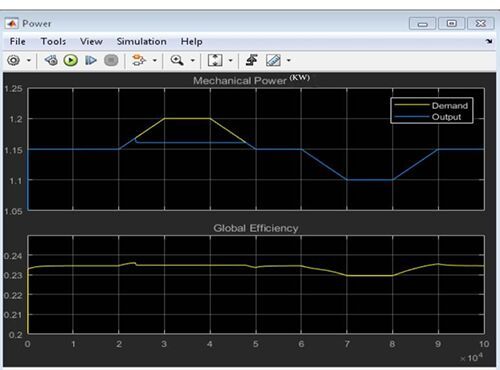
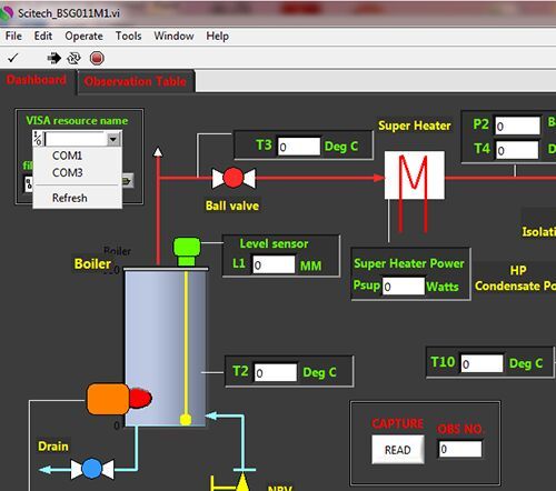
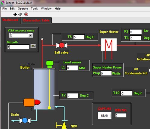


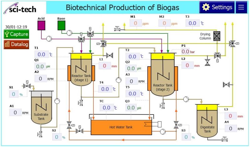
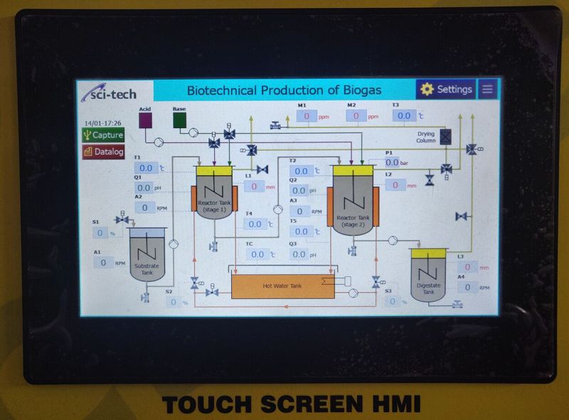
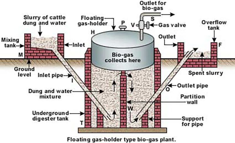
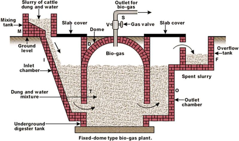
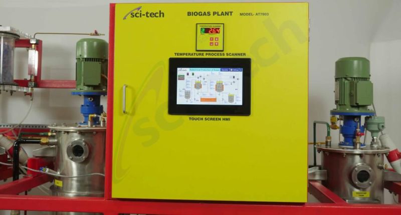

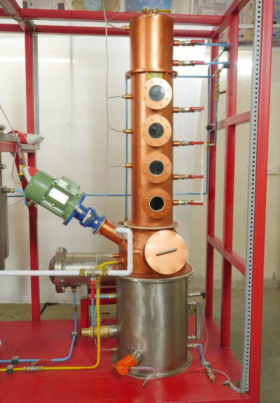
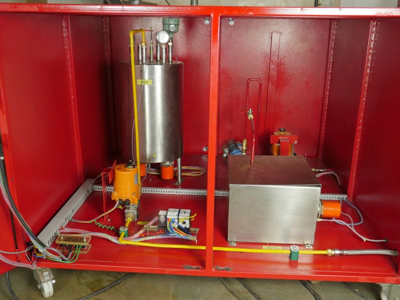
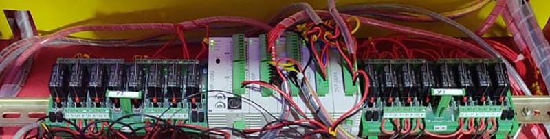
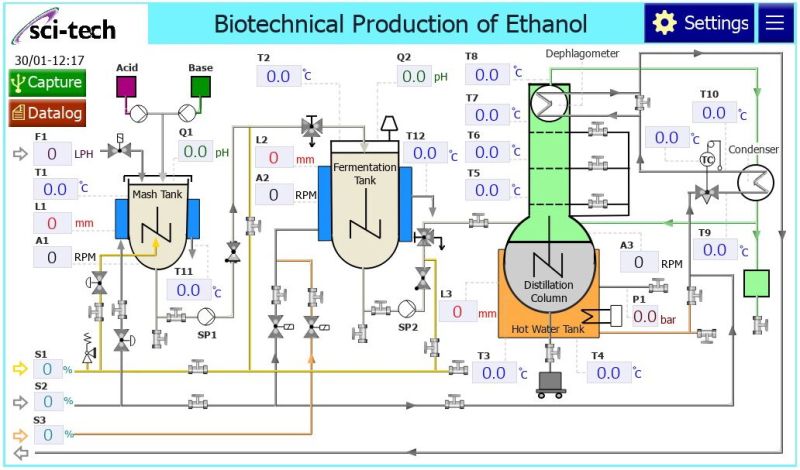
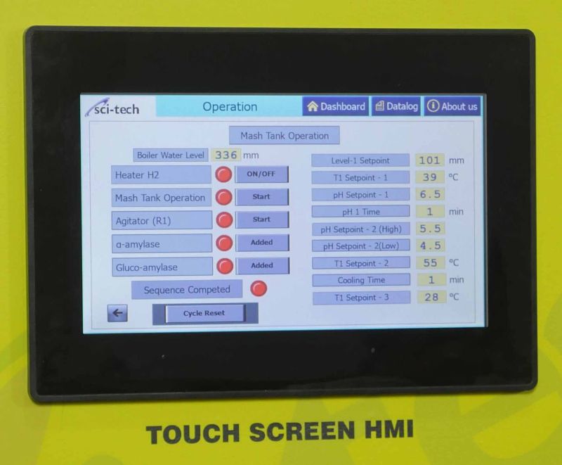

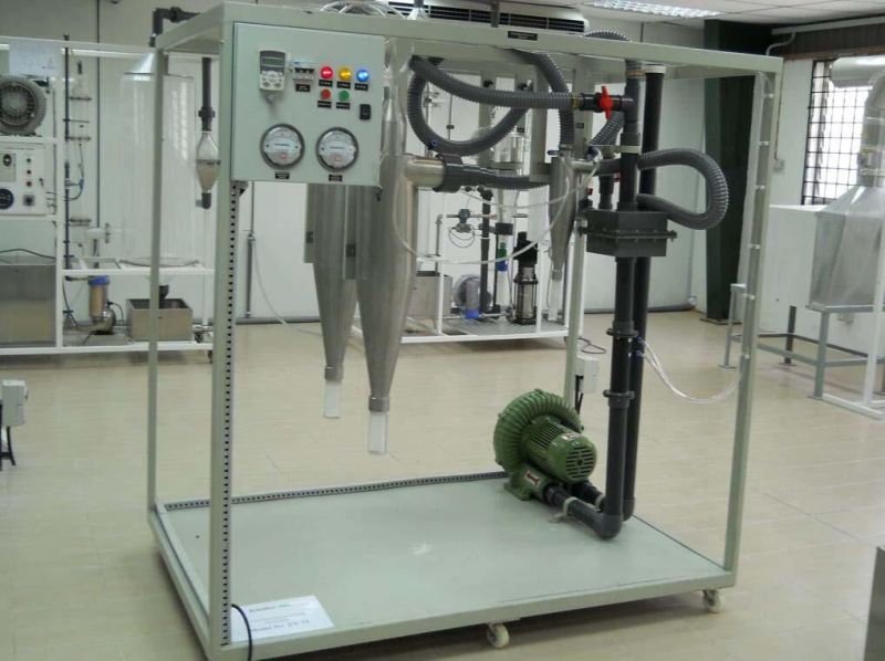

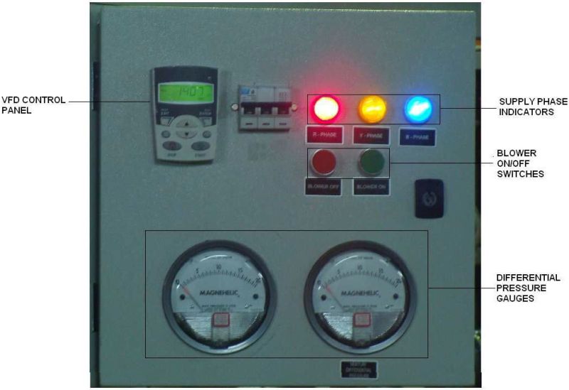
 Trainer Model Env 003")